|
|

Table Of Contents
Common Interface Module Installation
Mounting an MGX 8240 with Common Interface Module
10Base-T Cable (for Internal Management)
10Base-T Ethernet Cable (for External Management)
FDOS: Configuring the Common Interface Module
Accessing Command Line Interface on Individual Modules
Network Management and Telnet Access
Common Interface Module Installation
The Common Interface Module (CIM) is a small unit mounted above or below some MGX 8240 chassis. The CIM serves as the gateway into the MGX 8240 system. It supports Network Address Translation (NAT) in translating multiple IP addresses assigned to individual PSM cards to a single IP address to the router. It also allows multiple entries and translations for each internal IP Address.
This chapter covers the following elements of installing a CIM:
•
Site Preparation and Planning
•
•
•
•
•
•
•
Site Preparation and Planning
Install the CIM in a clean, dry, well-ventilated area. Verify that a -48 VDC source is close to where the Common Interface Module will be mounted. Also make sure that an accessible site ground is available to connect to the equipment rack.
Space Planning
The physical dimensions of the Common Interface Module are shown in Table E-1.
Table E-1 Physical Dimensions
Height
1.75 inches
Width
24.75 inches
Depth
Less than 24.5 inches
Weight
15 pounds
Cooling
Convection
Environmental Requirements
Do not place the unit in direct sunlight or where it could be subject to vibration. The unit must reside in 20% to 80% humidity, noncondensing, and in 0oC to 40oC (32oF to 113oF).
ESD/EMI Precautions
The Common Interface Module supports chassis ground (protective earth ground) for optimum performance as well as personal safety. All accessible surfaces that may become energized under a fault condition are connected to the ground.
Chassis ground points must be connected to the appropriate building ground points according to local wiring practices. Ground wires require a minimum diameter of 1.85 mm or 6 AWG (American Wire Gauge). If local codes allow grounding to the equipment rack only, ground wires are not required; use ground straps.
Caution
The Common Interface Module has been tested against all relevant standards of EMI. However, Cisco recommends that users avoid placing the rack close to very strong EMI sources such as elevators, air-conditioners, photocopiers, and fax machines.
Safety Requirements
Warning
Required Tools and Equipment
Warning
To install the Common Interface Module, you need the following:
•
•
•
Unpacking and Checking
Unpack the box(es) and check contents against the Common Interface Module shipping list (see Appendix B). Save the packaging. If the box has been damaged or if some parts are missing or defective, call Cisco and the package carrier to report the damage. Obtain a Returned Material Authorization (RMA) number from Cisco and include the RMA number with the return shipment. Return the unit in its original packaging to Cisco.
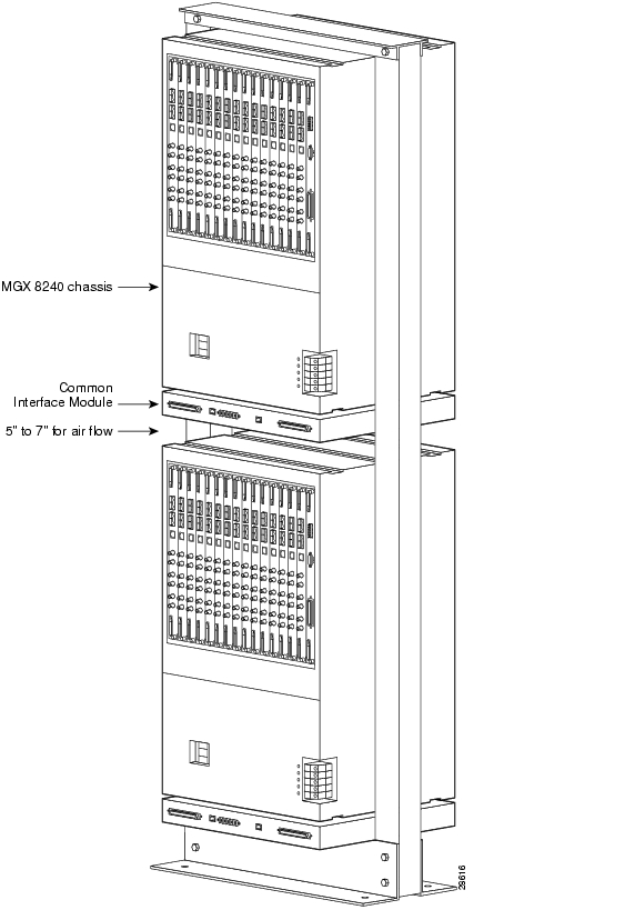
Mounting an MGX 8240 with Common Interface Module
Perform the following step to mount the Common Interface Module with an MGX 8240:
Note
•
•
Figure E-1 MGX 8240 Rack Layout (Front View)
Cabling
The following cables are required:
•
•
•
RS232 Serial Cable
Perform the following steps to attach the RS232 serial cable:
Step 1
Step 2
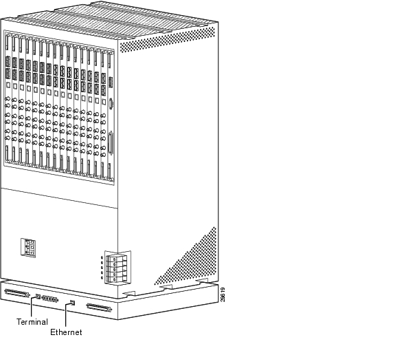
Figure E-2 RS232 Cable from Common Interface Module to MGX 8240
10Base-T Cable (for Internal Management)
Perform the following steps to attach the 10Base-T cable:
Step 1
Step 2
Figure E-3 Ethernet Common Interface Module to MGX 8240
10Base-T Ethernet Cable (for External Management)
Perform the following steps to attach the 10Base-T Ethernet cable:
Step 1
Step 2
Figure E-4 External Ethernet to Common Interface Module and Craft Connection via Common Interface Module
Making Power Connections
The Common Interface Module requires -36VDC to -56VDC power at approximately 3 Amps for a fully loaded shelf.
Note
Perform the following steps to connect power:
Step 1
Step 2
Connecting a VT-100 Terminal
Perform the following steps to connect a VT-100 terminal:
Step 1
Step 2
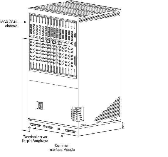
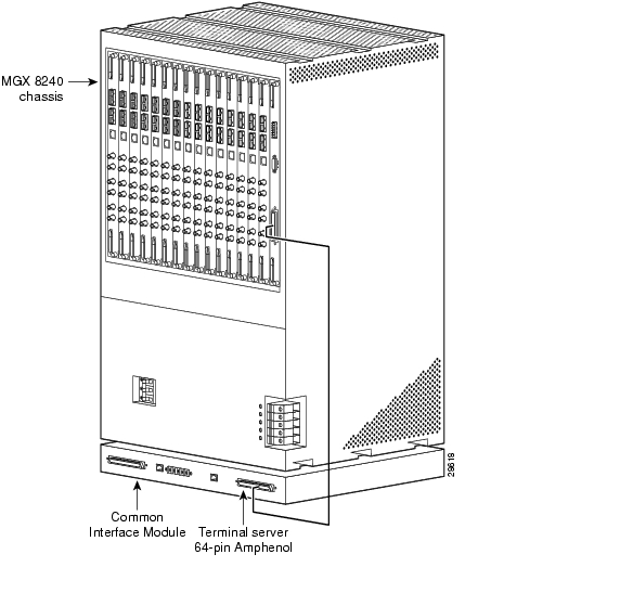
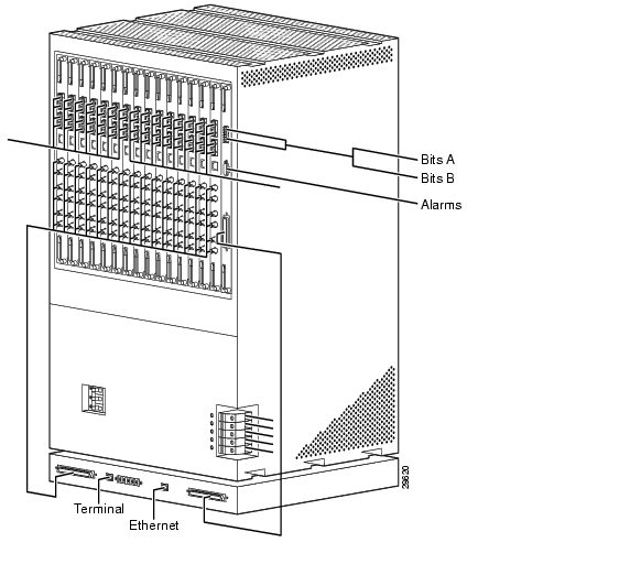
Figure E-5 Fully Cabled MGX 8240 Chassis with Common Interface Module (Rear View)
FDOS: Configuring the Common Interface Module
The Common Interface Module serial interface configuration is preset at the factory. The settings are—9600bps, no parity, 8-bit data, and 1 stop bit.
Follow the steps below to perform FDOS on the CIM.
Before you start, you will need the following information:
•
•
•
•
•
•
Make sure that you have the following five files on the floppy disk:
•
•
•
•
•
Step 1
Step 2
Step 3
Option Format
The option format is as follows:
•
•
•
•
•
•
•
Note
Once all data has been entered, three configuration scripts are generated. The configuration application automatically applies these scripts to terminal server A, terminal server B, and the router, respectively. This process takes approximately ten minutes.
During the configuration process, each line displays as it is applied. When the process ends, a summary of the results of each script is printed. The summary indicates whether or not parameters were set on each of the three devices. If parameters were not set on a particular device, an Error condition exists.
Accessing Command Line Interface on Individual Modules
Modules 2 through 16 of the MGX 8240 have a command line interface (CLI) and can be accessed two ways: directly through a serial port or via telnet through the IP network. To access a CLI through a serial port, perform the following steps:
Step 1
Step 2
Step 3
Step 4
connect p<slotid>-<chassisID>
For example, if you were logging in to slot 14 on chassis 10, you would enter connect p14-10.
Step 5
You are now communicating with the CLI of that module.
Note
Logical Connections
The Common Interface Module connects to the MGX 8240 chassis by two forms, a 10Base-T Ethernet and one RS232. Single IP address connectivity is managed through Network Address Translation (NAT) so that MGX 8240 appears as a single IP address.
Network Management and Telnet Access
Telnet, FTP, and Network Management traffic are accomplished by communication to a single address, which is managed by the Common Interface Module.
Single Address Translation
Address translation is handled by NAT software residing on the Common Interface Module. NAT software allows Cisco to present a single IP address while translating independent slot addresses as required for network service and troubleshooting.
![]()
![]()
![]()
![]()
![]()
![]()
![]()
![]()
Posted: Wed Aug 25 16:55:00 PDT 2004
All contents are Copyright © 1992--2004 Cisco Systems, Inc. All rights reserved.
Important Notices and Privacy Statement.