cc/td/doc/product/wanbu/mgx8240/rel22
hometocprevnextglossaryfeedbacksearchhelp
PDF

Table Of Contents

Retrofit MGX 8240 Installation Addendum

Mounting an MGX 8240

Installing Circuit Breaker Cover

Retrofitting the DC Power Entry

Making Power Connections

Retrofit MGX 8240 Installation Addendum


Persons who receive the MGX 8240 Retrofit Shipping Kit should use this information.

You will need the following tools for this installation:

1/2" deep socket with ratchet, or 1/2" open-ended wrench

1/4" nut driver or 1/4" socket with ratchet

7/16" nut driver, or 7/16th socket with ratchet

#1 Phillips screwdriver

#2 Phillips screwdriver


Note Make sure power is turned off.


Mounting an MGX 8240

Before attempting to handle electronic parts, put on a grounded antistatic wrist strap. Perform the following steps:


Step 1 Use the bolt-positioning template provided by Cisco to plan position of bolts. You may find it helpful to install some bolts from the back to the front before lifting the chassis into place. (If you do install bolts from the back, you will need to put nuts onto the bolts once the chassis is in place.)

Step 2 Position the MGX 8240 at the top of the equipment rack or otherwise as planned by engineers. Cisco recommends that installers have four people lift the chassis into place. If four people are not available, use a hand lift.

Step 3 Screw in bolts or nuts.


Note A maximum of two MGX 8240s can be mounted in a 7-foot rack.


Installing Circuit Breaker Cover

Retrofitting the Circuit Breaker Cover involves installing a Metal cover over the existing circuit breaker. This modification uses the parts described in Table C-1

Table C-1 Circuit Breaker Retrofit Parts

Item
Quantity
Part Number
Description

23

1

075A040800

Cover, circuit breaker

24

4

1209600980

Standoff

26

8

1209600931

Tooth lock washer #6 (from existing circuit breaker)

9

4

1209600938

Phillips pan head screw (from existing circuit breaker)

10

4

1209600942

Flat washer #6 (from existing circuit breaker)


Figure C-1 Breaker with Standoff (Top View)

Perform the following steps:


Caution For safety, disconnect -48 VDC from the MGX 8240 chassis.

Step 1 Using the #1 Phillips screwdriver, remove the four existing corner screws and eight washers from the existing circuit breaker. Retain four screws (item 9 in Figure C-1) and all eight washers (items 10 and 26 in Figure C-1).

Step 2 Replace all washers on bases of all four standoffs (item 24 in Figure C-1; P/N 1209600980). The flat washer should be innermost, closest to the switch. Thread standoffs (with washers at bases) into holes. Tighten to approximately 10 foot-pounds of torque.

Step 3 Hold circuit cover (Item 23 in Figure C-1, P/N 075A040800) in place, with the painted side out. Screw in the four flathead screws (Item 9 on Figure C-1, from existing switch) with lock washers.


Retrofitting the DC Power Entry

The DC Power Entry Change involves adding a terminal block to allow the use of a two hole terminal lug. The block consists of the parts listed in Table C-2.

Table C-2

Item
Qty
Part Number
Description

18

1

140A041100

Insulator, Buss Bars U1600

19

5

021A041200

Buss Bar, Power Input U1600

22

10

1209600988

Screw, 1/4 - 20 X 3/8 Hex

11

1

075A040900

Cover, Power Stud Safety U1600

33

2

1209600930

Screw, FH 6-32 x 1/2

25

15

1209600989

1/4 Ext Tooth Lock Washer


DC Power Entry Parts

Figure C-2 Power Connector Block (Exploded View)

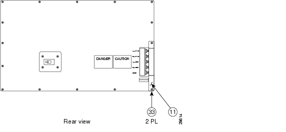
Figure C-3 Chassis Power Input (Rear View)

Perform the following steps to install the Buss Bars:

At the rear of the MGX 8240, the DC Power Input consists of five 1/4" studs.


Step 1 Remove all five 7/16" nuts and all washers.

Step 2 Install the Buss Bar Insulator (P/N 140A041100), with the flat side towards the center of the switch.


Note As you place the Buss Bar Insulators, in Step 3, be sure that the cut-out faces into the switch.


Step 3 Install each of the Power Input Buss Bars. Each Buss Bar is held in place by using a lock washer and 7/16" nut. Tighten the nut and make sure that the Buss Bar is aligned with the Insulator so that there is no binding.

Step 4 You will position the outer safety cover after making power connections to the rear panel (using two #6-32 1/2" flat head screws).


Making Power Connections


Note The MGX 8240 requires -38 VDC to -54 VDC power at approximately 40 Amps for a fully loaded shelf.


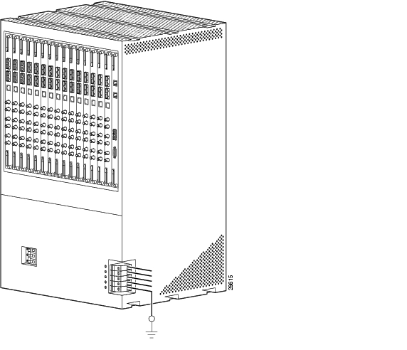
Perform the following steps to connect DC power to the MGX 8240:


Step 1 Reconnect the -48VDC. (Cisco recommends number #6 AWG Solid Wire). The MGX 8240 supports dual DC feeds. Determine if you want two separate feeds or just one.

Step 2 Connect one end from the DC power into the MGX 8240 connector block as shown in the figure below. Use a 1/4" lock washer between each screw and terminal lug.

Step 3 After connecting the power, returns and ground, install the safety cover. The safety cover is held in place with two #6-32 1/2" flat head screws.


Figure C-4 MGX 8240 with DS3 on Rack (Rear View)

Table C-3 Cabling for MGX 8240 on Rack

Cable Type
Connector Type
Purpose

Power

#6 AWG; lug

Supplies -48 V DC power to MGX 8240


The retrofit installation is now complete.


hometocprevnextglossaryfeedbacksearchhelp

Posted: Wed Aug 25 16:54:30 PDT 2004
All contents are Copyright © 1992--2004 Cisco Systems, Inc. All rights reserved.
Important Notices and Privacy Statement.