|
|

Table Of Contents
Cabling for RJ-48 Connectors on T1 and E1 Ports
Cabling Summary
Introduction
This appendix provides details on the cabling required to install the MGX 8220 shelf.
Note
In all cable references, the transmit direction is from the MGX 8220 shelf, receive is to the MGX 8220 shelf.
T3 Trunk Cabling
Trunk cables connect the T3 port on the BNM backcard to the BNI T3 port on the colocated BPX node. See Table A-1 and Table A-2 for details.
Table A-2 T3 Connector Pin Assignments
Rx BNC
Receive T3 from trunk
Tx BNC
Transmit T3 to trunk
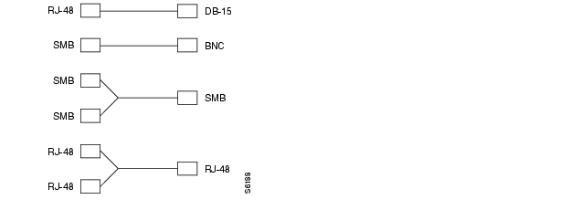
IMATM T1/E1 Connectors
The IMATM backcard can have eight RJ-48 connectors or eight SMB connectors. Connections are made through short pigtail cables, two adapter cables, and two Y-cables for use with redundant IMATM cards. (See Figure A-1.)
Figure A-1 IMATM T1/E1 Pigtail Cables
Frame Relay Cabling
T1 Cabling
Trunk cables connect the customer DSX-1 crossconnect point or T1/E1 channel service unit to the MGX 8220 node at the FRSM T1 back card (DB15-4T1). See Table A-3 and Table A-4 for details.
Table A-4 T1 Connector Pin Assignments
1
Transmit, tip
2
Transmit, pair shield
3
Receive, tip
4
Receive, pair shield
9
Transmit, ring
11
Receive, ring
Note
E1 Cabling
BNC Connector
E1 trunk cables connect the customer DSX-1 crossconnect point or E1 channel service unit to the MGX 8220 node at the FRSM E1 back card (BNC-4E1). (See Table A-5 and Table A-6.)
Table A-6 E1 Connector Pin Assignments (unbalanced)
Rx BNC
Receive E1 from trunk
Tx BNC
Transmit E1 to trunk
DB-15 Connector
E1 trunk cables connect the customer DSX-1 crossconnect point or E1 channel service unit to the MGX 8220 node at the FRSM E1 back card (DB15-4E1). (See Table A-7 and Table A-8.)
Table A-8 E1 Connector Pin Assignments
1
Transmit, tip
2
Transmit, pair shield
3
Receive, tip
4
Receive, pair shield
9
Transmit, ring
11
Receive, ring
Note
X.21 Port Connectors
The X.21 ports use DB-15 female connectors (DCE type according to ISO 4903.) (See Table A-9.)
HSSI Port Connectors
The HSSI (High-Speed Serial Interface) port uses a female SCSI-II connector (connector type according to ANSI/TIA/EIA-613). (See Table A-10.)
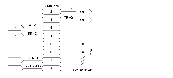
Cabling for RJ-48 Connectors on T1 and E1 Ports
For back cards using RJ-48 connectors on T1 and E1 ports, each connector has
•
•
•
•
•
The pins are wired as shown in Figure A-2.
Figure A-2 RJ-48 Connectors
DC Power Cabling
DC power connections are made to the DC power entry modules at the rear of the MGX 8220 shelf. (See Figure A-3.) See Table A-11 and Table A-12 for acceptable cable and wire types.
DC wiring is generally provided by the customer. (See Table A-11.)
Figure A-3 DC Power Connections
AC Power Cabling
AC power cables can be provided by the customer or ordered from Cisco. Several standard cables are available. (See Table A-12.) AC cables with other plugs or different lengths can be special ordered. For users who wish to construct their own power cables, the cable must mate with an IEC320 16/20A male receptacle on the rear of the AC power module.
Control and Clock Cabling
Maintenance and Control Ports
The control ports are used to connect one of the nodes in the network to a control terminal, workstation, or modem connections for remote alarm reporting or system monitoring. Refer to Table A-13 and
Table A-14 for details on these cables.
Table A-13 Maintenance and Control Port Cabling
Interface
RS-232 DCE ports.
Suggested cable
24 AWG, 25-wire. A straight-through RS-232 cable is used for a terminal or printer connection. A null modem cable is needed when interfacing with modems on either port.
Cable connector
DB-25, subminiature, male. Table A-14 contains a list of the port pin assignments.
Max. cable length
50 feet (15 m)
Table A-14 Maintenance and Control Port Pin Assignments
1
FG
Both
Frame ground
2
TxD
DTE
Transmit data
3
RxD
DCE
Receive data
4
RTS
DTE
Request to send
5
CTS
DCE
Clear to send
6
DSR
DCE
Data set ready
7
SG
Both
Signal ground
8
CD
DCE
Carrier detect
181
LL
DTE
Local loop
20
DTR
DTE
Data term ready
211
RL
DTE
Remote loop
221
RI
DCE
Ring indicator
1 Used on control port cable only.
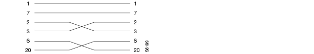
Modem Cable
Figure A-4 shows a modem cable that is used for connecting modems to the MGX 8220 control and maintenance ports.
Figure A-4 Null Modem Cable
External Clock Input Cabling
The external clock input cable connects the external clock inputs through the T3/E3-D, T3/E3-B, and SMF-155 EXT. TMG. connectors. The clock is 1.544 Mbps for T3/E3-D or 2.048 Mbps for T3/E3-D. (See Table A-15 through Table A-18.)
T1/E1 Clock Cabling
The DB-15 clock port can be used for accepting a T1 or E1 BITS clock input.
Table A-15 External Clock Cabling—T3/E3-D or SMF-155
Cable type
Western Electric 22 AWG, ABAM individually shielded twisted pair (100 ohm balanced). One pair per T1 line (one receive).
Cable connector
Male DB-15 subminiature. Refer to Table A-16 for pinouts.
Max. cable length
533 ft (162 m) max. between the MGX 8220 shelf and the first repeater or CSU. Selection of cable length equalizers is used. Wire buildout is required.
.
Table A-16 T1 Connector Pin Assignments for EXT. TMG
1
2
Transmit, pair shield
3
Receive, Tip
4
Receive, pair shield
9
11
Receive, Ring
E1 Clock Cabling
T3E-B, T3/E3-D, or SMF-155
Table A-18 E1 Connector Pin Assignments for EXT.TMG (unbalanced)
Rx BNC
Receive E1 from trunk
External Alarm Cabling
This cable (see Table A-19) connects network alarm outputs to the LM-BNM alarm output connector only. Table A-20 lists the pinouts for the network alarm outputs.
Table A-19 External Alarm Cabling
Interface
Dry-contact relay closure
Wire
24 AWG, shielded, 6-pair
Connector
DB-15, subminiature, male
Standard MGX 8220 Cables
Table A-21 lists the various cables that can be ordered directly from Cisco. Cable lengths are specified as a suffix to the model number. For example 5610-50 indicates a 50-foot cable. Cables are generally available in standard lengths of 10 feet (3 m), 25 feet (7.6 m), 50 feet (15 m), 75 feet (22.8 m) and 100 feet (30 m). Lengths of 101 feet (30 m) to 600 feet (183 m) are available on a special order.
When a cable is connectorized, the connector gender (male-female) will be indicated as well as the number of pins. For example, RS-232/M25-M25 indicates a cable terminated with a male DB-25 at both ends.
Redundancy Y-Cables
The redundancy cables are special Y-cables available from Cisco. These cables are required for redundant trunk and data interfaces. Table A-22 lists the Y-cables used with various MGX 8220 back cards.
![]()
![]()
![]()
![]()
![]()
![]()
![]()
![]()
Posted: Wed Nov 10 21:49:23 PST 2004
All contents are Copyright © 1992--2004 Cisco Systems, Inc. All rights reserved.
Important Notices and Privacy Statement.