|
|

Table Of Contents
Introduction
This manual describes how to install, troubleshoot, and repair a Cisco IGX 8400 series node running Release 9.3 of the system software. In addition to the chapters that provide these descriptions, the appendices in this manual describe system specifications for the operating environment and data transport technologies, supported peripherals, cabling, and the possible arrangements for all series of Cisco WAN switches in a Cisco rack.
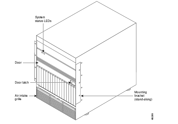
The Cisco IGX 8400 series of WAN switches consist of the IGX 8410, IGX 8420, and IGX 8430. A Cisco IGX 8400 series switch can reside in a rack or a stand-alone cabinet. illustrates an IGX 8410 mounted in a cabinet.
For descriptions of the hardware in an IGX 8410, IGX 8420, or IGX 8430 node, refer to the
Cisco IGX 8400 Series Reference.This manual also contains Appendix E, "Service Expansion Shelf Feeder" which describes configuring a Cisco Service Expansion Shelf (SES) as an IGX feeder. This appendix is meant to be used in conjunction with the Cisco Service Expansion Shelf Hardware Installation Guide.
The installation and related topics in this manual consist of the following:
1
Enclosure or rack installation
This includes procedures for installing all switches in the IGX series in a cabinet or rack, using appropriate tools and mounting rails.
2
Mounting procedures for the AC or DC power supplies, installation of redundant power supplies and procedures for connection to the power-entry vback cards.
3
Installation of cooling fans in the IGX enclosure.
4
Connecting the IGX to power and ground.
5
Procedures for installing the various front and back cards available for the IGX node.
6
Starting the node for the first time.
7
General directions for isolating a problem area and possible quick fixes.
8
9
10
The remaining pages of this chapter illustrate the models in the IGX series.
Figure 1-1 IGX 8410 Node
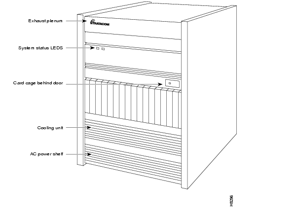
illustrates an IGX 8420 switch in a stand-alone cabinet.
Figure 1-2 IGX 8420 Node
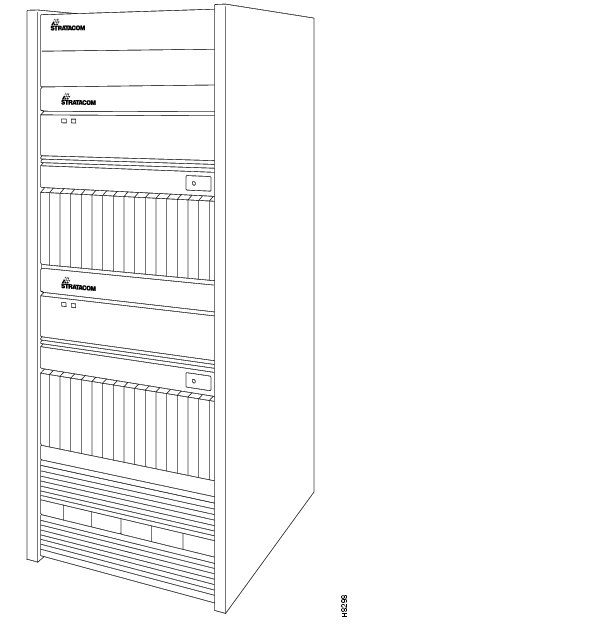
illustrates the IGX 8430 in a Cisco-supplied cabinet.
Figure 1-3 IGX 8430 Node
For descriptions of the hardware in an IGX 8410, IGX 8420, or IGX 8430 node, refer to the
Cisco IGX 8400 Series Reference.An IGX series switch is installed in the following steps:
1
This includes procedures for installing all switches in the IGX series in a cabinet or rack, using appropriate tools and mounting rails.
2
Mounting procedures for the AC or DC power supplies, installation of redundant power supplies and procedures for connection to the power-entry vback cards.
3
Installation of cooling fans in the IGX enclosure.
4
Connecting the IGX to power and ground.
5
Procedures for installing the various front and back cards available for the IGX node.
6
Starting the node for the first time.
![]()
![]()
![]()
![]()
![]()
![]()
![]()
![]()
Posted: Wed Nov 10 23:36:58 PST 2004
All contents are Copyright © 1992--2004 Cisco Systems, Inc. All rights reserved.
Important Notices and Privacy Statement.