|
|

Table Of Contents
Processor, Trunk, and Alarm Card Types
Optional Alarm Interface Cards
Maintenance and Troubleshooting
Common Alarms, Controls, and Indicators
Introduction to the UXM Trunk Mode
E1 Interface Back Card (BC-E1)
Subrate Interface Card (BC-SR)
Y1 Interface Back Card (BC-Y1)
Descriptions of BTM Back Cards
Interface Back Cards for the ALM/B
Processor and Trunk Cards
This chapter describes the hardware and functionality of the processor and trunk cards. It also describes the backplane and system bus. The description of each card includes:
•
Function
•
•
Other manuals that relate to IGX operation are:
•
•
•
Processor, Trunk, and Alarm Card Types
lists the processor cards that can operate in an IGX switch. lists the trunk front cards, and lists the corresponding trunk interface back cards. The card described in this chapter that is neither a processor card nor a trunk card is the Alarm Relay Module card set (ARM/ARI). In addition, a switch may use Adapter Card Modules (ACMs) to connect existing IPX 16/32 service modules and perform the adaptation that allows IPX 16/32 front cards to operate in an IGX 8410, 8420, or 8430. IPX 8-specific cards do not apply to the upgrade scheme.
Table 3-1 Processor Cards
NPM-32
Nodal Processor Module with 32 Mbytes DRAM
NPM-64
Nodal Processor Module with 64 Mbytes DRAM
NPM-64B
Nodal Processor Module with 64 Mbytes DRAM
Table 3-2 Trunk Front Cards
UXM
Universal Switching Module
ALM/B
ATM Line Module, Model B
BTM
Broadband Trunk Module
NTM
Network Trunk Module
Table 3-3 Interface Back Cards for Trunks
Table 3-4 Other Back Cards
SCM
System Clock Module, works in conjunction with the NPM
ARI
Alarm Relay Interface, works in conjunction with the ARM card
Processor Cards
The processor card group consists of the Nodal Processor Module (NPM) and the System Clock Module (SCM). In conjunction with the system bus, the processor group is responsible for system timing, network control, and status reporting.
Nodal Processor Module (NPM)
The Nodal Processor Module (NPM) is a 68040 microprocessor-based system controller that runs the software for controlling the IGX switch. The NPM communicates with the other system cards over the control bus. illustrates the relation of the NPM to other parts of the system. The NPM performs the following major functions:
•
•
•
•
•
The NPM communicates with all other nodes through a trunk that uses a reserved queue on the trunk. The NPM communication link with other nodes carries information about new connections, topology changes, and rerouting.
One version of the NPM-32 and two versions of the NPM-64 are supported. The three NPMs are as follows: NPM-32, NPM-64, and NPM-64B. In addition, the NPM-32 and NPM-64B use +5 VDC flash memory. NPM-64 and NPM-64B can be used in the same node. The next section, titled " NPM Processor and Memory Capacity," describes NPM memory.
Figure 3-1 NPM in Relation to the System
NPM Processor and Memory Capacity
The DRAM memory in an NPM holds the switch software for performing the regular functions of the NPM. The NPMs also have memory features that let you download new software releases over the network and maintain the system software and its configuration if the power fails. Non-volatile flash EEPROM supports software downloading over the network. Battery-backup RAM (BRAM) stores system configuration data. shows the memory capacity of each NPM.
Table 3-5 NPM Memory
NPM-32
32 Mbytes
1 Mbyte
4 Mbytes
NPM-64
64 Mbytes
1 Mbyte
4 Mbytes
NPM-64-B
64 Mbytes
4 Mbytes
4 Mbytes
NPM Redundancy
An IGX has one NPM in a non-redundant system or two NPMs in a redundant system. In a non-redundant system, an NPM resides in either front slot 1 or front slot 2. For a redundant system, NPMs reside in slots 1 and 2. The NPM plugs into the system bus backplane. A utility bus in the backplane connects the NPMs in a redundant system.
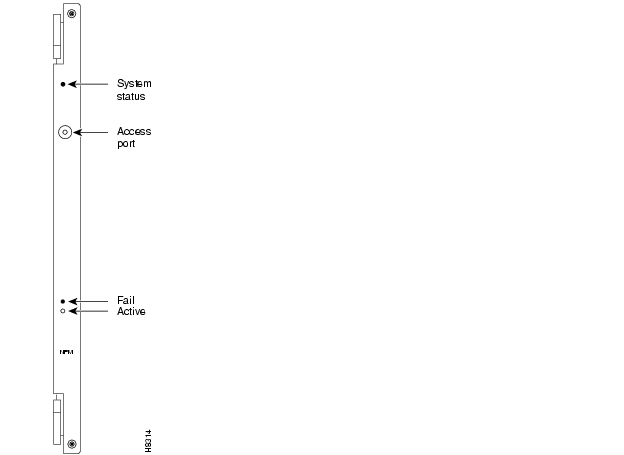
NPM Faceplate and LEDs
The faceplate of the NPM has a green Active LED and a red Fail LED. See . The NPM monitors its own activity and, if a failure is detected, the Fail LED is lit. If the node has redundant NPMs, the on-line NPM is indicated by the lit Active LED, while the standby NPM has no lit indicators. In addition to the status LEDs on the NPM faceplate, information on any NPM can be displayed at a terminal by executing the dspcd command.
Figure 3-2 NPM Faceplate
System Clock Module (SCM)
The System Clock Module (SCM) card provides the main clock generation function for the IGX. It generates the system clock and trunk synchronizing clocks. The SCM phase-locks the internal IGX timing to the selected clock source for network synchronization. Each IGX node must have an SCM. The SCM plugs into back card slot 1.
SCM Features and Functions
The NPM and SCM card sets are the backbone of the IGX: without an NPM and SCM, the node is inoperative. The NPM controls and monitors the SCM control buses. A single SCM can support redundant NPMs.
In addition, the SCM provides:
•
•
The SCM circuits include the following:
•
•
•
•
•
•
•
•
•
The two serial EIA/TIA-232 ports provide connection to control terminals and modems for remote access to the node. In conjunction with the SCM, the NPM also supports a high-speed Ethernet LAN port for faster system statistics transfer between the node and a StrataView Plus NMS workstation. This port conforms to the requirements of IEEE standard 802.3 for Ethernet.
The SCM has duplicates of the internal clock circuitry and its associated phase lock loops and NPM-related control circuitry. One clock circuit operates off the System A Bus, and the other operates off the System B Bus. Both circuits operate independently and are monitored separately to provide complete backup if a circuit fails (which would cause the Fail LED to turn on). However, because both the System A bus and System B bus clock circuits exist on a single card, removing the SCM disrupts system operation. The lower priority SCM circuits are not duplicated. The lower priority circuits are the external clock input, control and auxiliary ports, and monitoring circuits for power supplies, cabinet temperature, and fans. A failure in a lower priority circuit does not cause a system failure, but the SCM reports the problem.
The Ext Clock connector on the faceplate of the SCM provides an interface for an external source for a high-stability clock. This clock is configurable as the primary, secondary, or tertiary clock. The input is 1.544 MHz for T1 systems and 2.048 MHz for E1 systems. In addition, one of the trunk or circuit line inputs may also serve as a source of timing for the node. If no clock source is selected, the clock source is the internal IGX clock.
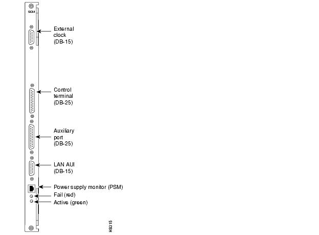
and describe the SCM faceplate connectors and LEDs. When you correlate the descriptions in the table with the callouts in the figure, read from the top to the bottom.
In addition to the clock functions, the SCM provides a pair of low-speed, serial communications ports. The control terminal port is a bi-directional port for connecting the IGX to a local network control terminal or to a modem for remote terminal connection. The auxiliary port connects to a maintenance log printer, an additional dumb terminal, an alarm message collector, external device window, or an auto-dial modem for automatic reporting of local IGX alarm conditions. You can program the modem to dial into the Technical Assistance Center (TAC) for assistance when a network alarm occurs. You can reach the TAC through Cisco Customer Engineering at 800-553-2447 or 1-408-526-4000.
Figure 3-3 SCM Faceplate
Table 3-6 SCM Faceplate Connectors and Indicators
External Clock
DB15 connector for connecting an external source for the system clock.
Control Terminal
A DB25 connector for a VT100 or equivalent terminal for a basic network management terminal. control terminal can also connect to a dial-in modem for communication with the TAC or other network management dial-up access. This is a bidirectional EIA/TIA-232 communications port.
Auxiliary Port
A DB25 connector for a system printer. Can also be used to connect an out-dial modem for automatic reporting of alarms if the node becomes isolated. This port is bidirectional EIA/TIA-232.
LAN AUI
Ethernet LAN connection for multiple, local StrataView Plus NMSs. This port uses a DB-15 connector called the Attachment Unit Interface (AUI) connector. This name reflects the industry standard term for a LAN interface. lists the AUI pin assignments.
Power Supply Monitor (PSM)
Power supply monitor. You must supply the cable to use the PSM connector. See the section titled " Using the Power Supply Monitor Connector."
Fail
Indicates an error occurred. First, reset the card with the resetcd f command. If the LED comes on again, call the TAC.
Active
Indicates the card is in service with active circuits.
lists the pin assignments for the LAN connector.
Table 3-7 AUI Connector Pin Assignments (DB 15-connector)
Using the Power Supply Monitor Connector
The Power Supply Monitor (PSM) is an RJ-45 connector with the following pinout:.
•
•
•
Each AC power supply provides an open collector output that goes low if an AC power failure occurs. The inactive state of the status signals is high on the SCM. The signals go into a ALS244 driver, the outputs of which are connected directly to the RJ-45 connector as well as circuitry that communicates the status to the control card. To use the PSM connector, you need a device that responds with a fail condition when a "0" TTL logic level is present on pin 2 or pin 3.
Optional Alarm Interface Cards
The alarm relay card set is optional. The set consists of an Alarm Relay Module (ARM) front card and an Alarm Relay Interface (ARI) back card. This card set provides alarm summary outputs by using relay contact closures.
The alarm outputs are typically wired to a telephone central office alarm system for remote alarm reporting to give an indication there is a problem in the associated equipment.
The alarm summary feature provided by the Alarm Relay cards provides both a faceplate visual indication of an IGX node alarm as well as a set of relay outputs (dry-contact) for indicating node and network alarm indications. A visual alarm history indication is also provided. This alarm reporting is separate and is in addition to the alarm output at the node's control port, which provides a data output to a control terminal, such as the StrataView Plus Network Management Station. summarizes the alarm conditions and the resulting indications.
One set of alarm relays is used to signal a major alarm or minor alarm on the node. One pair of contacts on each relay is used for audible alarms. These contacts are in series with a faceplate alarm cut-off (ACO) switch. The other set of relay contacts are used for visual alarms and are not affected by the ACO switch. When the ACO switch is activated, a faceplate ACO indicator lights up as a reminder to the operator. If the ACO switch is activated to disable the node's audible alarm output and a second alarm occurs, the audible alarm is re-activated. Two faceplate LEDs provide local indication of network alarms.
Table 3-8 ARM Card Set Alarm Reporting
A second, independent, set of alarm outputs report network alarms. If a major or minor alarm occurs anywhere in the network, the ARM activates these relays.
Major alarm relays are normally energized, providing an open circuit, so that a complete power failure (relay de-energized) at the node results in a contact closure and resulting major alarm output. Minor alarms, however, are normally de-energized to conserve power. Contact closures as well as contact openings are available for minor alarms.
When an alarm condition clears, the alarm relays return to their normal state to clear the alarm outputs. A faceplate history indicator turns on when a local alarm occurs. The indicator remains on even though an alarm may have already cleared. You can manually clear the history indicator by pressing a switch on the faceplate.
Two additional relays exist under software control to report conditions but are currently unassigned.
The alarm reporting feature requires a card set that includes an ARM front card and an ARI back card. This card set can reside in any slot except the reserved slots. However, Cisco recommends that the front card go in the slot on the far right. Since a failure of either of these cards does not affect service, card redundancy is not necessary.
Alarm Relay Module (ARM)
The alarm relays are controlled by system software through Control Bus commands. The ARM interface with the Control Bus allows the card to receive alarm signals from the NPM and to send status signals back to the NPM. The firmware on the ARM decodes the alarms. The ARM does not connect to the Cellbus because it does not packetize user-data.
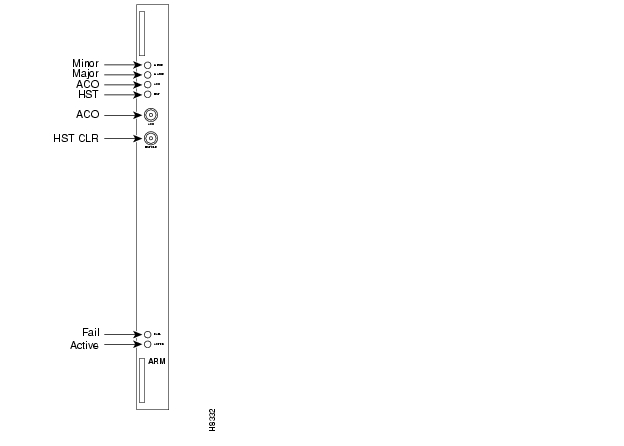
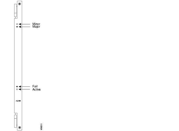
The ARM faceplate contains the alarm LEDs, ACO and History Clear push buttons, and the active and fail LEDs indicating the status of the ARM card (see and ). The ARM card is used in conjunction with an ARI card. The ARI card connects to the ARM at the P2 connector. Relay drive signals originate in the ARM to operate relays on the ARI.
The ARM periodically runs a background self-test to determine the state of the card. If the card fails this self-test, the faceplate Fail LED turns on, and the Active LED turns off.
Figure 3-4 ARM Faceplate
Table 3-9 ARM Faceplate Controls and Indicators
The installation of the ARM cards requires the removal of the node from service. The ARM can be physically installed in any front slot except slots normally reserved for the node processor cards (NPMs). For standardization, Cisco recommends that the ARM reside in the slot at the far right side of the card cage. The corresponding back slot must have an ARI card. The ARI card plugs directly in the ARM card.
User-Commands
Three commands apply to the ARM card set:
•
•
•
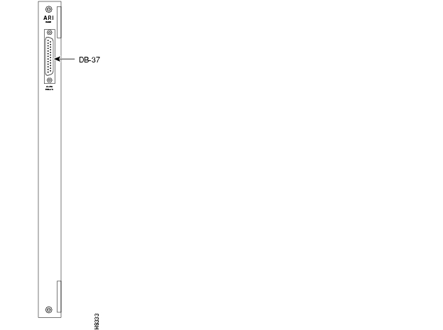
Alarm Relay Interface Description (ARI)
The Alarm Relay Interface (ARI) card contains the alarm relays and their associated relay drivers. Alarm outputs are dry contact closures or opening contacts from Form C relays. The user must supply the voltage source to be switched by the IGX. Any source or load can be switched as long as it meets the following requirements.
•
•
•
A female DB37 connector resides on the faceplate for connection to the customer's office alarm or alarm-reporting system. Refer to for an illustration of the ARI faceplate.
Figure 3-5 ARI Faceplate
Maintenance and Troubleshooting
The following paragraphs describe the maintenance and troubleshooting features associated with the ARM card set. Preventive maintenance is not necessary.
Card Self Test
Diagnostic routines periodically run to test the card's performance. These diagnostics run in the background and do not disrupt normal traffic. If a failure is detected during the self test, the faceplate red Fail LED turns on. In addition, you can check the status of the card by using the Display Card (dspcd) command at the control terminal. If a card failure is reported, the report remains until cleared. To clear a card failure, use the Reset Card (resetcd) command.
Two types of resets are exist. They are hardware and failure. The reset failure clears the event log of any failure detected by the card self test and does not disrupt card operation. The hardware reset reboots the firmware and resets the card, which momentarily disables the card.
Card Replacement
ARM card set replacement is the same as other card replacement. For these procedures, refer to the repair and replacement description in the Cisco IGX 8400 Series Installation manual.
Adapter Cards
Cisco can upgrade IPX service/interface cards for use in an IGX node. The upgrade involves the addition of one of three possible Adapter Card Modules (ACM) and possible firmware or hardware modifications. The upgrade is available only as a factory upgrade due to the complexity of the ACM.
Connecting IPX front cards to their corresponding back cards on the IPX requires the use of a utility or local bus. On upgraded IPX cards (IGX cards), the local or utility bus is not necessary.
The following IPX cards can be adapted for use in the IGX:
•
•
•
•
•
•
•
•
Trunk Interface Cards
This section describes the IGX trunks. The card groups are:
•
•
•
•
Note
Trunk Operating Modes
IGX trunk cards operate in either simple gateway or cell forwarding mode. Simple gateway supports service interworking, which lets frame relay connections terminate at ATM endpoints. For a description of simple and complex gateways, service and network interworking, tiered networks, trunks, ATM protocols, and cell and header formats, refer to the Cisco System Overview.
Trunk Card Maintenance
Trunk cards require no maintenance except for replacement after a confirmed failure.
Loopback Test
A trunk loopback test runs when an ATM trunk detects an integrated alarm. The loopback test indicates if the line or the card is faulty. A loopback test "pass" means the line is faulty, so a line alarm is subsequently indicated. A loopback test "fail" means the card is faulty. If the card is faulty, a switch occurs to an available Y-Cable equipped redundant card.
Common Alarms, Controls, and Indicators
Front cards and back cards have faceplates with indicator LEDs. Most cards have both a green Active LED and a red Fail LED at the bottom of the faceplate. For definitions of the port status LEDs on a back card, refer to the section that describes the back card.
Note
Table 3-10 Common Card Status Indicators
Universal Switching Module
This description of the Universal Switching Module (UXM) covers the following topics:
•
•
•
•
•
•
•
The Universal Switching Module (UXM) can function in one of two modes. In trunk mode, the UXM supports trunks in the network. In port mode, it as either an ATM User-to-Network Interface (UNI) or a Network-to-Network (NNI) interface. The back cards support multiple ports operating at OC3/STM1, T3, E3, T1, or E1 rates.
Note
On the other hand, a "port" is also a layer of logical functionality that applies to port cards as well as trunk cards. For example, whether you activate a line to a router or activate an ATM trunk to the network, you must subsequently configure the logical port in either case.
For a UXM, therefore, the documentation describes a logical "port" on a port-mode UXM for a UNI or NNI at the edge of a network, yet it also refers to a "port on a UXM trunk" as a layer of logic.
Introduction to the UXM Trunk Mode
The UXM can transport ATM cells to and from the Cellbus at a maximum rate of 310 Mbps in either direction. The UXM can support up to 8000 connections in trunk mode. These connections can be user connections, gateway connections, or networking connections.
Note
The UXM communicates only ATM cells to either the network or the CPE. On the Cellbus, however, the UXM communicates either ATM cells or FastPackets according to the card type. With another UXM, it communicates only in ATM cells. With other cards, the UXM communicates in FastPackets. Through its gateway functionality, the UXM translates between FastPackets and ATM cells so it can transport voice, data, or Frame Relay traffic that other cards have put in FastPackets.
Determining the UXM's Mode of Operation
The UXM detects reports its mode of operation to switch software when you first activate either a trunk to the network or a line on the UNI or NNI. If you activate a trunk, the UXM goes into trunk mode. If you activate a line, the UXM goes into port mode. The CLI commands for these operations are uptrk and upln, respectively. (The UXM description in this chapter lists important information about the commands that apply to the UXM, but the order of their use appears in the Cisco IGX 8400 Series Installation guide. For a detailed description of each command and its parameters, see the Cisco WAN Switching Command Reference.)
Example Networks With UXMs
Networks with both trunk mode and port mode UXMs appear in and , respectively. The nodes in use only UXMs for port interfaces and trunk interfaces. shows a variety of cards providing interfaces for different traffic types.
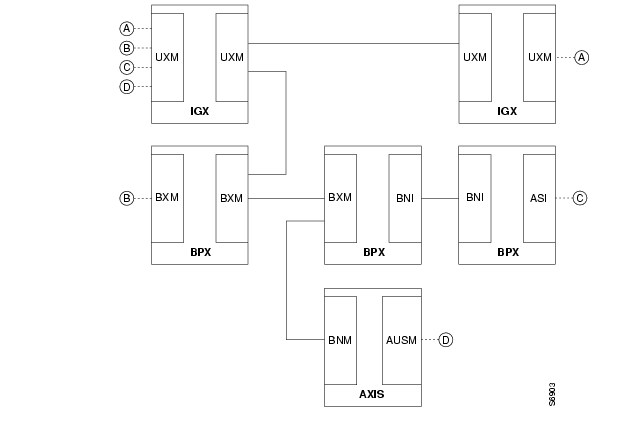
The network carrying only ATM traffic appears in . Each UXM trunk card in connects to either another UXM trunk card or a BXM operating as a trunk. The ATM UNI ports are the UXM port cards (for connection A), the BXM operating in port mode (for connection B), the ASI (for connection C), and the BXM feeder trunk (for connection D). Connection D is a two-segment connection. One segment of connection D exists between the BNM and AUSM on the Cisco MGX 8220 shelf, and the other segment exists between the BXM and the UXM UNI port.
Figure 3-6 UXMs in a Network With Pure ATM Traffic
A network with ATM traffic and FastPacket-based traffic appears in . Connections A and B are ATM connections that terminate on UXM UNI port cards and a BXM operating as a UNI port. Connection C is a Frame Relay connection between a UFM and an FRM. Connection D is a voice connection between a CVM and CDP. Connection E is a local connection (DAXCON) between a UFM and a UXM UNI port on the same node. For connections C-E, the gateway function of the UXM packs and unpacks the FastPackets into and out of the ATM cells.
Figure 3-7 UXMs in a Network With Heterogeneous Traffic
UXM Trunk Features
The following list broadly identifies the features of a UXM trunk. After the bulleted list, the remaining sections of this introduction contain tables that list the features on particular topics, such as interworking. Actual descriptions of the features appear in the section titled " The UXM in Trunk Mode."
•
•
Note
•
•
•
•
•
•
•
•
UXM Interfaces
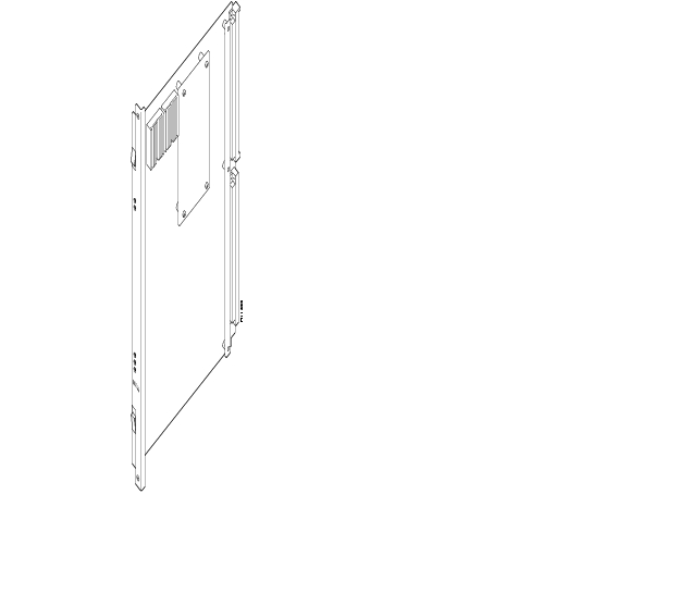
is a list of the UXM back cards. shows the UXM front card. defines all possible combinations for the states of the front card status LEDs (Fail, Active, and Standby).
Table 3-11 Back Cards for the UXM
Figure 3-8 UXM Front Card
Table 3-12 UXM Status LEDs
Maximum Number of UXMs
Switch software limits the number of logical trunks and ports on an IGX switch. The maximum number of UNI or NNI ports in an IGX switch is 64. The maximum number of logical trunks is 32. To determine the number of each logical type in the switch, add the number of ports on multiport cards and single-port cards. These sums cannot exceed 64 ports and 32 trunks. For example, using exclusively 2-port OC3 trunks, you could install:
2 trunks per card x 16 OC3 UXMs=32 trunks
Switch software monitors the number of logical ports and trunks, not the number of UXMs. Therefore, the software keeps you from activating an excessive number of lines or trunks on the node rather than flagging the presence of too many cards.
Y-Cabled UXM Redundancy
The UXM features hot standby as a part of its Y-cable redundancy capability. With hot standby, the redundant card receives the configuration information as soon as you finish specifying redundancy. The standby card also receives updates to its configuration as the active card configuration changes. Hot standby lets the backup card go into operation as soon as necessary rather than waiting for the NPM to download the configuration.
Y-cable redundancy requires that both cards are active and available before you set up redundancy. Use StrataView Plus or the CLI commands uptrk, addtrk, then addyred. (See also descriptions of addyred, delyred, dspyred, and ptyred in the Cisco WAN Switching Command Reference.)
Switchover to a Redundant UXM
If the card fails, a switchover occurs to a Y-cabled, redundant UXM card set if available. If the switchover occurs, the primary UXM acquires failed status, and the Fail LED turns on.
Card Mismatch
The UXM supports two types of card mismatch notification. The notification common to all cards occurs when you connect an unsupported back card to the front card. The mismatch notification unique to the UXM occurs if you attach a supported back card but one that has a different interface or a smaller number of the correct line types than what the UXM previously reported to software.
The UXM informs switch software of the number and type of interface ports when you first activate a UXM. Software retains the back card configuration data if you remove it. If you subsequently attach a card with fewer ports, switch software flags a mismatch. Replacing a back card with more ports of the same line type or exchanging SMF and MMF OC3 (STM1) cards is not a mismatch. To change the interface that software has on record, you must first down the card then re-activate it.
The UXM as a Clock Source
A UXM line or trunk can be the clock source for the node. Use the dspclksrcs command to display available clock sources, dspcurclk to show the current clock source, and cnfclksrc to specify a new clock source. To clear clock alarms, use clrclkalm.
Cellbus Bandwidth Usage
The Cellbus consists of four operational lanes plus one backup lane. (The backup lane becomes active if a lane fails.) The FastPacket-based cards can use only one lane and communicate only in FastPackets. If a FastPacket-based card controls the Cellbus, no ATM cells can be on the Cellbus.
When the UXM has control of the Cellbus, it can pass any of the following:
•
•
•
Switch software monitors and computes Cellbus bandwidth requirements for each card in the Cisco 8400-series switches. For the UXM alone, you can change its Cellbus bandwidth allocation. (You cannot view or alter bandwidth allocation for other cards.) The unit of measure for the ATM cell and FastPacket bandwidth on the Cellbus is the universal bandwidth unit (UBU).
Switch software allocates a default number of UBUs for the card when the UXM identifies the back card interface to switch software. If you remove a card, switch software reserves the current Cellbus bandwidth allocation for that card. If, as you add more connections, the load approaches oversubscription, switch software displays a warning message. Regardless of the warning message, Cisco advises you to monitor bandwidth allocation and allocate more UBUs for the card to avoid oversubscription.
For the UXM, switch software allocates enough bandwidth to meet the requirements for the minimum cell rate (MCR) and therefore does not accommodate burstiness. Therefore, you must know the UXM bandwidth requirements to determine if you should change its UBU allocation. Monitor the bandwidth requirements after you build the network and during normal operation. On the CLI, the applicable commands are cnfbusbw and dspbusbw.
You can raise, lower, or check a UXM's UBUs with cnfbusbw. The cnfbusbw privilege level is 0—superuser. To check a UXM's UBUs, use dspbusbw or cnfbusbw. Any user can use dspbusbw. Each command's display provides the information you need to determine if you must increase the UBUs on a particular UXM. The only value you can change is allocated bandwidth. An example display for cnfbusbw appears in Figure 3-9. The card-based default and maximum Cellbus bandwidth for each interface appears in . Note that FastPackets require substantially less Cellbus bandwidth than ATM cells. The FastPacket requirements in the figure and table reflect the restriction of FastPackets to one lane and the maximum processing rate of the gateway on the UXM.
The values you can view with the cnfbusbw and dspbusbw commands are:
•
•
•
•
•
Figure 3-9 Example Display for cnfbusbw
StrataCom TN Cisco IGX 16 9.1 Apr. 7 1998 03:15 GMTBus Bandwidth Usage for UXM card in slot 5 Last Updated on 04/07/98 03:15:42FPkts/sec Cells/sec UBUsMinimum Reqd Bandwidth: 0 100100 26Average Used Bandwidth: 0 0 0Peak Used Bandwidth: 0 0 0Maximum Port Bandwidth: - 288000 72Allocated Bandwidth: 1(Cell Only): - 4000(Cell+Fpkt): 2000 3000(Fpkts / 2 + Cells) <= 4000Reserved Bandwidth: - 4000 1This Command: cnfbusbw 5Allocated UBU count:Table 3-13 Cellbus Bandwidth Allocation for UXM Interfaces
Planning for Cellbus Bandwidth Allocation
With the Network Modeling Tool™ (NMT), you can use the projected load for all UXMs in the network to estimate their Cellbus requirements. During normal operation, you can use StrataView Plus to obtain the trunk and port statistics then decide whether to use cnfbusbw to increase the UBU allocation. If you are using only the CLI, you would need to establish a virtual terminal (vt) session to each node then execute dspbusbw or cnfbusbw.
Calculating Cellbus Bandwidth Changes
To determine how many UBUs are necessary, use the values for average bandwidth used (see Figure 3-9) in the following formula:
In most circumstances, the fps and cps values from average bandwidth used are sufficient. The peak bandwidth used values are primarily informational.
The information in provides the ranges for the interface type. Note that, if you do the math according to the formula, you see that the value in the cells-alone column of equals the result of adding half the FastPacket value to the cell value in the cells plus FastPackets column.
When you use dspbusbw, a yes/no prompt asks if you want firmware to retrieve the usage values. If you enter a "y," the UXM reads—then clears—its registers and thus restarts statistics gathering. If you enter an "n," switch software displays the current values that reside in control card memory (on the NPM). The values in memory come from the last update from the UXM.
ATM Across a Public ATM Network
The UXM can support trunking across a public ATM network such that both virtual channel connections (VCCs) and virtual path connections (VPCs) traverse a single virtual path trunk. This feature lets you map multiple trunks to a single port of an NNI. The NNI connects to either a public or private ATM network. The virtual trunk package is a lower-cost alternative to leased circuits but still has the full set of Cisco ATM traffic management capabilities. This application requires two UXMs and a clock from an external source. The rates can be OC-3/STM-1, T3/E3, or T1/E1.
Figure 3-10 UXMs Configured for a Public ATM Network
Note the following characteristics of this form of trunking across a public network:
•
•
•
Refer to as you read the steps for the following example set-up:
Step 1
•
•
•
•
Step 2
Step 3
Routing Over Cell Trunks Only
You can specify trunk cell routing only as an option when you add a connection between UXM, ASI, or BXM ports. When you enable trunk cell routing, switch software routes across only the cell-based trunk cards BNI, BXM, and UXM: no conversion to FastPackets occurs on the route. If you disable trunk cell routing, the routing process may select a FastPacket-based trunk and so decrement the number of available gateway connections. Also, using a FastPacket-based trunk may result in increased network delays. Therefore, enabling trunk cell routing is the preferred choice when you add a connection at a BNI, BXM, or UXM.
If you add connections at other port cards, such as a UFM or ALM/A, switch software does not display the trunk cell routing option.
On the CLI, the addcon prompt for this option appears as "trunk cell routing restrict y/n?" It appears after you enter either the ATM class of service or after you finish specifying all the individual bandwidth parameters that apply to the current connection type. You can specify whether the default for trunk cell routing is "Yes" or "No" through the cnfnodeparm (superuser) command.
The UXM in Trunk Mode
The UXM trunk can communicate ATM cells that originated at an ATM endpoint or—through its on-board gateway functionality—FastPacket-based traffic such as voice, data, and Frame Relay. A UXM trunk can connect to the following trunk cards:
•
•
Types of Supported Traffic
As previously stated, the UXM trunk can connect to only another UXM trunk or a BXM trunk. On the other hand, the types of traffic that traverse a UXM trunk can originate at ATM ports or other types of ports. The types of traffic that a cell on a UXM trunk can carry appear in and . shows the supported traffic that terminates on ATM ports. shows the traffic types that ATM cells can carry where the payload originated as a FastPacket.
Table 3-14 Connections From ATM Endpoints
CBR.1
VBR.1, VBR.2, VBR.3
ABR with VSVD
ABR without VSVD
ABR with ForeSight
UBR.1, UBR.2
Table 3-15 Traffic From FastPacket-Based Cards
Timestamped
Non-timestamped
Voice
Bursty data A
Bursty data B
High priority
CBR, VBR, ABR
Types of Connections on a UXM Trunk
This section introduces the connections that a UXM trunk supports. The context of each description is the trunk rather than the connection endpoints. The purpose of these descriptions is not only to inform but also help you plan the network. Some definitions overlap because a connection may qualify as more than one type.
•
•
•
•
•
•
Operating as a trunk, the UXM carries up to 8000 connections. No more than 4000 of these can be trunk connections. A via connection can be either a cell-type or a gateway-type.
Because network messages use gateway channels, they subtract from the total number of available gateway connections. For each active port, the UXM reserves 270 gateway connections for networking regardless of the interface type. Therefore, with a fully-utilized 8-E1 or 8-T1 back card, the UXM reserves up to 2160 connections. Because these numbers potentially represent a very significant reduction in the number of gateway connections for user-data, switch software lets you specify a maximum number of active ports on the back card. The most applicable interfaces for this capability are the T1 and E1 ports, especially with Inverse Multiplexing Over ATM (IMA). See the section " Inverse Multiplexing Over ATM" for the description of IMA.
You can specify the maximum number of logical trunks that can be active on a card through StrataView Plus or the CLI. The applicable CLI command is cnftrkport. For example, if you intend an eight-port card to have two logical (IMA) trunks, you can use cnftrkport to specify a maximum number of two trunks. Software would therefore reserve 540 connections for network messages rather than the 2160 connections if you did not specify a maximum.
Inverse Multiplexing Over ATM
Inverse Multiplexing Over ATM (IMA) lets you group physical T1 or E1 lines to form a logical trunk. A logical trunk consisting of more than one T1 or E1 line supports connections with data rates that are much higher than the T1 or E1 rate. System software lets you specify IMA so that one or more physical lines within the logical trunk can serve as a backup if a line fails.
IMA characteristics are as follows:
•
•
•
•
•
•
To specify the range of ports for an IMA trunk, you can use either StrataView Plus or the CLI. To define an IMA trunk on the CLI, use the uptrk command in the following format:
uptrk <slot>.<start_port>-<end_port>
For example, you could enter uptrk 8.1-4. Subsequently, you would refer to this logical trunk by using only the slot number and first port number—8.1 in this example—when you use other commands, such as addtrk, deltrk, cnftrk, and so on. Commands for viewing IMA information also include dspportstats, dspphyslns, and dspphyslnstathist.
When you configure an IMA trunk through StrataView Plus or the cnftrk command, you enter the number of retained links. The retained links is the number of ports that must remain active for the IMA trunk itself to remain active. If a physical line goes out of service yet the number of active lines is at least as great as the retained links value, the IMA trunk remains active even though the node goes into major alarm. Also, the available load bandwidth is adjusted according to physical line status, so the switch does not reroute connections after a line failure unless the used bandwidth becomes greater than the available bandwidth.
With the Automatic Link Disable option, you can specify a failure transition rate that causes a physical port within the logical trunk to acquire failed status. If a specified number of failures occur within a specified time window, the physical line becomes inactive. After a user-specified wait period passes, the node attempts to re-activate the line and start another window for monitoring error transitions. This option is available only if the number of retained links is less than the number of physical lines in the logical trunk.
The transmit and receive rate of an IMA trunk is the sum of all physical lines minus the IMA protocol overhead. The overhead for up to four lines is one DS0. Using the previous IMA trunk example, the maximum rates are as follows:
for trunk 8.1-4 (with T1 lines),
TX rate = Rx rate = 24 * 4 DS0s - 1 DS0 = 95 DS0s
You could configure the line receive rate to be the maximum bandwidth allowed on this trunk:
total bandwidth = RX rate = 95 DS0s
However, if a physical line fails (and the number of retained links are still active), the switch adjusts the total bandwidth. Using the example IMA trunk consisting of four physical T1 lines:
total bandwidth is 95 DS0s - 24 DS0s = 71 DS0s
Upon a physical line failure, connection rerouting may occur. The switch reroutes connections if the used bandwidth is greater than the new, adjusted total bandwidth. The dsptrks command shows the logical trunk's alarm status, and dspphyslns shows status of the physical lines. When a physical line is repaired, any failed connections are rerouted.
To diminish the possibility of connection rerouting after a physical line failure, set the Line Receive Rate to be at or below the aggregate rate for the retained links rather than the total number of lines in the IMA trunk. You could, in the preceding example, configure the receive rate for 71 DS0s.
Activation and Configuration of a UXM in Trunk Mode
When you insert a new UXM into the backplane or apply power to the IGX node, UXM firmware reports the card type and number of physical lines on the back card. Switch software can then determine the allowed range and characteristics of trunks for you to configure. Software thus prevents you from exceeding the maximum number of trunks on the switch as you activate them through either StrataView Plus or uptrk on the CLI.
shows the trunk characteristics you can configure for each interface type through either StrataView Plus or the cnftrk command on the CLI. also shows the fixed parameters.
Table 3-16 Configurable Trunk Characteristics
Alarms for Physical Lines and Logical Trunks
Variations exist in the way switch software supports alarms for physical lines and logical trunks for a trunk-mode UXM. The following list summarizes the approach to physical lines and trunks:
•
•
•
•
•
•
•
The physical layer trunk alarms include LOS, LOF, AIS, Yel, LOP, Path AIS, and Path Yel. To view these alarms, use the dspphysln command. When you execute dspphysln, any existing alarms appear as the physical line status. For a trunk with one physical line (such as an OC3 trunk or T1/E1 without IMA configured), the integrated alarm status is also shown by the dsptrks command.
You can enable the physical line statistical alarm on the CLI through the cnfphyslnalm command. You can display existing alarms through the dspphyslnerrs command and clear the alarms through the clrphyslnalm command.
To enable or disable the physical line or trunk statistical alarms, use cnftrkalm command. To display any outstanding alarms, use dstrkerrs. To clear the statistical alarms, use clrtrkalm.
To see the physical line and trunk statistical alarm types that apply to the UXM, enter the commands for configuring the alarms.
In summary, the applicable commands are dspphyslns, dspphyslnerrs, clrphyslnalm, cnflnalm, dsptrks, dsptrkerrs, cnftrkalm, clrtrkalm, dspalms.
Trunk Statistics for Troubleshooting
In Release 9.1, switch software separates the UXM trunk statistics into physical statistics and logical statistics. (This separation is a deviation from other schemes for trunk statistics management.) The commands in this section are useful primarily for troubleshooting.
The CLI commands cnfphyslnstats, dspphyslnstatscnf, and dspphyslnstathist apply to the statistics for physical lines within an IMA trunk. You can enable the physical line statistics by using cnfphyslnstats, display the configuration for statistics with dspphyslnstatcnf, and display the statistics themselves with dspphyslnstathist.
The logical trunk statistics includes Qbin statistics, VI statistics, and gateway statistics. To enable statistics by using the StrataView Plus, you must use the TFTP mechanism. To configure the logical trunk statistics through the CLI, use cnftrkstats. The dsptrkstatcnf command shows the configuration of the trunk statistics. To display the logical trunk statistics, use dsptrkstathist. These three commands primarily apply to debugging.
Software also supports statistics for trunk ports. Use the dspportstats command to display these statistics.
In summary, the following commands let you manage trunk statistics: cnfphyslnstats, cnftrkstats, dspphyslnstatcnf, dspphyslnstathist, dsptrkstatcnf, dsptrkstathist, and dspportstats.
Summary Statistics
You can view summary statistics for a UXM trunk through StrataView Plus or the CLI. The CLI commands are dspportstats and dsptrkstats.
With dspportstats, you can view:
•
•
•
With dsptrkstats, you can view:
•
•
•
UXM Interface Cards
This section provides basic information on the interface back cards for the UXM. The information consists of a general description, an illustration of the card faceplate, and a table describing the connectors and status LEDs. For details on the line technology of each type of interface, see the appendix titled " ."
Note
The model numbers of the back cards and the order of their appearance are:
•
•
•
•
•
•
•
•
•
•
•
•
•
OC-3/STM1 Back Cards
The OC3/STM1 back cards for the UXM have the single-mode fiber (SMF) and multi-mode fiber (MMF) connections. The cards are:
•
•
•
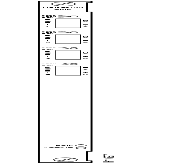
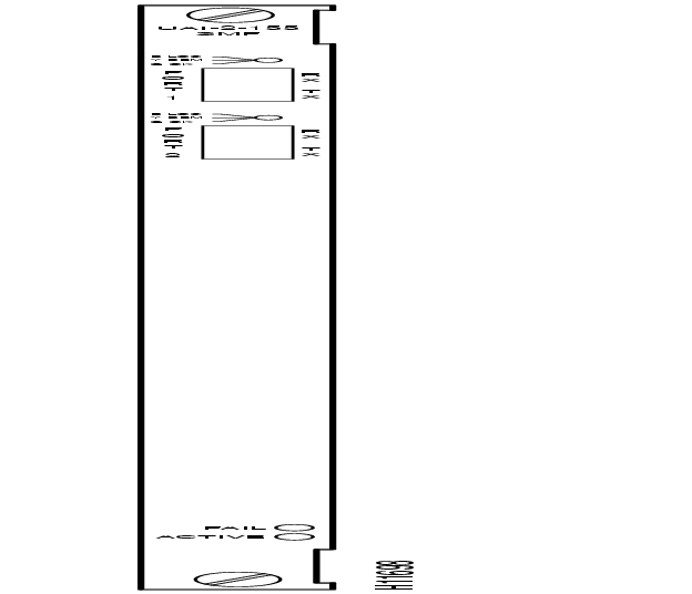
As indicated by the "2" or the "4" in the model number, these cards have two or four transmit and receive connectors. Each line has a tri-color LED whose color indicates its status. Each card also has a red Fail LED and a green Active LED to indicate the status of the card. lists the connectors and LEDs. shows the four-port OC3/STM1 card. The SMF and MMF versions appear the same. shows the two-port OC3/STM1 card. For technical data on OC3/STM1 lines, see the appendix titled "System Specifications."
Table 3-17 Connectors and LEDs for SMF and MMF Back Cards
Figure 3-11 BC-UAI-4-155-SMF Faceplate
Figure 3-12 BC-UAI-2-155-SMF Faceplate
T3 Back Cards
The T3 back cards for the UXM are BC-UAI-6-T3 and BC-UAI-3-T3. These cards have six and three pairs of BNC connectors, respectively. Each port has a tri-color LED whose color indicates its status. Each card also has a red Fail LED and a green Active LED to indicate the status of the card. lists the connectors and LEDs. show the six-port T3 card. shows the three-port T3 card. For technical data on T3 lines, see the appendix titled "System Specifications."
Table 3-18 Connectors and LEDs for BC-UAI-6-T3 and BC-UAI-3-T3
Figure 3-13 BC-UAI-6-T3 Faceplate
Figure 3-14 BC-UAI-3-T3 Faceplate
E3 Back Cards
The E3 back cards for the UXM are the six-port BC-UAI-6-E3 and the three-port BC-UAI-3-E3. These cards have six and three pairs of connectors, respectively. Each line has a tri-color LED whose color indicates its status. Each card also has a red Fail LED and a green Active LED to indicate the status of the card. lists the connectors and LEDs. show the six-port card. shows the three-port card. For technical data on E3 lines, see the appendix titled "System Specifications."
Table 3-19 Connectors and LEDs for BC-UAI-6-E3 and BC-UAI-3-E3
Figure 3-15 BC-UAI-6-E3 Faceplate
Figure 3-16 BC-UAI-3-E3 Faceplate
T1 Back Cards
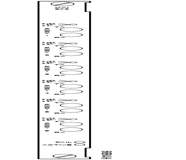
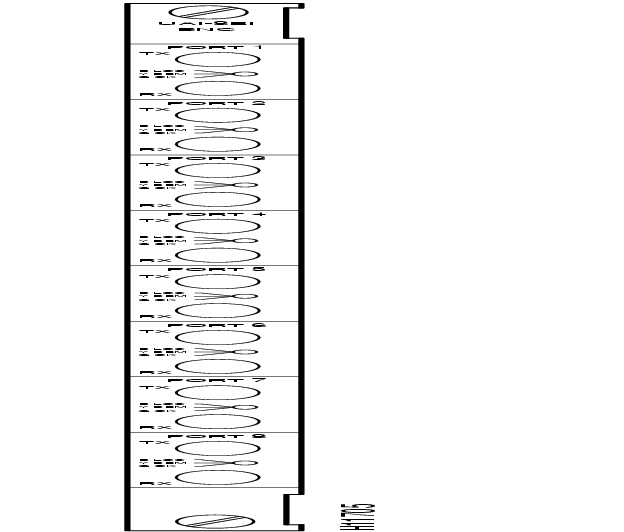
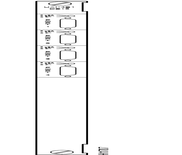
The T1 back cards for the UXM are BC-UAI-8-T1 and BC-UAI-4-T1. These cards have eight and four DB15 lines, respectively. Each line has a tri-color LED whose color indicates its status. If a card failure occurs, all the LEDs turn red. lists the connectors and LEDs. show the eight-port T1 card. shows the four-port T1 card. For technical data on T1 lines, see the appendix titled "System Specifications."
Table 3-20 Connectors and LEDs for BC-UAI-8-T1 and BC-UAI-4-T1
Figure 3-17 BC-UAI-8-T1 Faceplate
Figure 3-18 BC-UAI-4-T1 Faceplate
E1 Back Cards
The E1 back cards for the UXM are:
•
•
•
•
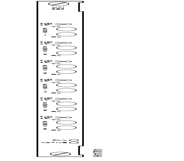
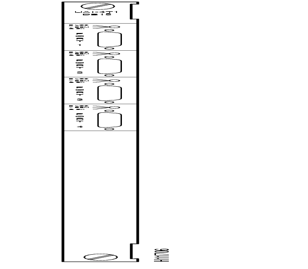
As the model numbers indicate, the eight and four-port E1 cards can have either BNC or DB15 connectors. Each line has a tri-color LED whose color indicates its status. If a card failure occurs on the back card, all LEDs turn red. lists the connectors and LEDs. show the eight-port E1 card. shows the four-port T1 card. For technical data on E1 lines, see the appendix titled "System Specifications."
Table 3-21 Connectors and LEDs for BC-UAI-8-E1 and BC-UAI-4-E1
Figure 3-19 BC-UAI-8-E1 DB15 Faceplate
Figure 3-20 BC-UAI-8-E1 BNC Faceplate
Figure 3-21 BC-UAI-4-E1 DB15 Faceplate
Figure 3-22 BC-UAI-4-E1 BNC Faceplate
Network Trunk Module (NTM)
The Network Trunk Module (NTM) enables FastPacket transmission on a trunk. NTM functions include the following:
•
•
•
•
•
•
•
Note
An NTM can occupy any available front service card slot in the range 3 to 32. The choice of back card depends on the trunk interface type.
For fractional T1 trunk lines, the NTM and BC-T1 card set can provide the interface. A fractional trunk interface uses a group of 64-Kbps channels to create a partial T1 trunk. For example, a 512-Kbps fractional T1 trunk might use every third channel among channels 1-24. The user makes the channel assignments. For the clock rate, fractional trunks use the basic trunk frequency (such as 1.544 Mbps for T1).
Fractional E1 is the same as fractional T1 except that the channels are 1-15 and 17-31 (0 and 16 reserved), and the clock rate is 2.048 Mbps.
The NTM supports subrate trunks if a BC-SR back card and appropriate local bus are present. Subrate trunks interface to the transmission facility at rates in the range 256 Kbps-2.048 Mbps. Three interface connections are possible: EIA/TIA-449, X.21, and V.35.
Y-Cable Redundancy for the NTM
You can configure the NTM for 1:1 redundancy by using a second, identical, card group in an adjacent slot and a Y-cable to connect the card sets. All NTM back cards support redundancy.
NTM Status
The faceplate of the NTM has four LEDs. The first two in the following list apply to the NTM front card. Each of the other two LEDs is a summary alarm for the back cards. Their significance is:
•
•
•
•
For details on the significance of LEDs, see the Cisco IGX 8400 Series Installation manual.
The alarms and line conditions that the NTM monitors include those in the list that follows. To view errors on a trunk, use the dsptrkerrs command. To see a list of the (user-specified) errors that dsptrkerrs can display, use dsptrkstatcnf.
•
•
•
•
•
•
•
T1 Interface Card (BC-T1)
The T1 Trunk Interface Card (BC-T1) card terminates a single 1.544 Mbps T1 trunk line on the NTM. The BC-T1 can reside in any rear slot 3-8 in an IGX 8410, 3-16 of the IGX 8420, or 3-32 of the IGX 8430. The BC-T1 connects directly to the NTM.
The BC-T1 provides the following:
•
•
•
•
•
•
•
B8ZS supports clear channel operation because B8ZS eliminates the possibility of a long string of 0s. B8ZS is preferable whenever available, especially on trunks.
The BC-T1 supports two clock modes. The clock modes are normal clocking and loop timing. You select the mode through software control. With normal clocking, the node uses the receive clock from the network for the incoming data and supplies the transmit clock for outgoing data. The node can use the receive clock to synchronize itself with the network.
With loop timing, the node uses the receive clock from the network for the incoming data and redirects this receive clock to time the transmit data.
BC-T1 Faceplate Description
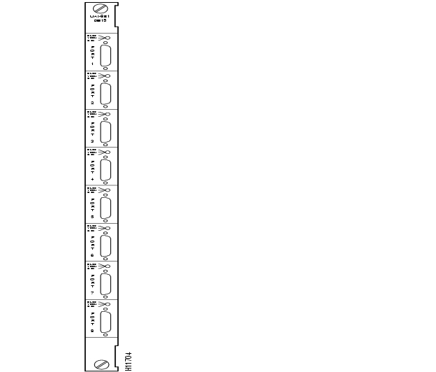
and provide information on the faceplate of the BC-T1. When you correlate the descriptions in the table with the callouts in the figure, read from the top of the table to the bottom. The standard port connector is a female DB15.
Figure 3-23 BC-T1 Faceplate
Table 3-22 BC-T1 Connections and Status LEDs
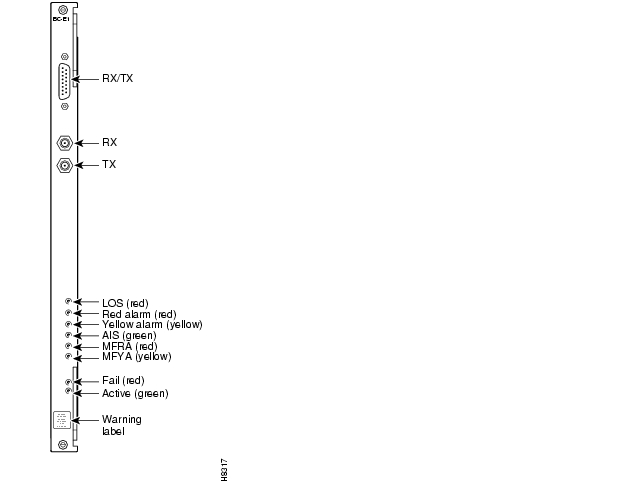
E1 Interface Back Card (BC-E1)
The E1 Trunk Interface Card (BC-E1) provides an E1 trunk interface for the Network Trunk Module (NTM). The BC-E1 connects directly to the NTM and can reside in any rear slot 3-8 in an IGX 8410, 3-16 in an IGX 8420, or 3-32 in an IGX 8430. The BC-E1 provides the following:
•
•
•
•
•
•
•
•
•
The BC-E1 supports two clock modes. The clock modes are normal clocking and loop timing. You select the mode through software control. With normal clocking, the node uses the receive clock from the network for the incoming data and supplies the transmit clock for outgoing data. The node can use the receive clock to synchronize itself with the network.
With loop timing, the node uses the receive clock from the network for the incoming data and redirects this receive clock to time the transmit data.
Statistics are kept on most line errors and fault conditions, including the following:
•
•
•
•
•
•
•
•
shows and lists status LEDs and connections on the BC-E1 faceplate. When you correlate the table and figure items, read from the top to the bottom.
Figure 3-24 BC-E1 Faceplate
Table 3-23 BC-E1 Connections and Status LEDs
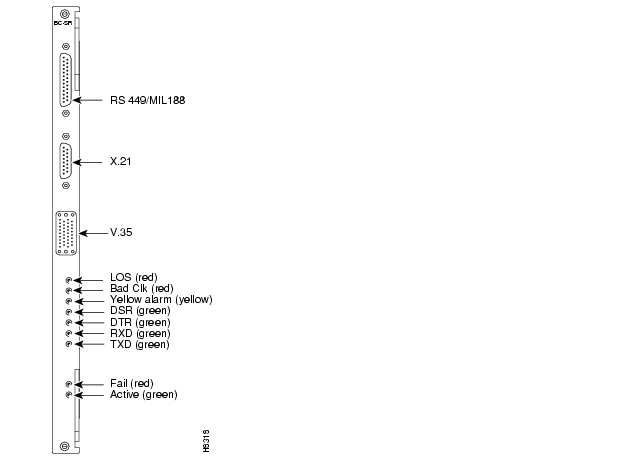
Subrate Interface Card (BC-SR)
The Back Card/Subrate (BC-SR) terminates subrate trunks on the NTM. A subrate trunk uses part of the E1 or T1 bandwidth. The BC-SR typically functions in tail circuits or where little traffic exists.
A subrate trunk facility interface operates in DCE mode, and the subrate channel functions like a synchronous data channel. Therefore, the IGX BC-SR always operates in DTE mode. Only leased lines are supported (no dial-up lines). Subrate trunks cannot pass clock signals between nodes.The BC-SR provides the following:
•
•
•
•
•
and describe the BC-SR faceplate. When you correlate the figure and table, read from the top down.
lists the data signals and EIA leads supported by the subrate interface.
Figure 3-25 BC-SR Faceplate
Table 3-24 BC-SR Connections and Status LEDs
Table 3-25 Data and Control Leads Supported with BC-SR
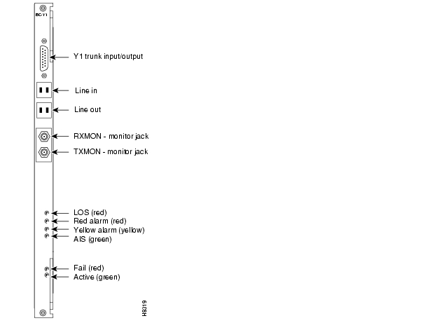
Y1 Interface Back Card (BC-Y1)
The BC-Y1 back card provides a Japanese Y1 trunk interface for an NTM. The BC-Y1 can reside in any rear slot 3-8 in an IGX 8410, 3-16 in an IGX 8420, or 3-32 in an IGX 8430. The BC-Y1 provides:
•
•
•
•
•
•
•
The BC-Y1 supports two clock modes. These are normal clocking and loop timing. The system operator selects the mode through software control. Normal clocking uses the receive clock from the network for incoming data and supplies the transmit clock for outgoing data. This clock can be used to synchronize the node.
Loop timing uses the receive clock from the network for the incoming data and turns the receive clock around for timing the transmit data.
and provide descriptions of the BC-Y1 status LEDs and connections on the faceplate. When you correlate the items in the figure and table, read from the top to the bottom.
Figure 3-26 BC-Y1 Faceplate
Table 3-26 BC-Y1 Connections and Status LEDs
Broadband Trunk Module (BTM)
The BTM card set provides an Asynchronous Transfer Mode (ATM) trunk interface. With a BTM, the switch can use the standard ATM cell relay protocol on the line. The BTM has a maximum throughput of 16 Mbps. Therefore, its typical use is to have multiple T1 or E1 channels up to a maximum of 8 channels. The BTM's compatibility with T3/E3 trunks supports migration of the node towards T3/E3 rates in T1/E1 increments. In addition, the BTM supports optional E2 and HSSI interfaces. The maximum E2 rate is 8 Mbps. A HSSI back card supports a rate of 50.84 Mbps, so a BTM with a HSSI back card can achieve a burst rate of up to 50.84 Mbps. Note that the use of a HSSI interface requires an external, inverse multiplexer that serves as a DCE and provides clocking.
The BTM card set consists of the BTM front card and either an AIT-T3, AIT-E3, AIT-E2, AIT-HSSI, or BTI-E1 back card. The card set works in the following arrangements:
•
•
•
•
LED Indicators and Alarms
The faceplate of the BTM has four LEDs. The Active LED indicates the card is active and functioning. A BTM card failure triggers the Fail LED. The other two LEDs are a summary alarm for the AIT back card conditions. A yellow Minor LED indicates either a fault that does not interrupt service or that error statistics have exceeded a preset threshold. A red Major LED indicates a service-affecting failure. See .
Maintenance and Troubleshooting
The BTM card set requires no maintenance. If a card has a solid or a (confirmed) intermittent failure, replace it. The only indicators on the BTM faceplate are the Active and Fail LEDs. For purposes of troubleshooting, you should view the BTM/AIT card set as a trunk. The tstcon command does not work on a BTM because the card cannot be isolated from the IGX or the other, connected BTM.
A trunk loopback test runs when the BTM detects an integrated alarm. The loopback test verifies if the line or the card is faulty. A loopback test "pass" means that the line is faulty, and a line alarm is indicated. A loopback test "fail" means that the card is faulty. In the case of a faulty card, a switch to a Y-Cable equipped redundant card occurs if available.
Y-Cable Redundancy
The BTM card set supports Y-cable redundancy on ATM trunks in IGX to IGX, IGX to IPX and IGX to BPX applications. Y-cable redundancy requires that both cards are upped and added through either StrataView Plus or the CLI before you assign redundancy. The CLI commands are uptrk, addtrk, and addyred. (In the Cisco WAN Switching Command Reference, see descriptions of addyred, delyred, dspyred, and ptyred.)
Switchover to a Redundant BTM
If the card fails, a switchover occurs to a Y-cabled, redundant BTM trunk card set if one is available. If the switchover occurs, the primary ATM trunk card acquires failed status, and the red Fail indicator turns on. If Y-cable redundancy is not available and the failed trunk is the clock source, the node switches to another clock source and marks the line as a failed clock source.
Figure 3-27 BTM Faceplate
Descriptions of BTM Back Cards
The back card provides the interface to the trunk line and performs all necessary CRC generation and checking. The back card faceplate has six LEDs. They indicate the status of the port and various alarm conditions. Refer to the back card figures and tables accompanying each card description for details. The BTM back cards are as follows:
•
•
•
•
•
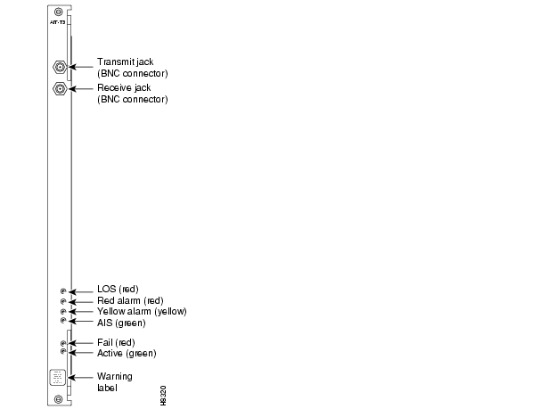
AIT-T3 Back Card
The AIT -T3 back card has two BNC connectors and six LED indicators, as shows. lists these faceplate items. When you correlate the items in the figure and table, read from the top.
Figure 3-28 AIT-T3 Back Card Faceplate
Table 3-27 AIT-T3 Connections and Indicators
BTI-E1 Back Card
The BTI-E1 back card provides an E1 trunk interface for the BTM front card. It has unbalanced and balanced connectors for line connections. In general, the functions of the BTI-E1 are to:
•
•
•
•
The tables in this section provide more detailed characteristics of the BTI-E1. shows the BTI-E1 faceplate. describes the connectors and status LEDs. lists the general E1 line characteristics of the BTI-E1. lists the ATM characteristics of the BTI-E1. lists the trunk parameters you can configure by using cnftrk.
Figure 3-29 BTI-E1 Back Card Faceplate
Table 3-28 BTI-E1 Connections and Indicators
shows the E1 line specifications for the BTI-E1. For a more detailed list of E1 characteristics, see the appendix titled " ."
Table 3-29 Line Specifications for the BTI-E1
describes the ATM interface parameters for the BTI-E1.
Table 3-30 ATM Interface Specifications
The cnftrk command lets you configure parameters for the interface provided by the BTI-E1. shows the particular ranges and defaults for the BTI-E1.
Table 3-31 BTI-E1 Configuration
AIT-HSSI Back Card
The AIT-HSSI back card supplies a single HSSI interface to the AIT trunk. For its implementation, the AIT-HSSI requires an external DSU such as an inverse mux or a fractional T3 DSU. shows the faceplate of the AIT-HSSI. The HSSI connector has 50 pins.
The range of bit rates for the AIT-HSSI on a BTM is 4 Mbps to 16 Mbps. The range of rates is across aggregated T1 channels. The command that configures the rate is cnftrk. The dsptrkcnf command displays the existing parameters for a trunk. For specifications on HSSI, see the appendix titled " ."
Figure 3-30 AIT-HSSI Faceplate
AIT-E2 Back Card
The AIT-E2 back card supplies a single E2 interface to the 16-Mbps BTM front card. The line rate is 8.448 Mbps. The AIT-E2 operates between only Cisco WAN switches, so it does not support a UNI interface. For specifications on this E2 line, see the appendix titled " ." shows the AIT-E2 faceplate.
Figure 3-31 AIT-E2 Faceplate
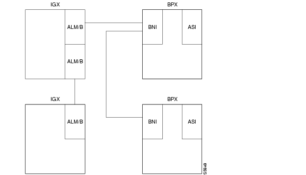
ATM Line Module B (ALM/B)
The ATM Line Module B (ALM/B) card set provides a trunk with a full T3 or E3 rate. Back cards for the ALM/B are the BC-UAI-1T3 and the BC-UAI-1E3. They support either a single T3 trunk or a single E3 trunk. For characteristics of T3 and E3 trunks, see the appendix titled " ." For information on how to bring up an ALM/B trunk, refer to the Cisco IGX 8400 Series Installation manual. illustrates an ATM cloud using the ALM/B.
ALM/B Features
The ALM/B supports the following:
•
•
•
•
•
•
The ALM/B card set consists of the ALM/B front card and either a BC-UAI-1T3 or a BC-UAI-1E3. The card set works in the following arrangements:
•
•
•
•
Figure 3-32 ALM/Bs in a Network
Operating Modes
On a per-connection basis, the ALM/B operates in either simple gateway or complex gateway mode. Complex gateway supports network interworking. For a description of tiered networks, trunks, ATM protocols, and cell and header formats, refer to the Cisco System Overview.
The simple gateway loads 24-byte FastPacket cells into ATM cells in ways that are consistent with each application. (Each of the two FastPackets loaded into the ATM cell is loaded in its entirety, including the FastPacket header). For example, two FastPackets can be loaded into one ATM cell if both FastPackets have the same destination.
Complex gateway is supported by streaming the frame relay data into ATM cells, cell after cell, until the frame has been completely transmitted. Since only the data from the FastPacket is loaded, the Complex gateway is an efficient transmission mechanism. Additionally, discard eligibility information carried by the frame relay bit is mapped to the ATM cell CLP bit, and vice versa.
Maintenance and Troubleshooting
The ALM/B card set requires no maintenance. If an ALM/B card set has either a solid or an intermittent but confirmed failure, replace it. The only indicators on the ALM/B faceplate are the Active and Fail LEDs. For purposes of troubleshooting, you should view the ALM/B card set as a trunk. The tstcon command does not work on an ALM/B because the card cannot be isolated from the IGX or the other, connected trunk card set.
A trunk loopback test executes when the ALM/B detects an integrated alarm. The loopback test determines if the line or the card is faulty. A loopback test "pass" means the line is faulty, so a line alarm is flagged. A loopback test "fail" means the card is faulty. If a card is faulty and a Y-cabled secondary is available, a switch to the secondary card occurs.
LED Indicators and Alarms
The faceplate of the ALM/B has four LEDs. See .The Active LED indicates the card is active and functioning. An ALM/B card failure triggers the Fail LED. The other two LEDs are a summary alarm for the back card conditions. A yellow Minor LED indicates either a fault that does not interrupt service or that error statistics have exceeded a preset threshold. A red Major LED indicates a service-affecting failure.
Y-Cable Redundancy
The ALM/B card set supports Y-cable redundancy on ATM trunks in IGX-to-IGX, IGX-to-IPX and IGX-to-BPX applications. (In the Cisco WAN Switching Command Reference, see descriptions of addyred, delyred, dspyred, and ptyred.)
Y-cable redundancy requires that both cards are upped (uptrk) and added (addtrk) before you assign redundancy with the addyred command.
Switchover to a Redundant ALM/B
If the card fails, a switchover occurs to a Y-cabled, redundant ALM/B trunk card set if one is available. If the switchover occurs, the primary ATM trunk card acquires failed status, and the red Fail indicator turns on. If Y-cable redundancy is not available, the ATM trunk switches to another clock source and marks the line as a failed clock source.
Figure 3-33 ALM/B Faceplate
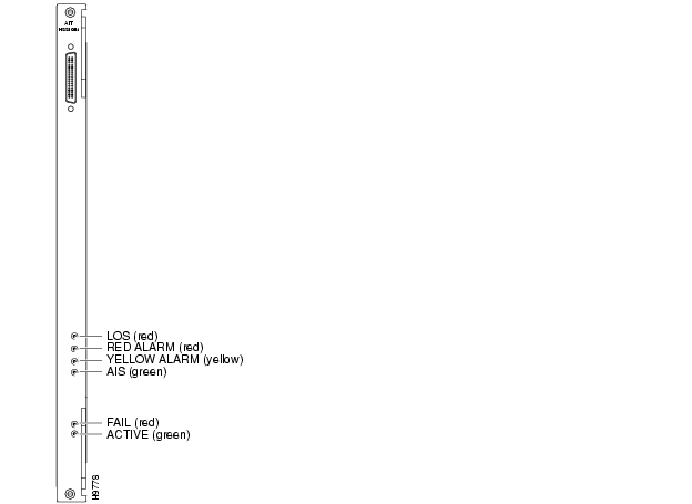
Interface Back Cards for the ALM/B
The back card provides the interface to the trunk line and performs all necessary CRC generation and checking. The following are the ALM/B back cards:
•
•
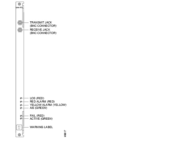
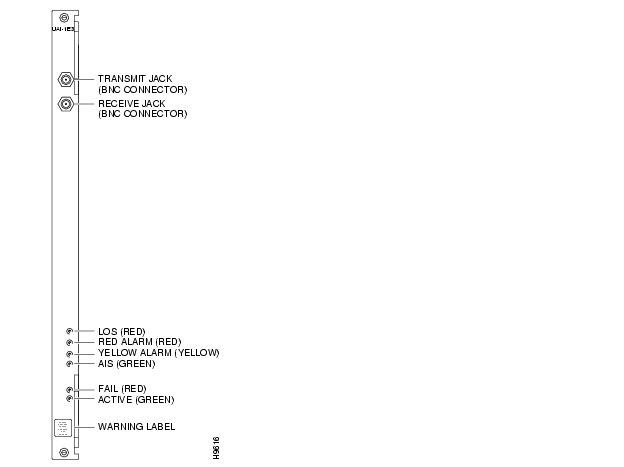
The trunk ports consist of one BNC connector for transmit data and one BNC connector for receive data. The back card faceplate has six LED indicators. The LEDs indicate the status of the port and various alarm conditions. See and for details on the T3 card and and for details on the E3 card. Correlate items in each figure and table as you read from the top down. For technical specifications on T3 and E3 lines, see the appendix titled " ."
Figure 3-34 BC-UAI-1T3 Faceplate
Table 3-32 BC-UAI-1T3 Connections and Indicators
Figure 3-35 BC-UAI-1E3 Faceplate
Table 3-33 BC-UAI-1E3 Connections and Indicators
![]()
![]()
![]()
![]()
![]()
![]()
![]()
![]()
Posted: Wed Aug 25 16:45:05 PDT 2004
All contents are Copyright © 1992--2004 Cisco Systems, Inc. All rights reserved.
Important Notices and Privacy Statement.