|
|

This chapter describes various types of networks or network applications that may be implemented with the Cisco WAN switching cell relay network switches, the Cisco BPX 8600 series broadband switch, the Cisco IGX 8400 series multiband switch, the Cisco IPX narrowband switch, the Cisco MGX 8220 edge concentrator, and associated equipment such as the Cisco 3800 and the FastPAD.
The Cisco BPX 8600 series broadband switch, Cisco IGX 8400 series multiband switch, and the Cisco IPX narrowband switch, which are sometimes referred to as nodes, are the basic network building blocks. The nodes are interconnected by transmission facilities called trunks. User data inputs to the network at nodes through various user devices.
This chapter contains the following:
Cisco WAN switching ATM networking products are used to provide the advantages of Asynchronous Transfer Mode technology in a variety of network applications:
One of the main advantages of ATM is its ability to integrate a wide variety of traffic types and provide a transport mechanism to equally support each of their unique requirements. ATM supports both constant bit rate and variable bit rate traffic equally well to open the door to multi-media networking.
ATM networks provide a suitable interface adaptation for each service type assuring the required amount of circuit bandwidth, the class of service, and the broadband aggregate capacity provided by the network ATM trunks.
This has already been successfully demonstrated over networks using the voice, data, video, and frame relay user interfaces currently available with the Cisco IPX narrowband switch, the Cisco 3800, the Cisco MGX 8220 edge concentrator, Cisco IGX 8400 series multiband switch, and the ATM connections to the Cisco BPX 8600 series broadband switch (). Since the Cisco IPX narrowband switch has always been a cell-based node, it handles multimedia inputs with a maximum of efficiency. The Cisco IGX 8400 series multiband switch provides all the capabilities of the Cisco IPX narrowband switch but with additional multiband and multiservice capabilities.
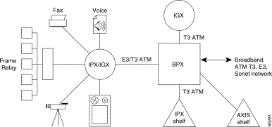
Another advantage of ATM technology is its scalability. The physical transmission facilities are separate from the various ATM data layers unlike other high-speed protocols such as FDDI. For example, an ATM backbone may be implemented initially with DS3 or E3 trunks operating over fiber or digital radio.
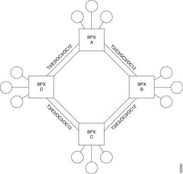
As network bandwidth requirements grow, the transmission facility may be upgraded to fiber operating at SONET rates of OC-3 or even OC-12. This will often require only a change-out of network trunk cards, not the whole node. The Cisco BPX 8600 series broadband switch currently supports T3, E3, OC3, and OC12 rates.
Figure 5-2 illustrates a possible backbone configuration using T3, E3, OC3, or OC12 trunks arranged in a ring configuration for the ultimate in network robustness. Connections between nodes will be added to the network first on routes with the shortest path and the most available bandwidth. However, if a T3/E3/OC3/OC12 link should fail, the connections are automatically rerouted to reach their destination in the opposite direction assuming there is sufficient bandwidth available. In this example, as the network traffic load grows, a second or third T3/E3/OC3 ring can be added until such time that it becomes necessary to consider moving to even higher trunk capacities
Another application for the Cisco BPX 8600 series broadband switch is to provide a growth path for existing Cisco IPX narrowband or Cisco IGX 8400 series multiband networks. As network operators experience rapid growth in data communications requirements, existing Cisco IPX narrowband or Cisco IGX 8400 series multiband networks may become heavily meshed with tandem T1 connections approaching the capacity of the network.
Cisco BPX 8600 series broadband switches may be added to existing Cisco IPX narrowband or Cisco IGX 8400 series multiband networks to greatly expand the network capacity and relieve congestion. The Cisco IPX narrowband or Cisco IGX 8400 series multiband switches can be configured either as routing nodes or as shelves. When configured as shelves in a tiered network configuration, they can provide additional ports without adding to the number of routing nodes. This simplifies the network routing, and at the same time frees up some of the Cisco IGX 8400 series multiband or Cisco IPX narrowband network ports. See for a typical example.
A Cisco BPX 8600 series broadband switch operates as a peer with other Cisco IGX 8400 series multiband switches and Cisco IPX narrowband switches in a mixed Cisco WAN switching network. From the network operator's perspective, the Cisco BPX 8600 series broadband switch appears merely as a higher capacity Cisco IGX 8400 series multiband switch or Cisco IPX narrowband switch.
Cisco IPX narrowband nodes are connected to a Cisco BPX 8600 series broadband switch with the addition of an AIT card set. Similarly, Cisco IGX 8400 series multiband switches are connected to a Cisco BPX 8600 series broadband switch with the addition of a BTM card set. The AIT card set operates at T3 or E3 rates and converts the narrowband FastPacket format to ATM cell format. The AIT or BTM card set also provides frame relay to ATM interworking for the efficient transport of frame relay data across a ATM network. Normally, the Cisco BPX 8600 series broadband switch will be installed at sites where there are already several Cisco IGX 8400 series multiband switches or Cisco IPX narrowband switches located, for example, at a network hub or large switching center and connect to these nodes with a short wire connection.
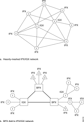
Integrating a Cisco BPX 8600 series broadband backbone with its higher speed trunking and switching capacity expands the network capacity with minimal disruption of the existing network. The Cisco BPX 8600 series broadband switch provides expansion capabilities with full compatibility with the Cisco IGX 8400 series multiband switch and the Cisco IPX narrowband switch. The Cisco BPX 8600 series broadband switch also utilizes the same network management platform as the Cisco IGX 8400 series multiband switch and the Cisco IPX narrowband switch.
The actual bandwidth used on the trunks between a Cisco BPX 8600 series broadband switch and an Cisco IGX 8400 series multiband switch or Cisco IPX narrowband switch may be incrementally increased in T1 or E1 size steps. Therefore, existing Cisco IGX 8400 series multiband T1 and E1 trunks can be decommissioned one at a time and their cell traffic routed across the new Cisco BPX 8600 series broadband network backbone. The ATM interface to the Cisco IGX 8410 multiband switch economically serves small feeder locations and provides all of the same interfaces as the larger Cisco IGX 8420 or 8430 multiband switches.
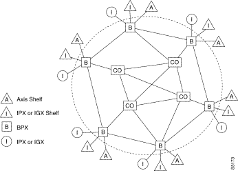
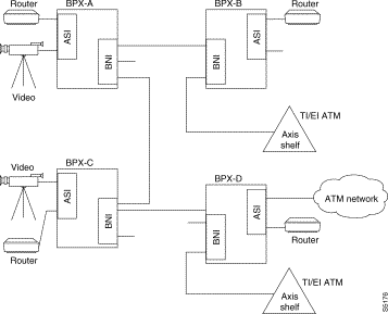
ATM can be used to economically provision a variety of services including frame relay, SMDS, compressed voice, on-demand video, and circuit emulation services. Cisco BPX 8600 series broadband switches can serve as ATM service nodes for large central office digital switches in public switched networks (Figure 5-4). This allows the public service providers to offer ATM service to users who are not so concentrated as to justify the installation of a large ATM central office switch.
As ATM service nodes, Cisco BPX 8600 series broadband switches with Cisco MGX 8220 edge concentrator shelves, Cisco IGX 8400 series multiband switches and Cisco IPX narrowband switches configured as shelves, as well as Cisco IGX 8400 series multiband switches and Cisco IPX narrowband switches, provide ATM access and termination closer to the user and transport ATM cells to central office ATM platforms. Each Cisco BPX 8600 series broadband switch acts as a concentrator for the narrowband inputs from a number of local user devices. The Cisco IGX 8400 series multiband switch, the Cisco IPX narrowband switch, and the Cisco MGX 8220 edge concentrator convert these inputs to cells that are forwarded to the Cisco BPX 8600 series broadband switches over T3 or E3 trunks. Local connections can be switched back to the outer layer of Cisco IGX 8400 series multiband switches and Cisco IPX narrowband switches, and longer-distance connections can be switched to the public network at a suitably equipped central office.
Frame relay, linking LANs over wide areas, is a rapidly-growing offering of both public switched and private networks. Current user devices (routers, hubs, bridges, etc.) typically operate at rates of 56 or 64 Kbps and below on the network side. As the size of LANs grow and the operating rates of personal computers and workstations increase, new generations of LAN hubs, routers, etc. will operate at T1/E1 data rates and above offering many high-speed PVCs over a single port. The network bandwidth must also grow accordingly to provide the level of service initially provided.
It is envisioned that data networks will evolve to configurations employing a narrowband ATM shell ringing a broadband ATM core backbone network as illustrated in . The narrowband shell, consisting primarily of Cisco IPX narrowband tributaries, Cisco IGX 8400 series multiband switches and Cisco IPX narrowband switches configured as shelves, and Cisco IGX 8400 series multiband switches configured as routing hubs will serve areas of low but increasing user density. This network configuration pushes the frame relay interface closer to the customer to reduce long-haul charges consolidating user data using the more economical hardware of Cisco IGX 8400 series multiband switches and Cisco IPX narrowband switches.
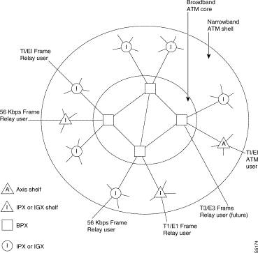
For frame relay connections terminating at more remote destinations, the Cisco IGX 8400 series multiband switches and Cisco IPX narrowband switches would feed this traffic to the higher-speed broadband core network utilizing the very high-speed tandem switching characteristic of the Cisco BPX 8600 series broadband switches. These PVCs would likely traverse many hops. The higher speed of the broadband core network would offer reduced overall delay and increased trunk bandwidth avoiding the gridlock that could occur if this backbone traffic were routed over the narrowband shell.
For connections terminating at other local or intermediate destinations, the Cisco IGX 8400 series multiband switches can communicate with adjacent Cisco IGX 8400 series multiband switches using short-haul T1 or E1 facilities. Typical hop counts of 1 or 2 hops would be the norm for these connections.
To ease the transition from existing frame relay networks to networks based on ATM, Cisco offers a wide range of LAN interconnect interfaces from low-speed frame relay e.g., 56 or 64 Kbps or less, T1/E1 interfaces with multiple virtual ports, to direct ATM data interfaces operating at DS1, E1, DS3, and E3 rates. The UFM cards on the Cisco IGX 8400 series multiband switch support frame relay T1/E1, HSSI, X.21, and V.35 interfaces.
A 6.312 Mbps T2 digital trunk interface is available from Cisco. This is for markets where 6 Mbps trunks are more prevalent than T3 trunks (e.g., the Japanese markets). T2 trunks provide four times the bandwidth as T1 trunks. Since the Cisco IGX 8400 series multiband, Cisco IPX narrowband, or Cisco BPX 8600 series broadband network interface is either T3 or E3, a rate adapter is required.
This function is provided by Cisco with the AT3-6M Interface Adapter. One unit is required at each node to be connected to the T2 network (see ). The nodes are software configured to restrict the bandwidth allocation on these trunks to avoid overloading the interface adapters and associated trunk.

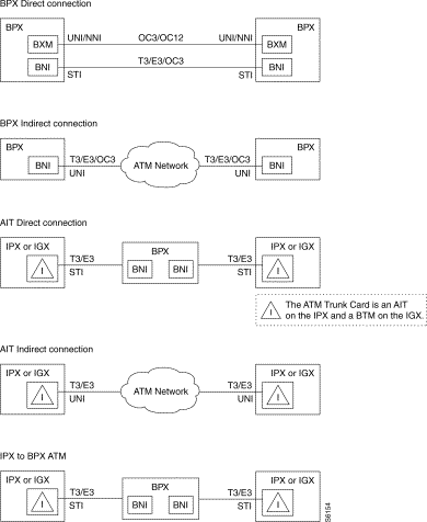
Using the standardized UNI header allows the Cisco IGX 8400 series multiband switch, the Cisco IPX narrowband switch, or the Cisco BPX 8600 series broadband switch to be used in a generic ATM network (cloud) with a mix of various equipment. With the use of BXM cards in trunk mode, Cisco BPX 8600 series broadband switches can be connected using the standard NNI header. When using BNI cards, to take advantage of several features unique to Cisco WAN switching equipment, including ForeSight dynamic closed loop feedback congestion control, the STI header type, an extension of the standard UNI header, must be used. These five connection types are illustrated in Figure 5-7.
These are the five types of ATM network connections supported:
The Cisco BPX 8600 series broadband/Cisco IGX 8400 series multiband ATM networks have a flexible architecture and configuration interface that allows the user to define service parameters to tailor their connection types, including CBR, VBR, ABR, and UBR. Up to 32 different classes of service can be predefined for various connection types.
ATM connections are identified by a two-part address field consisting of a Virtual Path Identifier (VPI) and a Virtual Circuit Identifier (VCI) similar to the manner in which frame relay connections are identified.
ATM connections can be provisioned to support different service requirements. Currently, these include:
ATM service (connections) can be provisioned directly on a Cisco WAN switching ATM network through the use of a BXM T3/E3, 155, or 622 card configured for port mode (service access, UNI), or of an ASI-1 or ASI-155 card. The ATM Service Interfaces provides direct connection of high-speed user devices (such as routers or hubs) with ATM standard interfaces to Cisco WAN switching ATM wide-area networks. The BXM cards support ATM Traffic Management 4.0 VSVD congestion flow control for ABR connections.
Each ASI-1 card set, installed in the Cisco BPX 8600 series broadband switch, provides two T3 or DS3 ATM service interfaces (ports), and each ASI-155 card set provides two OC3/STM-1 ATM service interfaces (ports). BXM T3/E3 card sets are available with either 8 or 12 service interfaces, BXM-155 card sets are available with either 4 or 8 ports with MMF, SMF, or SMFLR interfaces. BXM-622 card sets are available with either 1 or 2 ports with SMF or SMLR interfaces.
The ports on the BXM or ASI cards can be configured as a User-to-Network (UNI) interface for directly interfacing user ATM devices to the ATM network as shown in . Or the ports may be configured as a Network-to-Network Interface for interface between two dissimilar ATM networks (Figure 5-8).
The Cisco MGX 8220 edge concentrator shelf provides an interface to the Cisco BPX 8600 series broadband switch for T1/E1 frame relay, T1/E1 ATM, CES, and FUNI connections. With interworking, the frame relay connections may be terminated at another Cisco MGX 8220 edge concentrator, an ASI on a Cisco BPX 8600 series broadband switch, a Cisco IGX 8400 series multiband switch, or a Cisco IPX narrowband switch. The Cisco MGX 8220 edge concentrator shelf T1/E1 ATM connections may be routed to another Cisco MGX 8220 edge concentrator or to a BXM or an ASI on a Cisco BPX 8600 series broadband switch.
The Cisco IGX 8400 series multiband switch and the Cisco IPX narrowband switch provide bandwidth management capabilities for narrowband networks to:
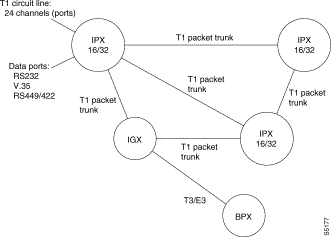
A simplified example of a Cisco IPX 16/32 narrowband T1 network is shown in Figure 5-9. The various node, consisting of Cisco IPX 16/32 narrowband T1 network switching bandwidth managers, are interconnected with T1 packet trunks that carry packets of data at 1.544 Mbps. The data input to the network may consist of a mixture of voice transmission from D4 channel banks or digital PABXs, various low-speed point-to-point data circuits, or frame relay data. The following network interfaces are supported by the Cisco IGX 8400 series multiband switch and the Cisco IPX narrowband switch:
Comment: | In the following, the FRM, HDM, and CVM cards perform the same functions in the Cisco IGX 8400 series multiband switch as the FRP, SDI, and CDP do in the Cisco IPX narrowband switch. |
The T1 packet trunks contain the standard framing bit for channel synchronization but the remaining T1 frame data is not channelized. Nodes connect to other nodes using a minimum of one packet trunk and in larger networks often interconnect in ring or star configurations to provide alternate routing paths for maximum protection against outages that may result from a failed T1 line.
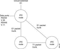
A simplified example of a Cisco IGX 8400 series multiband E1 network is shown in Figure 5-10. Each Cisco IGX 8400 series multiband switch is connected to the user's PBXs and channel banks via E1 circuit-switched lines. Data connections are made via various data port interface types. The following network interfaces are supported by Cisco IGX 8400 series multiband and Cisco IPX narrowband E1:
Comment: | In the following, the FRM, HDM, and CVM cards perform the same functions in the Cisco IGX 8400 series multiband switch as the FRP, SDI, and CDP do in the Cisco IPX narrowband switch. |
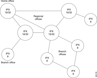
The eight slot Cisco IPX narrowband switch operates seamlessly in existing and new networks with Cisco's existing family of cell relay switches. It also provides both T1 and E1 packet line and circuit line interfaces for use in international networking. The eight slot Cisco IPX narrowband switch can be used in large networks where there is a mixture of eight slot Cisco IPX narrowband switches, sixteen slot Cisco IPX narrowband switches, sixteen slot Cisco IPX narrowband switches and Cisco IGX 8400 series multiband switches (). It can be used as a feeder () to a larger node, or it can be configured as a Cisco IPX narrowband switch shelf and connected to a Cisco BPX 8600 series broadband switch, as can a Cisco IGX 8400 series multiband switch. Or, it can be used in small networks by itself. Typical applications include:

The BC-J1 and BC-Y1 back cards provide Cisco IGX 8400 series multiband switches and Cisco IPX narrowband switches with the capability to interface to J1 circuit lines and Y1 network trunks in Japan. Y1 trunks are used in Japan and are similar to T1 trunks described earlier except they use a Coded Mark Inversion (CMI) line code instead of Alternate Mark Inversion used by the T1 lines. This assures a line signal with sufficient one's density for the line repeaters.
Likewise, the J1 circuit line resembles a channelized E1 circuit line except that it runs at the
1.544 Mbps. T1 rate and also uses the CMI line code. The BC-J1 back card is used in combination with a CVM on a Cisco IGX 8400 series multiband switch (CDP in the Cisco IPX narrowband switch) front card to provide an interface for a circuit line to a PBX using a Japanese standard TTC-JJ-20, 2.048 Mbps circuit (J1 circuit). In all other aspects, these networks are similar to the T1 and E1 networks just described.
Frame relay networks have grown rapidly in popularity for their ability to provide full mesh connectivity for LAN-to-LAN interconnections. Instead of transferring bits between fixed locations like a normal synchronous data circuit, a frame relay data circuit acts like a wide area LAN (WAN). A sending device places an addressed frame into the network and it arrives at its destination.
To be totally effective, every LAN should have one or more connections to every other LAN. To do this with dedicated circuits, can require a large number of physical circuits for networks with more than a just a few locations. For example, illustrates a network interconnecting seven LANs. This will require 21 circuits for full mesh connectivity. In general, a network interconnecting "n" LANs will require n(n-1)/2 circuits for full mesh connectivity.
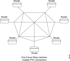
Cisco WAN switching frame relay networks utilize Permanent Virtual Circuits (PVCs) to carry frames of user data. With a PVC instead of a dedicated circuit, the user perceives a connection that is permanently in-place but one that doesn't utilize any network bandwidth until there is actually data to be transmitted. Frame relay PVCs are routed through the network over packet or ATM trunks using either NTC or AIT cards in the IPX.
Frame relay ports are added to the Cisco IPX narrowband switch using a Frame Relay PAD (FRP) front card and associated Frame Relay Interface (FRI) back card or to the Cisco IGX 8400 series multiband switch using the Frame Relay Module (FRM) and FRI back card.
Frame relay ports are added to Cisco IGX 8400 series multiband switches using FRM, UFM-C, or UFM-U front cards and a variety of T1/E1, HSSI, X.21, and V.35 back cards, as applicable.
On the Cisco MGX 8220 edge concentrator, the frame relay interface is provided by the FRSM card. The Cisco IGX 8400 series multiband and the Cisco IPX narrowband card sets provide four or more UNI ports for interface to frame relay routers, hubs, or bridges as indicated in the following:
In the Cisco IGX 8400 series multiband switch or the Cisco IPX narrowband switch, each frame relay card can carry up to 252 PVCs. Each node can accommodate up to 1024 PVCs, which would require up to four frame relay card sets (FRM or FRP/FRI) to achieve maximum capacity.
The Port Concentrator provides up to 44 low-cost frame relay ports and connects to the Cisco IPX narrowband switch via an FRP-2 card or to the Cisco IGX 8400 series multiband switch via an FRM-2 card. Connection management using the Port Concentrator ports is the same as that for frame relay connections to the FRP and FRM cards.
There are two types of network interfaces protocols that are supported by Cisco WAN switching frame relay ports:
Figure 5-14 illustrates these two frame relay interfaces. The User-to-Network Interface is defined as the port where a user device, such as a router, interfaces with a Cisco WAN switching wide area network carrying the frame relay traffic. Currently, the Cisco IGX 8400 series multiband switch and the Cisco IPX narrowband switch support UNI via the following protocols: ITU-T Q.933 Annex A, ANSI T1.617 Annex D and StrataCom LMI, which offers additional features over the other protocols. Refer to the Cisco MGX 8220 Installation and Configuration and Cisco MGX 8220 Command Reference publications and the FastPAD Reference publication for further information on the protocols they support.
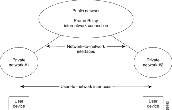
A Network-to-Network Interface is a port that forms a boundary between two independent wide area networks, e.g. a Cisco WAN switching network and another network and may or may not consist of Cisco WAN switching equipment. No user device is connected, only another network port.
 |
Note ELMI is an enhancement to LMI. ELMI adds capabilities that are not currently supported in LMI so that network switches, e.g., Cisco BPX 8600 series broadband switches, Cisco IGX 8400 series multiband switches, etc., can inform a user (routers, bridges, etc.) about network parameters such as various quality of service (QoS) parameters. Depending on the implementation, these might be such parameters as Committed Information Rate (CIR), Committed Burst Size (Bc), Excess Burst Size (Be), maximum Frame Size, etc. |
LMI transmits on a logical connection between the Cisco IGX 8400 series multiband switch and the Cisco IPX narrowband switch and the user device (router) separate from the data path using DLCI 1023. This connection is a special PVC, carrying messages between the Cisco IGX 8400 series multiband switch or the Cisco IPX narrowband switch and the user device. The messages transmitted via the LMI protocol provide the following information to the user device:
Some user devices can obtain the network configuration dynamically using LMI messages. With these devices, the Network Administrator assigns Data Link Connection Identifiers (DLCIs) for both ends of each connection in the network and the user device interrogates the frame relay port to determine the DLCI assignment. If the user device does not have this feature, then the Network Administrator must manually configure the user device to use the DLCIs programmed into the Cisco IGX 8400 series multiband/Cisco IPX narrowband network.
Currently, Cisco IGX 8400 series multiband and the Cisco IPX narrowband frame relay ports report the status, active or failed, of each frame relay connection within the network to the user devices at both ends of the circuit. The status is reported using the frame relay User-Network Interface (UNI) protocol and consists of the status of the far end user device as well as any failure or congestion on the overall connection.
When a circuit spans multiple networks, it is desirable to maintain this status reporting for the entire length of the PVC. This necessitates obtaining the circuit status from the foreign network and including it with the status reported by the local network. The frame relay Network-to-Network Interface (NNI) feature is used when extending connections between a Cisco WAN switching frame relay network and another independent, Cisco WAN switching or a non-Cisco WAN switching frame relay network.
At each port where one network connects to another network, Frame Relay NNI passes the circuit status for internetwork connections between the two networks. NNI status messages indicate not only the status of the remote user device, but also the combined status of each network link traversed by the multi-network PVC.
Within a Cisco WAN switching network, the status of every frame relay PVC is known by every node in the network since it is distributed network-wide by system software communicating with each node. The status of each PVC is sent to the user device over the UNI as discussed in the first paragraph of this section. There are three possible status to report:
However, there may be PVCs that extend beyond the boundaries of a Cisco WAN switching network and connect to a user in a totally separate network. The frame relay Network-to-Network Interface (NNI) is used to forward the connection status through to the User-to-Network Interface (UNI) ports within the different networks. A frame relay port is defined as a UNI or an NNI port with software configuration. In order for this feature to be completely implemented, the interconnected ports in both networks must support NNI.
The frame relay port uses a number, the Data Link Connection Identifier (DLCI), to identify each bidirectional frame relay connection at the local interface between the user device and the frame relay network. This number is assigned by the network operator when the connection is added to the network.
An example is shown in . In this illustration, there are three possible destinations for this data frame, A, B, or C, and each needs a unique DLCI to identify the PVC to these destinations.

Note that the DLCI has only a local significance. The frame relay port and the user equipment (router) need to coordinate the use of DLCIs but the DLCI does not matter to anything else in the network. Consequently, DLCI numbers only have to be unique at each frame relay port to the network. The same numbers may be reused at other ports in the network although this numbering scheme may be somewhat more difficult to administer.
Each FastPAD provides up to eight analog voice telephone circuits and up to six data ports. It supports direct interface to telephone with both pulse or tone dialing and a variable rate voice compression for efficient bandwidth utilization. Customer data rates supported range from 2.4 to 19.2 Kbps synchronous or asynchronous for five of the data channels to 64 Kbps synchronous for the sixth channel.
The FastPAD takes the various frame relay, voice, and data inputs and multiplexes them into frames for transmission over a composite link. The resulting frames are encapsulated in a standard frame relay format header with a unique Data Link Connection Identifier (DLCI) assigned to each FastPAD. These frames are then applied to any standard frame relay network for forwarding to another FastPAD at the destination. DLCI bundling of multiple logical connections within single PVCs reduces the number of PVCs required within the network. With a FastPAD network in place, a user automatically has the advantage of a private telephone network without the expense of providing a PBX or key system at each site.
Each FastPAD is assigned a unique dialing code in the network when it is initially configured. Thus, in small site applications, where there are no PABXs, telephones can be directly connected and the network will provide the call switching between sites equipped with FastPADs.
Similarly, a FastPAD network provides a cost-effective way of linking a number of small LANs, some of which may consist of only one or two terminals, without having to purchase a separate router at each location. The FastPAD acts very much like a router itself.
The FastPAD Access Multiplexer provides an economical access device for sites where only a few of voice and data circuits are required but where it is desired to gain access to a network that perhaps links many widely separated locations. Since the composite link of the FastPAD is directly compatible with the FRP/FRI interface of the Cisco IPX narrowband switch, or the FRM/FRI interface of the Cisco IGX 8400 series multiband switch, Permanent Virtual Circuits (PVCs) can be established between Cisco IGX 8400 series multiband switches or the Cisco IPX narrowband switches to connect many FastPADs using a frame relay network.
An example of a simple network using FastPADs across a Cisco IGX 8400 series multiband or a Cisco IPX narrowband frame relay network is illustrated in . This might serve to link a corporate headquarters in Zurich where a host computer and MIS database is located with two field offices, one in London and the other in New York. The field offices require several phone connections and several low-speed database access circuits. Speed dialing between the various offices is a plus.
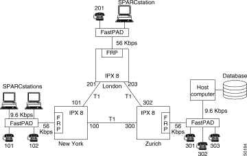
In the example of , the FastPAD voice slots have been assigned dialing codes of 101 and 102. At London, the dialing code is 201, and in Zurich they are 301, 302 and 303. If New York wants to call London, they can just dial 201. The FastPAD keeps an internal routing table of all the dialing codes and destinations.
Since each port attached to the FastPAD has two destinations to reach, it requires two DLCIs. At New York, an arbitrary DLCI of 100 is used to route the PVC to Zurich while 101 routes a second PVC to London. The DLCIs are in reality assigned indirectly by the FastPAD when the user assigns a node number and slot number to each unit.
Since the FastPAD connects to the Cisco IGX 8400 series multiband switch via an FRM, the FastPAD is considered to be a frame relay user device attached to a frame relay network device. When linking a FastPAD to a Cisco IGX 8400 series multiband switch, the FastPAD should be equipped with V.35 interface cards/cables and the frame relay port should use the FRI-V35 backcard. The link speeds supported between the FastPAD and the Cisco IGX 8400 series multiband frame relay port include 56, 64, 112 or 128 Kbps. Refer to the FastPAD User's Guide for additional configuration information.
Cisco WAN switching cell-relay networks can easily be configured to provide direct communication links between domestic and international locations each using the differing transmission standards, e.g., T1 and CEPT E1.
For example, in , the Cisco IPX narrowband network is used to extend voice and data circuits in a T1 network with a node in Washington D.C. to connect via satellite T1 or E1 packet trunks to a node in London, England serving a separate CEPT E1 network. Not only is the bit rate (and the frame format) of the two networks different, but the VF encoding law, signalling formats, and signalling conditioning requirements are different.
Comment: | In the following, the FRM, HDM, and CVM cards perform the same functions in the Cisco IGX 8400 series multiband switch as the FRP, SDI, and CDP do in the Cisco IPX narrowband switch. |
Building a seamless international network has always been facilitated by a cell relay network but the introduction of the CDP card makes protocol conversion even easier than before. All of the voice and signalling parameters indicated in can be programmed by the network operator within each CDP.
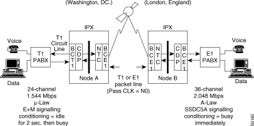
In this example, the CDP at node A, terminates the T1 circuit line to the PABX in Washington with a corresponding BC-T1 back card. It is programmed for the voice parameters required by the Washington PABX in the transmit direction and for the parameters required by the London PABX in the receive direction. The CDP in Node A makes the appropriate conversions, adds gain or loss as required for level adjustment, packetizes the channels (up to 24), and sends them to the NTC, with its attendant back card (E1 in this example but could be T1 depending on the satellite circuits used).
In London, the Node B NTC and associated BC-E1 terminates the E1 line, receives the packets, and forwards those packets with the proper destination header to the CDP connected to the E1 PABX as shown. The Node B CDP is programmed for the requirements of the London PABX with no conversion (all the conversion was performed in Node A in Washington). This CDP assembles 30-channel E1 frames from the packet data received, and when a frame is full, sends it out to the PABX.
Note, the packet trunk connecting nodes A and B has to be either E1 or T1 with the same back card at each NTC. However, the two circuit lines connecting the PABXs can be T1 at one end of the circuit and E1 at the other. A distinct requirement is that the total number of DS0 channels assigned on this virtual circuit be the same at both ends. If 24 circuits are assigned, based on the T1 out of the Washington PABX, then the London PABX will have six channels that can be assigned to other circuits (30 E1 - 24 T1 = 6).
These two nodes will usually be part of two separate networks as far as clocking is concerned, each operating at their geographic area's basic network rate (1.544 Mbps in the US network and 2.048 Mbps in the UK network). Since the packet trunk connecting Node A and Node B is over satellite it is not permitted to pass clock. Therefore, the two networks will be isolated from each other as far as network timing, an example of pleisiochronous networks (discussed more fully in Example of a Pleisiochronous Network). the Cisco IPX narrowband and Cisco IGX 8400 series multiband switches operate with no loss of data in pleisiochronous networks using frame slips during idle frames to accommodate the differences in the two network clocks.
Comment: | In the following, the FRM, HDM, and CVM cards perform the same functions in the Cisco IGX 8400 series multiband switch as the FRP, SDI, and CDP do in the Cisco IPX narrowband switch. |
The Cisco IPX Channelized Data Pad (CDP) card provides communication between T1 and CEPT (E1) connections. This card provides data rates of from 512 Kbps to 2.4 Kbps. These connections can terminate with standard RS-232, RS-449, V.35 interfaces. This card also provides echo cancellation and compression of 8:1 per channel with 16 Kbps ADPCM and 2:1 Voice Activity Detection.
IPX transition functionality is provided by the CDP on both the CEPT (E1) IPX node and the T1 node. This function allows a voice port on a channel bank or PBX in T1 to connect to a voice port on a channel bank or PBX on the CEPT (E1), and assumes a connection is required by a voice protocol in a CEPT (E1) system that is A-law encoded and a voice port in the T1 system that is µ-law encoded.
A T1 system obtains ADPCM voice connections on the CDP card. Signalling conversion is provided between 4W E&M and SSDC5A (British signalling convention).
 |
Note This function does not support rotary dialing, V.25 modem connections, or 64 Kbps voice. |
Voice communication paths require that the PCM samples sent between the T1 and E1 Cisco IPX narrowband nodes be converted from µ-law to A-law. In order for this conversion to take place, a CDP must be installed in the T1 Cisco IPX narrowband node, and a CDP must also be installed in the CEPT Cisco IPX narrowband node.
The Configure Line (cnfln) command includes parameters such as line coding (HDB3 or AMI, encoding type (µ-law or A-law), and clocking type (loop clock or not) that can be programmed on individual or groups of channels. Since the circuit line at each end of an international hop is separate, the parameters are programmed separately and do not have to be the same. The IPX and IGX make the conversion automatically.
The Configure Interface Type for Voice Channel (cnfvchtyp) command is used to set the channel parameters for the CDP (in IPX) or CVM (in IGX) used in an international (or any other node). There are currently 23 standard channel or trunk interface types already defined (for example 2WE&M & 4WE&M, FX, DP, DX, RD, R1 & R2). These channel definitions are used primarily to define what to do with various VF circuit parameters during circuit failure.
Each type has preset A and B signalling conditioning values as well as the substitute PCM voice sample sent to the attached equipment (often an idle code) in case the connection fails. If none of the predefined conditions fits the needs of the international node, the user can specify the signalling conditioning and voice code to be transmitted by using a template.
The Configure Transmit Signalling (cnfxmtsig) command allows the user to pass, block, or convert any or all of the A, B, C and D signalling bits in the transmit direction. A similar command is available for Receive Signalling. The Configure Channel Gain (cnfchgn) command specifies the loss or gain (-8 dB to +6 dB) to add to the channel to set the end-to-end transmission levels for each voice circuit. There are similar commands for configuring and converting various data channel signalling lead and alarm output patterns.
Fortunately, because the nodes resynchronize by dropping idle cells/packets, there usually is no loss of user data. But if there are few idle cells/packets, as on a fully utilized trunk, the resynchronizing may have to drop cells/packets containing valid data just to remain in frame.
Another problem that occurs when the data rate on the incoming trunk does not match the node timing, is that the packet buffers will eventually overflow or underflow. This results in either lost data or underutilization of the buffer. Network-wide clock synchronization eliminates these problems.
Each node in the network has available to it four sources of timing:
To obtain clock from a Common Carrier, the packet trunks defined as clock sources must pass through a Digital Access and Crossconnect System (DACS) or similar device that retimes the data stream. A trunk must be activated and clear of alarms before it can be used as a network clock source. In addition, a packet trunk must be configured not to pass clock before it can be defined as a clock source. Each source of clock for a node is ranked according to its source stability as follows:
These sources are defined in the node database using the Configure Clock Source (cnfclksrc) command. They can be displayed at any time using the Display Clock Sources (dspclksrc) command. Once defined, the location and type of the network clock source is broadcast to all nodes in the network. Each node maintains a list of all available clock sources for the network. This list is preserved during a power failure or controller card switch on the node.
Cisco WAN switching cell relay networks use a fault-tolerant network synchronization scheme similar to that used by telcom digital switching offices. The node clocking scheme ensures that all nodes in the network are automatically synchronized to the nearest, highest level clock available. This synchronization remains in effect even after line failures, line repairs, joining of sub networks and all other network topology changes. Each node selects the clock source in the following hierarchy:
1. If a clocking hierarchy is defined, it automatically selects the nearest working, primary source if it is available.
2. Where there are two packet or circuit line sources to choose from, it selects the lower numbered line to use.
3. If a primary source is unavailable, it selects the nearest secondary source.
4. If a secondary source is unavailable, it selects the nearest tertiary source.
5. If none of the defined sources are available, as may be the case in a catastrophic network failure, the Cisco IGX 8400 series multiband switch, the Cisco IPX narrowband switch, or the Cisco BPX 8600 series broadband switch reverts to its internal oscillator.
6. If no clocking hierarchy is defined in the network, the Cisco IGX 8400 series multiband switch arbitrarily selects the internal clock from one of the nodes as the active network source.
The clock source selected is monitored by internal circuits in the node. If it is lost or if it drifts out of range, it is marked as failed and the node controller looks for another source. The node's active clock source and the path to that clock source can be displayed by the operator using the Display Current Clock (dspcurclk) command.
A network's clock source and line characteristics are configured as part of the node installation process. Thereafter, clock sources would be redefined when networks are reconfigured or line status is changed. Engineering considerations by which to assess and define clock sources include:
Trunks may be classmarked as being able to pass clock or not, or to loop clock or not, using the Configure Trunk (cnftrk) command. A trunk passes clock if the clocking transmitted at one end is recovered at the receive end and may be used to clock the node. If a trunk or circuit line comes from a source that should be isolated from the network, specifying looped clock allows the data to be clocked into and out of the CDP or NTC using this timing source but it does not propagate through the node and into the network. The difference is that the node clock is not retransmitted down the trunk or circuit line.
Circuit lines can also be defined as clock sources in the same manner as trunks. If a small network consists of a star of several circuit line routes and one of them is a master at a headquarters site, for example, its clock source can be used to synchronize the network and possibly all the other routers permitting them to pass data in the most efficient manner between themselves.
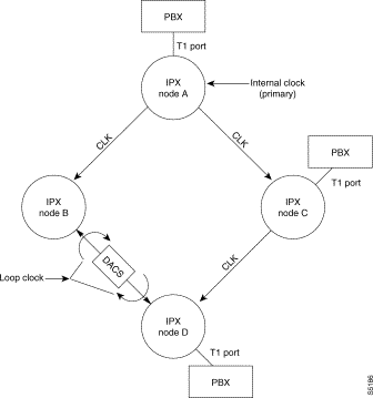
illustrates a typical network clock architecture. The primary source is the internal oscillator in IPX Node A. The clock propagates to Nodes B and C over trunks A-B and A-C, which should be defined as passing clock (default). It is propagated to Node D over trunk C-D only.
In this example, a digital central office (DCO) using a DACS is located in the trunk B-D hop and this source of timing is to be isolated from the IPX network. To do this trunk B-D is marked to loop clock. The timing from the DCO is used only to time the data on trunk B-D and is kept out of the network. As an alternative, the IPX network could be set to clock off the DACS. In this case, the trunks between node B and node D would be set to pass clock.
The PABXs off Nodes A, B and C are, for this example, all digital PABXs with direct T1 interfaces. These should all be set up for loop timing so they will be synchronous with the network. Their associated circuit lines should be marked as not passing clock unless one or more of the PABXs are used for the secondary or tertiary source of timing for this network.
The Common Carriers each have their own master clocks and, to date, they are not synchronized to each other. For this reason, it is best to avoid, if possible, mixing packet trunks from different carriers. If this is unavoidable, consider using the CDP or NTC cards. These cards can turn clock around back towards the intervening digital central office(s) to isolate the undesirable timing source.
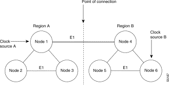
Figure 5-19 shows an example of a network that may operate as a pleisiochronous IPX network. Nodes 1, 2, and 3 are in Region A while nodes 4, 5, and 6 are in a separate Region B. Each region A has a node whose internal clock is used as a primary clock source. If the E1 packet trunk connecting node 1 to node 4 is defined as not passing clock, the two regions will be synchronous unto themselves but not to each other. This is called pleisiochronous operation. With this configuration, the E1 frames on the node 1 to node 4 packet trunk may need to be slipped occasionally to account for the two independent network clocks.
![]()
![]()
![]()
![]()
![]()
![]()
![]()
![]()
Posted: Tue Jan 16 11:14:21 PST 2001
All contents are Copyright © 1992--2001 Cisco Systems, Inc. All rights reserved.
Important Notices and Privacy Statement.