|
|

This chapter is provided for users who wish to have an in-depth knowledge of the ATM and broadband trunks functions. It discusses ATM concepts and the various high-speed digital trunks that are used to carry ATM connections.
This chapter containts the following:
Asynchronous Transfer Mode (ATM) uses a very flexible method of carrying broadband information between devices on a local or wide area network. It transmits this information using small, fixed length (53-byte) data packets, called cells, over high-speed digital transmission facilities. A key advantage to ATM is that it has been designed to carry voice, video, and data equally well on a single network.
ATM was developed to provide large amounts of bandwidth for network connections economically and on demand. When a user does not need access to a network connection, the bandwidth is available for use by another connection that does require it. ATM allows the bandwidth to be easily scaled to the requirements of the individual user.
ATM provides a distinct separation between the preparation of the customer data and the transportation of the data over the network. This allows a network operator to migrate to ATM using only the amount of bandwidth initially required. As bandwidth requirements increase, the user can scale up by using higher speed data links.
ATM is an outgrowth of Broadband Integrated Services Digital Network (B-ISDN), which in itself is an extension of ISDN that provides a definition for services and interfaces for public telecommunications networks.
B-ISDN utilizes a layered architecture similar to the Open Systems Interconnection (OSI) 7-layer model. ATM redefines the lower three layers as indicated in Figure 8-1. These layers, the Physical Layer, ATM Layer, and ATM Adaptation Layer will be described in detail in the following paragraphs. By bypassing the OSI network layer, ATM is able to process cells much more quickly and efficiently than current packet-based routing. The higher-order four layers are associated with specific user applications served by the ATM layers.
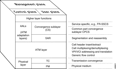
Physical Layer
Initially, ATM will utilize existing physical transport media like the North American DS3 and CEPT E3 facilities and may be carried on T1 and E1 for users with low initial bandwidth requirements. For higher bandwidth requirements, the Synchronous Optical Network (SONET) provides a well defined and well accepted set of data rates (see Table 8-1). For example, the BPX provides 45 Mbps T3, 34 Mbps E3, and 155 MbpS interfaces but is designed to be easily expanded to include up to OC-12 port interfaces.
There are two sub-layers to the Physical Layer that separate the physical transmission medium and the extraction of data:
The Physical Medium Dependent concerns itself with the details specific to a particular physical layer, transmission rate, physical connector type, clock extraction, etc. For example, the SONET data rate utilized is part of the PMD. Transmission Convergence is involved with extracting the information content from the physical layer data transmission. This includes HEC generation and checking, extracting cells from the incoming bit stream, and processing of idle cells.
| DataRate | OCLevel | SONETDesignation | ITU-TDesignation |
|---|---|---|---|
52 Mbps | OC-1 | STS-1 |
|
155 Mbps | OC-3 | STS-3 | STM-1 |
466 Mbps | OC-9 | STS-9 | STM-3 |
622 Mbps | OC-12 | STS-12 | STM-4 |
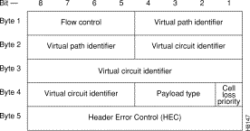
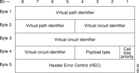
The ATM layer processes ATM cells. The format of the ATM cell consists of a 5-byte header and a 48-byte payload (Figure 8-2). The header contains the ATM cell address and other important information. The payload contains the user data being transported over the network. Cells are transmitted serially and propagate in strict numeric sequence throughout the network.

The most important fields in all three ATM cell header types are the Virtual Path Identifier (VPI) and a Virtual Circuit Identifier (VCI). The VPI identifies the route (path) to be taken by the ATM cell while the VCI identifies the circuit or connection number on that path. The VPI and VCI are translated at each ATM switch, they are unique only for a given physical link.
A 4-bit Generic Flow Control (GFC) field in the UNI header is intended to be used for controlling user access and flow control. At present, it is not defined by the standards committees and is generally set to all zeros.
A 3-bit Payload Type Indicator (PTI) field indicates the type of data being carried in the payload. The first bit is a "0" if the payload contains user information and is a "1" if it carries connection management information. The second bit indicates if the cell experienced congestion over a path. If the payload is user information, the third bit indicates if the information is from Customer Premises Equipment.
In the STI header (Figure 8-5), these bits are used to indicate data from certain BPX queues corresponding to various classes of service e.g. OptiClass, the enhanced class of service feature of the BPX.
The Cell Loss Priority (CLP) bit follows the PTI bits in all header types. When set, it indicates this cell is subject to discard if congestion is encountered in the network. For frame relay connections, the frame Discard Eligibility is carried by the CLP bit. The CLP bit is also set at the ingress to the network for all cells carrying user data transmitted above the minimum rate guaranteed to the user.
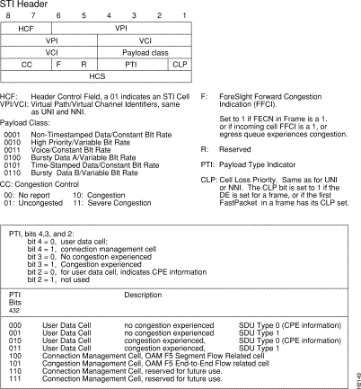
Some of the VCI bits have been reserved in the STI header type to implement ForeSight congestion management control, unique to StrataCom networks, refer to Figure 8-5 and Table 8-2.
| Function | Possible Status |
|---|---|
Congestion Control | No report |
| Uncongested |
| Congestion |
| Severe Congestion |
Forward Congestion Indicator | No ForeSight congestion indication. |
| Congestion indication in incoming cell or congestion detected locally. |
Reserved | Not used. |
To assure reliable delivery of each ATM cell, a Header Error Correction (HEC) checksum field is included as the last field of the header. This is an 8-bit result of a CRC check on the header bits (the payload bits are not checked). The HEC is calculated and inserted after all other fields in the header have been inserted. When ATM cells are carried on unframed digital facilities, the HEC is used for cell delineation.
Each ATM cell contains a two-part address, VPI/VCI, in the cell header. This address uniquely identifies an individual ATM virtual connection on a physical interface. Virtual Channel Indicator (VCI) bits are used to identify the individual circuit or connection. Multiple virtual circuits that traverse the same physical layer connection between nodes are grouped together in a virtual path (Figure 8-6). The virtual path address is given by the Virtual Path Indicator (VPI) bits. The Virtual Path can be viewed as a trunk that carries multiple circuits all routed the same between switches.
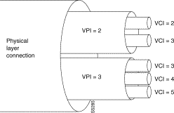
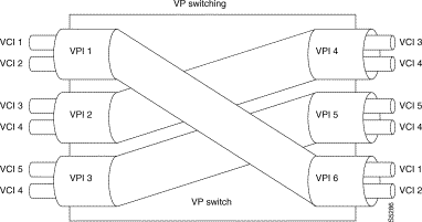
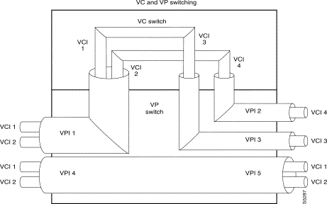
The VPI and VCI addresses may be translated at each ATM switch in the network connection route. They are unique only for a given physical link. Therefore, they may be reused in other parts of the network as long as care is taken to avoid conflicts. Figure 8-7 illustrates switching using VP only, which may be done at tandem switches while Figure 8-8 illustrates switching on VC as well as VP.
The VCI field is 16 bits wide with UNI and NNI header types described earlier. This allows for a total possible 65, 535 unique circuit numbers. The UNI header reserves 8 bits for VPI (256 unique paths) while the NNI reserves 12 bits (4,096 unique paths) as it is likely that more virtual paths will be routed between networks than between a user and the network. The STI header reserves 8 bits for VCI and 10 bits for VPI addresses.
The purpose of the ATM Adaptation Layer (AAL) is to receive the data from the various sources or applications and convert, or adapt, it to 48-byte segments that will fit into the payload of an ATM cell. Since ATM benefits from its ability to accommodate data from various sources with differing characteristics, the Adaptation Layer must be flexible.
Traffic from the various sources have been categorized by the standards committees into four general classifications, Class A through Class D, as indicated in Table 8-3. This categorization is somewhat preliminary and initial developments have indicated that it may be desirable to have more than these initial four classes of service.
| Traffic Class | Class A | Class B | Class C | Class D |
|---|---|---|---|---|
Adaption Layer (AAL) | AAL-1 | AAL-2 | AAL-3/4 AAL-5 | AAL-3/4 |
Connection Mode | Connection- | Connection- | Connection- | Connectionless |
End-to-End Timing Relationship | Yes | Yes | No | No |
Bit Rate | Constant | Variable | Variable | Variable |
Adaptation Layer (AAL) | 1 | 2 | 3/4, 5 | 3/4 |
Examples | PCM voice, constant bit-rate video | Variable bit-rate voice and video | Frame relay, SNA, TCP-IP, E-mail | SMDS |
Initially four different adaptation layers (AAL1 through AAL4) were envisioned for the four classes of traffic. However, since AAL3 and AAL4 both could carry Class C as well as Class D traffic and since the differences between AAL3 and AAL4 were so slight, the two have been combined into one AAL3/4.
AAL3/4 is quite complex and carries a considerable overhead. Therefore, a fifth adaptation layer, AAL5, has been adopted for carrying Class C traffic, which is simpler and eliminates much of the overhead of the proposed AAL3/4. AAL5 is referred to as the Simple and Efficient Adaptation Layer, or SEAL, and is used for frame relay data.
Since ATM is inherently a connection-oriented transport mechanism and since the early applications of ATM will be heavily oriented towards LAN traffic, many of the initial ATM products will be implemented supporting the Class C Adaptation Layer with AAL5 Adaptation Layer processing for carrying frame relay traffic.
Referring back to Figure 8-1, the ATM Adaptation Layer consists of two sub-layers:
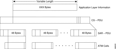
Data is received from the various applications layers by the Convergence Sub-Layer and mapped into the Segmentation and Reassembly Sub-Layer. User information, typically of variable length, is packetized into data packets called Convergence Sublayer Protocol Data Units (CS-PDUs). Depending on the Adaptation Layer, these variable length CS-PDUs will have a short header, trailer, a small amount of padding, and may have a checksum.
The Segmentation and Reassembly Sub-Layer (SAR) receives these CS-PDUs from the Convergence Sub-Layer and segments them into one or more 48-byte SAR-PDUs, which can be carried in the 48-byte ATM information payload bucket. The SAR-PDU maps directly into the 48-byte payload of the ATM cell transmitted by the Physical Layer. Figure 8-9 illustrates an example of the Adaptation Process.
Current implementation of ATM is based on setting up permanent virtual circuits (PVCs). PVCs are defined when the user adds the connection to the network. The routing is programmed by the network operator into routing tables and the circuit operating parameters are assigned. However, the circuit does not utilize any network bandwidth until there is traffic to be carried. Since they resemble nailed up voice connections, there is no signaling requirements for setting up PVCs.
Switched virtual circuits, on the other hand, are established on request by the user and are removed from the network database(s) upon completion of the transmission. In this respect, they resemble dial-up voice connections and are under control of the user. ATM standards for support SVCs are under development.
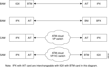
The IPX/IGX connect to a BPX or other ATM switch via an AIT/BTM T3 or E3 trunk.The AIT(IPX) or BTM (IGX) can operate in several different addressing modes selected by the user (see Table 8-4 and Figure 8-10). The BPX Addressing Mode (BAM) is used for all StrataCom ATM Networks. To allow the IPX or IGX to be used in mixed networks with other ATM switches, there are two other addressing modes available, Cloud Addressing Mode (CAM) and Simple Addressing Mode (SAM).
In the BPX Addressing Mode (BAM), used for all StrataCom networks, the system software determines VPI and VCI values for each connection that is added to the network. The user enters the beginning and end points of the connection and the software automatically programs routing tables in each node that will carry the connection to translate the VPI/VCI address. The user does not need to enter anything more. This mode uses the STI header format and can support all of the optional StrataCom features.
In the Simple Addressing Mode, the user must manually program the path whole address, both VPI and VCI values.
The Cloud Addressing Mode is used in mixed networks where the virtual path addresses are programmed by the user and the switch decodes the VCI address. Both CAM and SAM utilize the UNI header type.
| Addressing Mode | Hdr. Type | Derivation of VPI/VCI | Where Used |
|---|---|---|---|
BAM—BPX Addressing Mode | STI | VPI/VCI = Node Derived Address | Between IPX (or IGX) and BPX nodes, or between IPX (or IGX) nodes. |
CAM—Cloud Addressing Mode | UNI | VPI = User Programmed | IPX to IPX (or IGX) connections over networks using ATM switches that switch on VPI only. VPI is manually programmed by user. Terminating IPX converts VCI address to FastPacket address. |
SAM—Simple Addressing Mode | UNI | VPI/VCI = User Programmed | IPX to IPX (or IGX) connections over networks using ATM switches that switch where all routing is manually programmed by user, both VPI and VCI. |
A specialized adaptation that is of particular interest to users of StrataCom equipment is the adaptation of IPX FastPackets to ATM cells. There are a large number of narrowband IPX networks currently in existence that are efficiently carrying voice, video, data, and frame relay. A means must be provided to allow these networks to grow by providing a migration path to broadband.
Since FastPackets are already a form of cell relay, the adaptation of FastPackets to ATM cells is relatively simple.
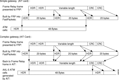
With the Simple Gateway protocol, the AIT card in the IPX (or BTM in the IGX) loads 24-byte FastPacket cells into ATM cells in ways that are consistent with each application. (Each of the two FastPacket cells loaded into the ATM Cell is loaded in its entirety, including the FastPacket header.) For example, two FastPackets can be loaded into one ATM cell provided they both have the same destination. This adaptation is performed by the IPX AIT card or the IGX BTM card.
The AIT (or BTM) is configured to wait a given interval for a second FastPacket to combine in one ATM cell for each FastPacket type. The cell is transmitted half full if the wait interval expires. High priority and non-time stamped packets are given a short wait interval. High priority FastPackets will not wait for a second FastPacket. The ATM trunk interface will always wait for frame relay data (bursty data) to send two packets. NPC traffic will always have two FastPackets in an ATM cell.
Starting with Release 8.1, with the Complex Gateway capability, the FRSM card in the AXIS, the AIT card in the IPX (or BTM card in the IGX) streams the frame relay data into ATM cells, cell after cell, until the frame has been completely transmitted. Since only the data from the FastPacket is loaded, the Complex Gateway is an efficient mechanism. Also, discard eligibility information carried by the frame relay bit is mapped to the ATM cell CLP bit, and vice versa. See Chapter 14 for further information on frame relay to ATM interworking. A comparison of the simple gateway and complex gateway formats is shown in Figure 8-11.
An ATM switch is conceptually a simple device taking ATM cells from an input port and transferring them to an output. Routing of cells through an ATM switch is directed by tables that interpret the VPI/VCI addresses in the ATM cell header. The simplicity of ATM switching is one of the advantages that promotes its use in broadband networking.
There are two fundamental types of ATM switches, those utilizing a bus architecture and those using a matrix switching fabric. Bus-based ATM switches are primarily utilized in LAN equipment since they are limited in backplane speeds but easily support multicasting (a requirement of LAN equipment). Bus type switches are referred to as shared media switches as the bandwidth is shared among all users.
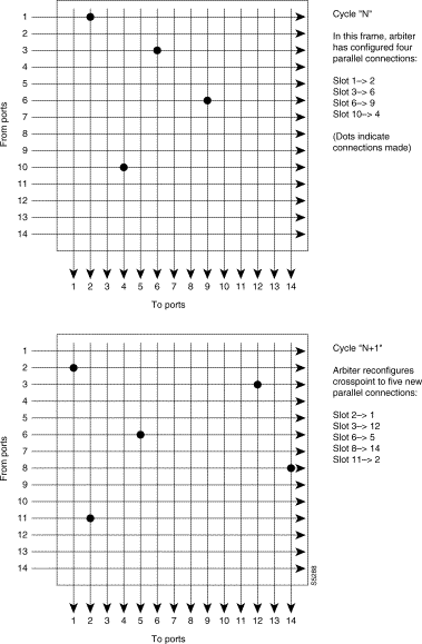
The BCC controller card in the BPX utilizes either a 16 X 16 or 16 X 32 crosspoint switch implemented with a very high speed VLSI switching device. With the BCC-3, which employs a 16 x 16 crosspoint switch, the BPX operates at 9.6 Gbps. With the BCC-4, which employs a 16 x 32 crosspoint switch, the BPX can operate at 19.6 Gbps when it is also equipped with BXM cards. The crosspoint switch is under control of an arbiter that takes requests from each port with traffic waiting to be switched and sets up the appropriate crosspoint. Multiple crosspoints are operated simultaneously at each switch cycle to connect various input and output ports as long as there is no contention for a particular crosspoint. Figure 8-12 illustrates several typical cycles of a 16 X 16 crosspoint matrix.
The arbiter polling is programmed by system software to insure each port is given equal access to the switch matrix. If there are cells from several input ports destined for the same output port, the arbiter selects one of the inputs on one switch cycle and grants access to another input at a later cycle to prevent switch contention (and resulting blocking). A small buffer at each input temporarily holds the ATM cells to prevent loss of cells in this situation
The following paragraphs describe the digital line format for various types of digital transmission lines used to transmit ATM cells throughout StrataCom networks. These lines operate at data rates of typically 45 Mbps and higher and are referred to as broadband.
T3 trunks can be used for transmission of packets on links requiring higher capacity than is available with T1 lines. They operate at the DS3 bit rate of 44.736 Mbps. Because of the higher bit rate, T3 trunks are generally carried over fiberoptic or digital microwave.
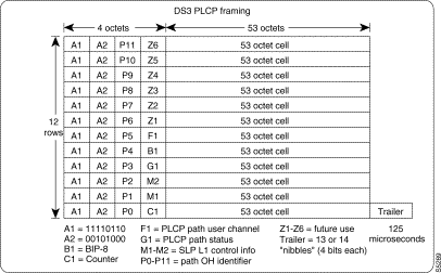
Transport of ATM cells at the DS3 rate is accomplished using the Switched Multimegabit Data Services (SMDS) Physical Layer Convergence Protocol (PLCP) framing structure as defined in IEEE 802.6 and Bellcore TR-TSV-000773 specifications. The DS3 M-frame pattern is observed, but there is no direct correlation between M-frames and PLCP framing. Figure 8-13 illustrates the DS3 PLCP Frame Sequence.
The DS3 PLCP frames occur at a rate of 8000 per second, or one every 125 µsec. Since one DS3 PLCP frame can carry twelve 53-octet cells, the bandwidth capacity in cells per second rate for DS3 trunks is (8000 frames/sec x 12 cells/frame = 96,000 cells per sec.). Since the T3 signal is bipolar, it carries the clocking along with the data just as is done with T1. The node recovers receive clock and uses it to clock in the receive data. The signal is B3ZS encoded (similar to the B8ZS used on T1) to scramble the bit stream to eliminate long strings of "0"s or "1"s so that ones density requirement of T1 is not a consideration.
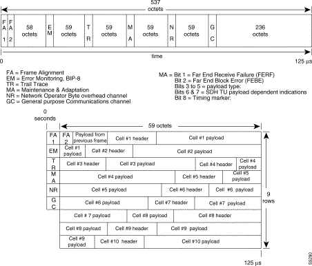
Transport of ATM cells at the E3 rate is accomplished using a framing structure as defined in ITU-T (CCITT) recommendations G.832 and G.804. The frame consists of 537 octets (8-bit bytes) with 7 bytes of overhead occurring every 125 µsec. Figure 8-14 illustrates this frame format. StrataCom nodes monitor the two frame alignment octets and set the MA payload bits to ATM and does nothing with the remaining overhead bits.
The G.804 frame can transmit 10 ATM cells and so the bandwidth of the E3 trunks is (8000 frames/sec. x 10 cells/frame = 80,000 cells/sec.) The ATM cells are arranged in 9 rows of 59 octets each and cell #1 is not constrained to begin immediately following the frame alignment octets. This frame structure is not compatible with earlier ITU-T recommendations for E3 lines.
E3 trunks encode the data in a form called HDB3, which also eliminates long strings of zeros. Error monitoring is provided in the Error Monitoring octet which is an 8-bit number representing the Bit Interleaved Parity (BIP-8) for the bits in the previous frame.
A virtual trunk may be defined as a "trunk over a public ATM service". The trunk really doesn't exist as a physical line in the network. Rather, an additional level of reference, called a virtual trunk number, is used to differentiate the virtual trunks found within a physical trunk port.
With only a single trunk port attached to a single ATM port in the cloud, a node uses the virtual trunks to connect to multiple destination nodes on the other side of the cloud.
Since a virtual trunk is defined within a trunk port, its physical characteristics are derived from the port. All the virtual trunks within a port have the same port attributes.
(Note: All port and trunk attributes of a trunk are configured with cnftrk or cnftrkparm)
In Release 8.2, a BNI T3/E3 or BNI-155 (OC3) trunk from the StrataCom network connects to an ATM UNI interface at the Public Network ATM Cloud. If the cloud uses StrataCom equipment, this UNI interface is provided by an ASI-T3/E3 or ASI-155 (OC3). Trunk and channel capacities are as follows:
In order for a virtual trunk to successfully transmit data through the ATM cloud, the ATM equipment in the cloud must support Virtual Path switching and transmit incoming cells based on the VPI in the cell header.
A virtual path connection (VPC) is configured in the cloud to join two endpoints. The VPC can support either CBR, VBR, or ABR traffic. A unique VPI per each VPC is used to move data from one endpoint to the other. The StrataCom equipment at the edge of the cloud transmits cells which match the VPCs VPI value. As a result the cells are switched to the other end of the cloud.
Within the ATM cloud one virtual trunk is equivalent to one VPC. Since the VPC is switched with just the VPI value, the 16 VCI bits (from the ATM-UNI format) of the ATM cell header are passed transparently through to the other end.
If the public ATM cloud consists of BPX nodes, the access points to the cloud are ASI ATM-UNI ports. Since the cells transmitted to the ASI trunk interface are coming from a StrataCom device, e.g., BNI card, the 16 VCI bits have already been left shifted by 4 bits and contain 12 bits of VCI information and 4 bits of ForeSight information. Therefore, the ASI cards at either end of the cloud and of the VPC are configured not to shift the VCI when formatting the cells with an STI header for transport through the cloud. (Note: The command cnfport is modified to allow the user to configure "no shifting" on the ASI port. BPX software Release 8.2 is required to support this new configuration.)
If the ATM cloud consists of non-StrataCom nodes, then the 12 VCI + 4 Foresight bits in the cells coming from the BNI card in the BPX are passed through untouched as 16 VCI bits. Since it is a non-StrataCom network, the ForeSight bits are ignored.
All types of StrataCom traffic are supported over virtual trunks through an ATM cloud. Every trunk is defaulted to carry every type of traffic. The CBR, VBR, ABR, and UBR virtual trunks within the cloud should be configured to carry the correct type of traffic. The recommended traffic configurations are as follows:
· CBR Trunk: | ATM CBR traffic, voice/data traffic |
· VBR Trunk: | ATM VBR traffic, frame relay traffic |
· ABR Trunk: | ATM ABR traffic, frame relay ForeSight traffic |
· UBR Trunk: | ATM UBR traffic |
The CBR trunk is best suited to carry delay sensitive traffic such as IPX voice/data and BPX CBR traffic. The VBR trunk is best suited to carry IPX frame relay and BPX VBR traffic. The ABR trunk is best suited to carry IPX ForeSight and BPX ABR traffic. The user can change the types of traffic each trunk carries. However, to avoid unpredictable results, it is best to conform to the recommended traffic types for a given type of VPC.
A user can configure any number of virtual trunks between two ports up to the maximum number of virtual trunks per port and the maximum number of logical trunks per node. These trunks can be any of the three trunk types, CBR, VBR, or ABR.
Cells transmitted to a virtual trunk use the standard ATM-UNI cell format. Because of the UNI format, two types of information found in the STI header are no longer available in cells received from a virtual trunk. The Header Control Field (HCF) is unavailable by definition of the UNI format. The payload information is removed to increase the number of VCI bits from 8 to 12 per VPI.
Connection (non-path) traffic—The connection identifier is stored in the VCI as shown in Figure 8-15.

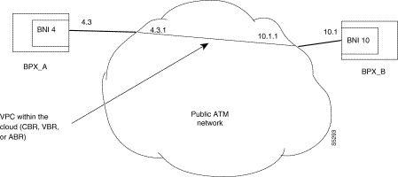
The following example describes a typical scenario of adding one virtual trunk across an ATM network (Figure 8-16). On one side of the cloud is BPX_A with a BNI trunk card in slot 4. On the other side of the cloud is BPX_B with a BNI trunk card in slot 10. A virtual trunk is added between port 4.3 on the BNI in BPX_A and port 10.1 on the BNI in BPX_B.
A VPC within the cloud must be configured first.
· BPX_A | uptrk 4.3.1 | up virtual trunk #1 on BNI trunk port 4.3 |
· BPX_A | cnftrk 4.3.1 | configure VPI, VPC type, traffic classes, # of |
|
| connection channels |
· BPX_B | uptrk 10.1.1 | up virtual trunk #1 on BNI trunk port 10.1 |
· BPX_B | cnftrk 10.1.1 | configure VPI, VPC type, traffic classes, # of |
|
| connection channels |
· BPX_A | addtrk 4.3.1 | add the virtual trunk between the two nodes |
|
| (addtrk 10.1.1 at BPX_B would do the same) |
The VPI values chosen during cnftrk must match those used by the cloud VPC. In addition both ends of the virtual trunk must match on VPC type, traffic classes supported, and number of connection channels supported. The addtrk command checks for matching values before allowing the trunk to be added to the network topology.
The network topology from BPX_A's perspective after the trunk addition would be
| BPX_A | 4.3.1 to 10.1.1/BPX_B |
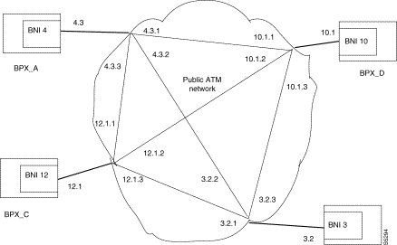
One of the purposes of virtual trunking is to increase the efficiency of connectivity through an ATM cloud. The following example describes how virtual trunks may be used to fully mesh multiple nodes by attaching them to a cloud.
In this 4-node example, Figure 8-17, only four trunk ports are used to link into the cloud, yet all four nodes are directly connected through the cloud with six virtual trunks. The fanout of three virtual trunk endpoints per port produces a savings of two ports per node.
Adding an additional node to this network would require adding one physical link to the cloud. By increasing the fanout of virtual trunks at each port by one, all the nodes would still be fully connected.
This savings of trunk ports provides a much lower resource cost in using an ATM service to connect a network.
Each virtual trunk consists of one queue (Q_BIN) on the BNI. This queue corresponds to the configured VPC type for the virtual trunk; CBR, VBR or ABR. No distinction is made between the different types of CBR, VBR, and ABR traffic. For example, voice and NTS data traffic are placed into the same CBR queue.
The BNI-T3/E3 contains 32 cell queues per port. The BNI-OC3 contains 12 cell queues per port.
The user commands cnftrk and cnftrkparm are used to configure the one queue within the virtual trunk.
The following statistics are collected for a BNI virtual trunk.
· Cells Sent | · Total cells transmitted |
· CLP Cells Dropped | · Total CLP dropped |
· Overflow Cells Dropped | · Total overflow cells dropped |
· Max Queue Depth | · Maximum queue depth |
Y-Cable redundancy is supported for BNI-T3/E3 trunk cards at the edge of the ATM cloud. For BNI-OC3, Y-redundancy is not supported.
A virtual trunk has alarms which may be generated solely from the trunk itself. These are statistical alarms only.
The following queue statistical alarms are available.
A virtual trunk also has trunk port alarms which are shared with all the other virtual trunks on the port. These alarms are cleared and set together for all the virtual trunks sharing the same port.
A virtual trunk cannot be used as a feeder trunk. Connections cannot be terminated on a feeder trunk. Both of these are restricted at the user interface.
The routing algorithm excludes VPCs from being routed over a virtual trunk. The reason for this restriction is due to how the virtual trunk is defined within the ATM cloud.
The cloud uses a VPC to represent the virtual trunk. Routing an external VPC across a virtual trunk would consist of routing one VPC over another VPC. This use of VPCs is contrary to its standard definition. A VPC should contain multiple VCCs, not another VPC. In order to avoid any non-standard configuration or use of the ATM cloud, VPCs cannot be routed over a virtual trunk through the cloud.
Structured networks and virtual trunking are not allowed to coexist in the same network.
New error messages for virtual trunks.
· "Port does not support virtual trunking" | · Port is not configured for virtual trunks |
· "Port configured for virtual trunking" | · Port is not configured for a physical trunk |
· "Invalid virtual trunk number" | · Virtual trunk number is invalid |
· "Maximum trunks per node has been reached" | · Trunk limit per node has been reached |
· "Invalid virtual trunk VPI" | · Virtual trunk VPI is invalid |
· "Invalid virtual trunk traffic class" | · Virtual trunk traffic class is invalid |
· "Invalid virtual trunk VPC type" | · Virtual trunk VPC type is invalid |
· "Invalid virtual trunk conid capacity" | · Virtual trunk conid capacity is invalid |
· "Mismatched virtual trunk configuration" | · Ends of virtual trunk have different configurations |
BNI virtual trunk:
addtrk | <slot>.<port>.<vtrunk> |
where | <slot> is the BNI slot number |
| <port> is the BNI port number |
| <vtrunk> is the virtual trunk number. |
![]()
![]()
![]()
![]()
![]()
![]()
![]()
![]()
Posted: Thu Jan 18 12:15:39 PST 2001
All contents are Copyright © 1992--2001 Cisco Systems, Inc. All rights reserved.
Important Notices and Privacy Statement.