|
|

This chapter describes how to convert a rack-mounted IGX 16 switch to a rack-mounted IGX 32 switch. The descriptions include steps for AC-powered and DC-powered systems. The steps begin after you have removed all PVCs and turned off power to the node. To do this upgrade, you should have at least basic experience with IGX installation procedures. The topics in this chapter include:
Before you begin removing connections, check the parts list against the actual contents of the upgrade kit. For upgrading an AC-powered system, make sure the appropriate number of additional AC power supplies are in the kit. (Upgrading an AC-powered system requires at least one additional AC power supply.) If you are unsure of the number of required AC supplies, refer to the section titled "Installing the AC Power Supply Assembly" in the chapter titled "Enclosure and Power Installation."
The tools for the upgrade are:
The upgrade kit comes with a tool that has both a number 1 phillips head screwdriver and a 5/32-inch Allen wrench.
 | Warning The following safety requirements must be observed: |
Figure 6-1 shows AC-powered and DC-powered nodes in a STRATM cabinet. Frequently, the components sit higher in the rack than the position in Figure 6-1. Figure 6-2 shows the IGX 32 node in a STRATM cabinet.
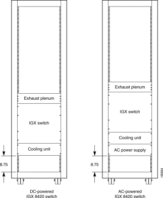
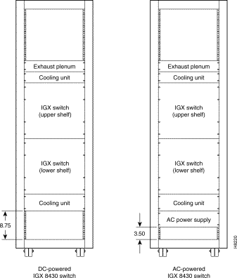
The instructions in this section describe installation with and without a lift. One person alone can complete the upgrade procedure. However, moving the components is easier when you have a mechanical lift capable of holding and maneuvering all components that make up the IGX 32 node.
Whether or not you have a mechanical lift, the following procedures apply to AC and DC systems:
This section describes how to re-locate the IGX 16 components and install the shelf-components in the kit. Figure 6-2 illustrates the result.
Step 1 For an AC-powered system:
Step 2 Reinstall the fan tray (if necessary) so it sits near the bottom of the rack. (If the node is DC-powered and the rack is in a STRATM cabinet, leave at least 3.50 inches of space (8.89 cm or 2 rack mount units) between the bottom of the fan tray and the floor of the cabinet.)
Step 3 Remove the IGX 16 card cage. Remove as many cards as necessary to make the card cage maneuverable, starting with slot 1. Empty at least front slots 1-3 so you have access to the plate that covers the card cage hole.
Step 4 Remove the cover plate over the card cage hole.
Step 5 Install the lower card cage (slots 17-32). The part number for the lower cage ends with -01. If the IGX 16 card cage was positioned low in the rack, the mounting brackets are already in place, otherwise you must first install the brackets from the kit.
Do not install the cards until you have installed the upper card cage and the ribbon cable. The section titled "Connecting the Upper and Lower Card Cages" describes how to install the ribbon cable.
Step 6 Install the upper card cage (slots 1-16). The part number for the upper cage ends with -00.
Step 7 Install the upper (booster) fan tray.
Step 8 Install the exhaust plenum.
Step 9 If the rack configuration uses rear-mount rails, you can move the rear mounting brackets to the opposite side of the node than the normal position. In the new position, the flange on the bracket creates an anchor to hold down the exhaust plenum.
Step 10 Go to the section titled "Connecting the Upper and Lower Card Cages."
This section describes the portions of the upgrade you can facilitate by using a mechanical lift. This section has two parts: the first part describes the order for disconnecting the existing components and stacking these components along with the new components on the lift. The second part describes the order for installing the components on the lift.
When the text in the following steps instructs you to place a component on the lift, it means you place the component on top of any other components that are already on the lift.
Step 1 For an AC-powered system:
Step 2 Place the new card cage (with slots 17-32) on the lift. This card cage has a part number ending in -01.
Step 3 Place the card cage with slots 1-16 on the lift (on top of the card cage with slots 17-32). The card cage with slots 1-16 has a part number ending in -00.
Step 4 Place the booster fan tray on the lift.
Step 5 Place the exhaust plenum on the lift.
Counting from the bottom to the top, the order of the components on the lift should be as follows (item 1 in the list is the bottom item, item 2 sits on top of item 1, and so on):
1. Optional AC power assembly
2. Main (lower) cooling unit
3. Lower card cage (slots 17-32). The part number of the lower card cage ends with "-01."
4. Upper card cage (slots 1-16). The part number of the upper card cage ends with "-00."
5. Upper cooling unit (also called booster fan unit)
6. Exhaust plenum
At this point, the components that make up an IGX 32 node are ready for you to install.
The distance between the bottom of the rack and the bottom of the lowest component depends on user-requirements, such as the presence of an AC power assembly or other components in the rack. Also, for a STRATM cabinet, the distance between the bottom of the lowest component and the floor of the cabinet should be at least 3.50 inches (8.89 cm. or 2 rack mount units). The height of each StrataCom component appears in the appendix titled "Cisco Cabinet Dimensions."
Step 1 If you have not already done so, lower the lift to a height suitable for the configuration.
Step 2 Attach the exhaust plenum to the rack. Lower the lift only enough to install booster.
Step 3 Attach the booster fan tray to the rack. Lower the components enough to provide room for lifting the next component into position.
Step 4 Attach the upper card cage to the rack. Lower the components enough so the top of lower card cage is flush with the bottom of upper cage.
Step 5 Attach the lower card cage to the rack. Lower the components enough to provide room for lifting the next component into position.
Step 6 Maneuver lift so the main fan tray is flush with the card cage and so the screw holes align.
Step 7 If present, attach the AC power assembly. For a mid-mount rack only, attach the tray to the mounting brackets with the head of each mounting screw on the inside of the tray and each associated nut on the outside of the bracket.
Step 8 If the system is AC-powered, install the new power supplies from the kit.
Step 9 Attach the new door from the kit to the bottom card cage.
Step 10 Go to the section titled "Connecting the Upper and Lower Card Cages."
To extend the backplane from the upper card cage to the lower card cage, install the folded ribbon cable as the following steps describe. The ribbon cables pass through the card cage holes. The cables connect to two, 100-pin connectors on the front of each backplane.
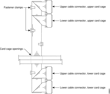
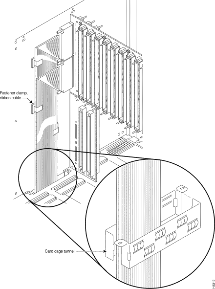
The order of the tasks in the following steps provides the easiest way for you to install the ribbon cable. Refer to Figure 6-3 and Figure 6-4 as you proceed.
Step 1 If you have not done so, remove the cover plates that cover the card cage holes. The holes are at the bottom of the upper card cage to the left of slot 1 and at the top of the lower card cage to the left of slot 17.
Step 2 While you hold the cables in the space above the card cage hole in the upper card cage, drop the connectors for the bottom card cage through the card cage holes. Let the lower connectors hang until you have connected the upper connectors (the next step).
Step 3 Screw in the connectors for the upper card cage, as follows:
Attach the top connector of the upper cable.
Attach the top connector of the lower cable.
Step 4 Screw in the connectors for the lower card cage, as follows:
Attach the bottom connector of the upper cable.
Attach the bottom connector of the lower cable.
Step 5 A two-piece conduit called the card cage tunnel surrounds the ribbon cables and sits in the card cage hole. Figure 6-4 shows the card cage tunnel installed and, in the expanded view, prior to installation. Fit the pieces of the card cage tunnel around the ribbon cables and screw this unified piece into the card cage hole.
Step 6 Use the fastener clamps to secure the ribbon cables:
Remove the plastic back of each fastener clamp just before you attach it to the cable.
Slip the ribbon cables through the fastener clamps.
Attach the fastener clamps to the side of the card cage.
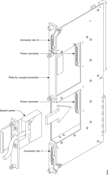
This section describes how to connect power cables for the fan trays. Figure 6-5 shows the fan power cables and their connection points. The booster fan tray in the kit comes with the power cable connected to it, so you need only to connect the cable to the upper Power Entry Back Card (PE-BC). The cable for the main (lower) fan tray has a Y-configuration with a short branch and a long branch.

Step 1 If you have not already done so, discard the old fan power cable that connected power to the IGX 16 fan tray (now the lower fan tray).
Step 2 Connect the booster fan cable to the upper fan power connector on the PE-BC. See Figure 6-5. The booster fan power connector on the upper PE-BC is labeled "fan 2." The cable comes already attached to the fan tray in the kit.
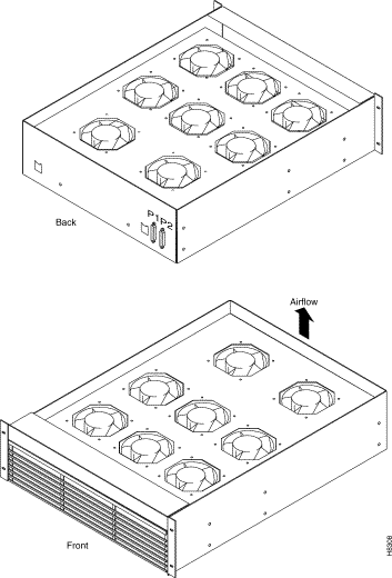
Step 3 At the main fan tray, attach connector P1 on the cable to connector P1 on the fan tray. Attach connector P2 on the cable to connector P2 on the fan tray. These connectors are keyed and have a built-in latch. See Figure 6-6 for front and back views of the main fan tray. Note that the booster fan tray in the kit has no grille.
Step 4 Attach the clamp on each fan tray clamp to the chassis.
Step 5 Connect the main fan power cables to the fan power connectors labeled "fan 1" on the upper and lower PE-BCs. See Figure 6-5.
Step 6 For the main fan tray, attach the air intake grille.
Step 7 Attach the optional cable managers if appropriate. The kit contains a new cable manager.
Step 8 If the system is AC-powered, go to the section titled "Connecting AC Power."
Step 9 If the system is DC-powered, go to the section titled "Connecting DC Power."
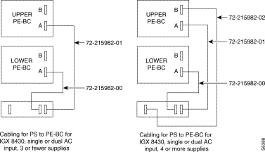
This section describes how to set up AC power. At this point, you have already installed the AC power supplies and the new PE-BC, so the steps begin by describing how to connect the system power cables. Use Figure 6-7 to see the cable arrangements according to the AC power configuration.
Step 1 Attach each system power cable at the AC power assembly. Figure 6-8 shows the connectors for each shelf at the back of the AC power assembly.
Step 2 Insert each system power connector to its designated receptacle. Figure 6-9 shows both used and unused connectors. Secure the power connector with the captive screw.
Step 3 On the PE-BCs, attach the blank faceplates to cover any unused connectors. Figure 6-9 shows a blank faceplate over an unused connector.
Step 4 Connect the appropriate number of AC power cords.
Step 5 After you have turned on the power and verified that the AC Okay and DC Okay LEDS are lit, turn off the power and proceed to the section titled "Installing Cards and Cables."

This section describes the steps for adding the Power Entry Modules (PEMs) to the new Power Entry Back Card (PE-BC). Refer to Figure 6-10 for the steps that follow. If you are not sure if the site can provide the necessary DC current, refer to the sections on DC power in the chapter titled "Enclosure and Power Installation."
Step 1 Make sure all the circuit breakers on the PEMs are in the OFF position.
Step 2 Install the new PE-BC.
Step 3 Slide in each new PEM until it seats in the D-connector on the new PE-BC.
Step 4 Tighten the screws to secure the PEM in the PE-BC.
Step 5 Place the wiring within the strain relief mechanism.
Step 6 Plug in the terminal wiring block into the DC receptacle.
Step 7 Attach a blank coverplate over any unused connector.
Step 8 Switch the circuit breaker on the PEM to the ON position.
Step 9 Verify correct system voltage levels.
Step 10 Turn off power until you have installed the cards and cabling as described in the section titled "Installing Cards and Cables."

Install the front and back cards. If you do not know how to install the cards, refer to the descriptions in the chapter titled "Card Installation and Node Startup." This section contains some reminders for card installation.
 | Warning Correct alignment between connector pins and receptacles is extremely important. Before inserting a card, make sure all backplane pins are straight. Make sure the connectors on the card and backplane are aligned. Insert card gently. |
After you have installed the cables, start up the system. If necessary, refer to the IGX start-up instructions in the chapter titled "Card Installation and Node Startup." Executing the dsppwr command should show normal power operation.
After system operation appears to be normal, install the new cable guard.
![]()
![]()
![]()
![]()
![]()
![]()
![]()
![]()
Posted: Tue Oct 15 14:18:41 PDT 2002
All contents are Copyright © 1992--2002 Cisco Systems, Inc. All rights reserved.
Important Notices and Privacy Statement.