|
|

Before installing the system, verify that all ordered parts are present and in good condition. If anything is missing or damaged, report it to a StrataCom Order Administration.
Check the cabinet for the following inventory:
_____ | [IGX 16/32] The unit has the correct number of card cages (1 or 2). |
|---|---|
_____ | The unit has the correct power type (AC or DC) and the factory-installed Power Entry Back Cards (PE-BC), one per shelf. For DC-powered systems, DC PEMs are factory-installed in each PE-BC. For an AC system, check for the power supply tray and correct number of power supplies and cables. |
Make sure all purchased cards are present. Check the number and type of cards shipped against the number and type of card purchased.
_____ | Correct number of NPMs | _____ | Correct number of AIT-T3s |
_____ | Correct number of NTMs | _____ | Correct number of AIT-E3s |
_____ | Correct number of BTMs | _____ | Correct number of BC-T1s |
_____ | Correct number and types of CVMs | _____ | Correct number of BC-E1s |
_____ | Correct number and types of FRMs | _____ | Correct number of BC-J1s |
_____ | Correct number of FTMs | _____ | Correct number of BC-Y1s |
_____ | Correct number of HDMs | _____ | Correct number of BC-SRs |
_____ | Correct number of LDMs | _____ | Correct number of FRIs |
_____ | Correct number of LDIs | _____ | Correct number of FPCs |
_____ | Blank faceplates for unused back card slots | _____ | Correct number of SDIs |
_____ | Correct number of ARMs | _____ | Correct number of ARIs |
An inventory list of the installed cards is shipped with the unit. The list includes each card's serial number, revision number, and slot number (serial and revision numbers are also found on the solder side of each card). Check for the presence of any other pieces on the shipping list. After verifying that the correct cards are present, tape a copy of the inventory list to the back of this manual.
The IGX 16/32 site must satisfy the following requirements.
To provide some protection against seismic activity, the feet and wheels of the IGX stand-alone cabinets can be removed to permit the cabinet to be bolted to a concrete floor or to a structural member in the floor.
In STRATM cabinets, provisions are available for seismic anchoring. Holes exist in the upper and lower corners for 3/8" or 1/2" bolts. Also, an optional stability plate can be purchased with the STRATM cabinet. The stability plate is bolted to the floor, then the STRATM cabinet is bolted to the stability plate. The "STRATM Seismic Anchoring" section contains instructions for installing the seismic stability plate.
 | Warning The following safety requirements must be observed: |
This section lists the requirements that relate to electrical power and grounding. These requirements cover installations at Central Office (CO) and Private Enterprise locations.
An AC power source must be available within 6 feet (1.8 m) of the system and very accessible. Before turning on the power, verify that the power supplied to the node comes from a dedicated branch circuit.
The receptacles that the IGX plug into must be of the grounding type. The grounding conductors that connect to the receptacles should connect to protective earth at the service equipment.
Only a -48 VDC supply that complies with the Safety Extra Low Voltage (SELV) requirements of EN 60950 can connect to the IGX DC input.
For DC supply connections, 10 to 12 AWG (or a metric equivalent of 4 sq. mm) should be used. Individual national codes for proper conductor sizing may apply. The conductors must be suitable for 25 Amps.
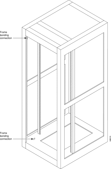
To maintain the full EMI and EMC integrity of this equipment, it must be bonded to an Integrated Ground Plane or an Isolated Ground Plane network. The purpose of this is to mitigate the damaging effects to equipment from Electrostatic Discharge and Lightning. Refer to the latest edition of ITU Recommendation K.27 or Bellcore GR-1089-CORE requirements to ensure that the correct Bonding and Grounding procedures are followed. As recommended in these documents, a frame bonding connection is provided on the StrataCom STRATM cabinet for rack-mounted systems and on the stand-alone cabinets.
Refer to the section "Making the Frame Bonding (Ground) Connection ," for information on the locations of the frame bonding connections and how to make a connection.
Except for the AC power supply module, every module in a rack-mount system relies on the rack itself for grounding. Therefore, the rack must be properly connected to protective earth before operating the system.
A DC powered IGX system must have grounding conductors connected at two separate locations, as follows:
These requirements may be relevant to a private network connected to the public switched networks in some international service areas.
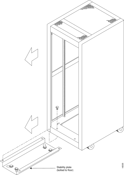
This section describes installing the STRATM cabinet with the optional stability plate for seismic anchoring. If the stability plate is not present, go to the next section. To set up the STRATM cabinet with the stability plate:
Step 1 Use the dimensions in Figure 3-1 to drill the holes for installing the stability plate.
Step 2 Remove the stability plate from the inside-bottom of the STRATM cabinet. Save these nuts and bolts.
Step 3 With the user-provided anchoring bolts, attach the stability plate to the floor.
Step 4 Roll the STRATM cabinet over the stability plate as Figure 3-2 illustrates.
Step 5 Using the nuts and bolts from the shipping setup, secure the STRATM cabinet to the stability plate.

Installing an IGX requires the following tools and equipment:
Rack-mount systems come with the parts described in the assembly instructions. As the instructions for DC-powered systems explain, the user provides the DC-power cable.
StrataCom stand-alone systems come with all components installed in the cabinet. So, the installation steps consist of placing the unit at its operational location, unpacking it, and verifying the structural and power connection integrity before turning on the power. Note that a stand-alone cabinet is 19.9" wide. The adjustable levelers require a 5/8" wrench. If the system has an AC power source, go to the "AC Power Connections"section. If the system has a DC power source, go to the "DC Power Connections" section.
The rack-mount IGX 16 fits in a 19 inch (48.25 cm.) rack. The front of each assembly chassis has flanges that serve as the front mounting brackets. The assembly kit contains other brackets for different mounting setups. The following order of component installation is the most convenient and efficient. For some of these components, separation sections are named that contain detailed installation steps.
1. Optional AC power assembly
2. Cooling unit
3. Card cage
4. Exhaust plenum
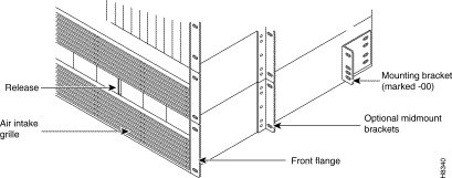
The miscellaneous parts kit for rack systems contains brackets for both a STRATM cabinet and a user-supplied rack. The kit includes mid-mount brackets for open racks.
The rear-mount brackets attach to the rear vertical rail in a STRATM cabinet. Each of these brackets has a horizontal flange upon which the back of each IGX component rests. The front of each assembly chassis has flanges that serve as the front mounting brackets.
 | Caution If an IGX is mounted in a user-supplied cabinet, be sure an unrestricted air flow is available in and out of the enclosure. If necessary, contact the ISC for assistance. |
Step 1 Decide on the IGX location. See Figure 3-3 for dimensions (Figure 3-4 for metric).
| Caution When moving a STRATM cabinet, do not push the cabinet at its sides. Instead, grip its front or back edges. |
Step 2 To install the optional AC power supply kit, do the steps in the "Installing the AC Power Supply Assembly" section later in this chapter.
Step 3 To install the cooling unit, do the steps in the "Installing the Cooling Unit" section later in this chapter.
Step 4 Position the IGX card cage so that the back of it faces the rack.
| Caution An empty IGX card cage weighs 75 pounds (34 Kgs.) and requires a 2 or 3-person lift to move into place. |

Step 5 With one person on each side of the card cage, lift and slide it into the rack.
Step 6 Attach the cabinet to the rack with 8 #10-32 machine screws (from the kit).
Step 7 If the system is DC-powered, see the "DC Power Connections"section. For AC-powered systems, see the "Installing the AC Power Supply Assembly" section.
| Caution Make sure that mounting the equipment does not create a hazardous condition due to uneven mechanical loading. The equipment rack should be securely supported. |
The IGX 32 is designed for mounting in a 19 inch (48.25 cm.) equipment rack. The following order of component installation is the most convenient and efficient. For some of these components, separation sections are named that contain detailed installation steps.
1. Optional AC power assembly
2. Lower cooling unit
3. Lower card cage
4. Upper card cage
5. Ribbon cables for connecting upper and lower backplanes
6. Card cage tunnel around backplane ribbon cables
7. Upper cooling unit (also called booster fan unit)
8. Exhaust plenum
The miscellaneous parts kit contains brackets for rack-mounting in either a STRATM cabinet or a user-supplied rack. The kit includes mid-mount brackets for open racks. For a STRATM cabinet, the rear-mount brackets attach to the rear vertical rail. Each of these brackets has a horizontal flange upon which the back of an individual component rests. The front of each assembly chassis has flanges that serve as front mounting brackets.
| Caution If an IGX goes in a user-supplied cabinet, be sure air can freely flow in and out of the enclosure. |
| Caution When moving a STRATM cabinet, do not push the cabinet at its sides. Instead, grip the front or back edges. |
Step 1 Refer to Figure 3-4 for component dimensions. Note that, although Figure 3-4 shows mid-mount and rear-mount brackets, these brackets are not normally used together.
Step 2 To install the optional AC power supply kit, do the steps in the "Installing the AC Power Supply Assembly" section next.
Step 3 To install the cooling unit, do the steps in the "Installing the Cooling Unit" section later in this chapter.
Step 4 Install the brackets for the card cages.
Step 5 Position the IGX card cage so the back of it faces the front of the cabinet.
| Caution An empty card cage requires a 2 or 3-person lift to move. |
Step 6 With one person on each side of the card cage, lift it into the rack. In a STRATM cabinet, rest the back of the card cage on the rear-bracket flange.
When mid-mount brackets are used, screw the card cage to the brackets with #10-32 machine screws from the miscellaneous parts kit.
Step 7 Secure the front of the card cage to the front of the rack with #10-32 machine screws from the miscellaneous parts kit.
| Warning Make sure that mounting the equipment does not create a hazardous condition due to uneven mechanical loading. The equipment rack should be securely supported. |
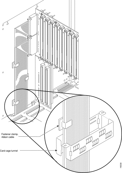
Step 8 The folded ribbon cables that connect the upper and lower backplanes pass through a cut-out space in the card cages. The cables connect to two, 100-pin connectors on the front of each backplane. See Figure 3-5. If NPM cards are present, these and possibly other front cards need removing prior to ribbon cable installation.
Connect the cable from the upper connector of the upper backplane to the upper connector in the lower backplane.
Connect the cable from the lower connector of the upper backplane to the lower connector in the lower backplane.
Step 9 A two-piece conduit called the card cage tunnel surrounds the ribbon cables and sits in the cut-out space of the card cages. Fit the pieces of the card cage tunnel around the ribbon cables and screw this unified piece into the cut-out space. Figure 3-5 shows the card cage tunnel in its normal location and prior to assembly.
Step 10 Slip the ribbon cables through the fastener clamps, then attach the fastener clamps (which include a self-adhesive base) to the side of the card cage. See Figure 3-5.
Step 11 If this is an AC-powered system, do the procedures in the "Installing the AC Power Supply Assembly" section later in this chapter.
Step 12 If this is a DC-powered system, go to the "DC Power Connections" section later in this chapter.
The AC power supply assembly consists of the following items:
Power supply installation or replacement requires the following tools:
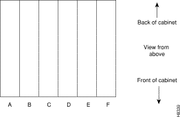
The setup for power supplies depends on the number of AC power inputs, the IGX model, and the number of cards in the system. The minimum configuration is one AC source and one supply. This minimum number applies to the IGX 16: with 12 or fewer cards, 1 supply is enough. Figure 3-6 illustrates the alphanumeric slot designations in a full tray. The paragraphs that follow refer to these designations.
Two types of redundancy exist in the AC power supply configuration. One redundancy is that of AC power inputs. A redundant AC power source from a building circuit that is separate from the other AC circuit provides backup if one AC circuit at the site fails. The other redundancy is that of the 875-Watt power supply modules. Redundancy of the 875-Watt supplies provides a backup if a supply fails.
In supporting the two types of redundancy, power supply arrangements differ, as follows:
Table 3-1 shows the required number of power supplies for the different IGX systems. In Table 3-1 , the locations for primary (or minimal) power supplies are marked with an X. The primary supplies reflect redundancy of AC inputs and backup supplies. An O indicates a slot that must have a supply because the card cage contains more than 12 cards.
In Table 3-1 , the System column lists the IGX model number coupled with the number of AC inputs and whether the single-AC input models have power supply redundancy. The table also shows the slot locations A through F and the part number of the kit that contains all the pieces for the item in the System column. Extra supplies for more than 12 cards (O) are not a part of a kit under Kit Part No. but have another part number. The part number of a supply ordered to fill extra power demands is IGX-AC-PS.
| System | A | B | C | D | E | F | Kit Part No. |
|---|---|---|---|---|---|---|---|
IGX 16: 1 AC input, no power supply redundancy | X | O |
|
|
|
| IGX16-AC1-1 |
IGX 16: 1 AC input, with power supply redundancy | X | X | O |
|
|
| IGX16-AC2-1 |
IGX 16: 2 AC inputs | X | O |
| X | O |
| IGX16-AC2-2 |
IGX 32:1 AC input, no power supply redundancy | X | X | O |
|
|
| IGX32-AC2-1 |
IGX 32: 1 AC input, with power supply redundancy | X | X | X | O |
|
| IGX32-AC4-1 |
IGX 32: 2 AC inputs | X | X | O | X | X | O | IGX32-AC4-2 |
Note that, with all power supply configurations, locations for the power supplies begin at the lowest lettered slot on either side, and the occupied positions are contiguous. For example, in a dual AC system, insert a supply in A, B, D, and E.
Step 1 Attach the mounting brackets to the frame. For illustrative purposes, Figure 3-7 shows mounting brackets at mid-frame and the back (using rear and mid-mount brackets is not a likely configuration). In this view of the cabinet, the rear bracket shown is labeled with a -00. Brackets on the other side of the system a -01.
Step 2 This step may require more than one person. If rear-mount brackets are used, slide in the power supply tray so its back rests on the rear bracket.
For a mid-mount rack only, attach the tray to the mounting brackets with the head of each mounting screw on the inside of the tray and each associated nut on the outside of the bracket.
Step 3 Secure the front of the power supply tray with the front screws. When tightening each of the front screws, hold the adjacent front flange of the tray slightly to the outside so the hinged door can freely open and close. See "Front Flange" in Figure 3-7. The space between the right-angle edge of the flange and the edge of the hinged door should be approximately the width of a thumbnail.
Step 4 Install the power supplies. See Figure 3-8 for an illustration of a power supply. When a power supply almost reaches the end of the slot in the tray, a slight resistance is encountered. Push the power supply slightly farther in to achieve the final position and full connector mating.
Step 5 At the front of each supply, secure the supply to the tray by tightening the captive screw at the bottom/front of the supply.

Step 6 For slots without a power supply, the hinged door has a removable, dummy panel.
Step 7 Close the hinged door and secure it with the screw at the top-center of the door. For the next step, refer to Figure 3-9, Figure 3-10, and Figure 3-11.
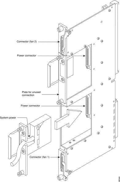
Step 8 Connect the power cables according to the applicable AC configuration shown in Figure 3-9. The cables in Figure 3-9 differ only in length: pinouts are identical. Attach cable 215982-01 from the far right connector—labeled A 1-16 in Figure 3-10—to the lower connector on the upper PE-BC. Figure 3-11 shows where system power connects to the PE-BC. It also shows the blank plate over an unused connection. If power supply trays D-F contain one or more supplies, run cable 215982-02 from the connector on the far left (B 1-16) to the upper connector on the PE-BC. See Figure 3-9 and Figure 3-10. For an IGX 32, run cable 215982-00 from the connector labeled 17-32 to the lower connector on the lower PE-BC.
Step 9 Attach the cable guard and tighten the captive screw at its base.
Step 10 Go to the "Installing the Cooling Unit" section.


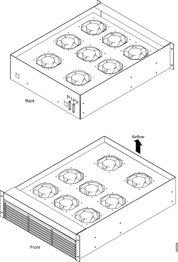
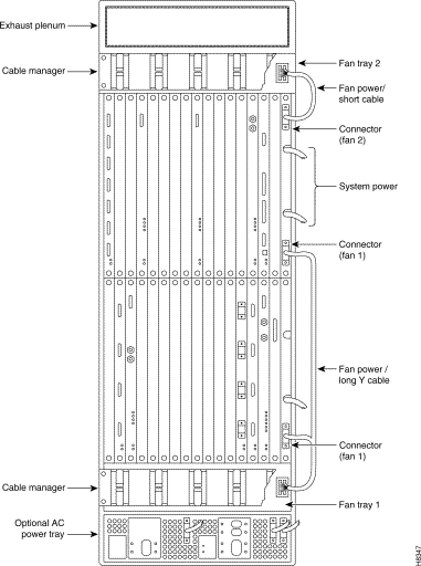
This section describes how to install the main fan tray (Fan Tray 1) in an IGX 16 and 32 and the upper or booster fan tray (Fan Tray 2) in an IGX 32. Figure 3-12 shows the main fan tray. Figure 3-13 shows the locations of Fan Tray 1 and Fan Tray 2 in an IGX 32.
Two cables exist for supplying power to the fans. The short fan power cable is used in both the IGX 16 and the IGX 32. The long "Y" cable is used in the IGX 32 only. See Figure 3-13. In an IGX 16, the short cable connects to connector "Fan 1" of the PE-BC.
In an IGX 32, the short cable goes from the "Fan 2" connector of the upper PE-BC to the power connectors on Fan Tray 2. One branch of the Y cable for Fan Tray 1 is significantly longer than the other branch. The longer branch connects to the "Fan 1" connector of the upper PE-BC. The shorter branch connects to the "Fan 1" connector of the lower PE-BC.
To install the cooling unit assembly:
Step 1 Examine the front and back of the fan tray to be familiar with the setup. Note that, for the bottom fan tray, the captive screws that secure the fan tray are in the front. For the booster fan tray, the captive screws reside at the back of the cabinet.
Step 2 Slide in the cooling unit. and secure it by tightening the four rack screws.
Step 3 On the PE-BCs, plug each D-connector of the appropriate fan power cable into the appropriate PE-BC connector.
Step 4 Plug the power connectors into the fan trays. At the power receptacles on each fan tray, the power connector is a latched housing. Plug P1 into connector P1. Plug P2 into connector P2. Refer to Figure 3-12.
Step 5 Attach the clamp for the fan power cord to the chassis.
Step 6 For lower fan tray installation, attach the air intake bezel.
Step 7 When power is turned on, make sure all fans are running, and execute dsppwr.
Before installing the cards, a step is necessary to indicate to the SCM whether the system is an IGX 16 or an IGX 32. The step consists of either removing or leaving a jumper switch on the SCM. The switch is W6. It sits above component U7P (near the top of connector P2). To indicate an IGX 32, remove the jumper. To indicate an IGX 16, leave the jumper. Make a record of this step so that checking the card later is not necessary.
Y-cable redundancy is a supported feature for many card sets. It requires an extra set of cards and a Y-cable. A set of Y-redundancy commands are also used. For instructions on setting up Y-cable redundancy, refer to the setup section for the specific card set.
| Warning Connector pins must align with receptacles. Before card insertion, make sure that the pins are straight and that the connectors on the card and backplane align with each other. Insert the card gently. It may be necessary to push the edge of the card slightly to one side (this may require removing cards). |
The locations of the cards depend on the hardware configuration. Except for the reserved slots, cards can reside in any slot on the appropriate side of the node. (However, StrataCom recommends that the optional ARM/ARI card set reside in slot 16.) The reserved slots are for the NPMs and SCM. The NPM can reside in front slots 1 and 2. The SCM must reside in back slot 1. Refer to Figure 3-14 for a front view of a shelf in an IGX 16 with 2 NPMs.
The NPM B versions require a minimum level of system software. Refer to the Release Note that comes with this manual to see if the software supports the NPM B version.
An IGX 32 can support a configuration of up to 16 trunk cards. This includes combined NTM and BTM card sets.
The locations for the NPMs and SCMs in an IGX 16 and an IGX 32 are as follows:
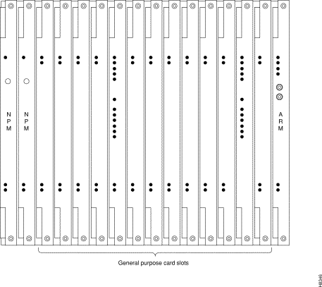
Figure 3-15 shows back card shelves in an IGX 32.
This section contains information on making ground and power connections to the AC and DC powered IGX 16/32 nodes.
| Warning Before connecting power, verify all circuit breakers are off. |
The STRATM cabinet designed by StrataCom comes with attached studs (with hardware for securing a ground conductor to the studs) at the top and bottom of the cabinet for securing the grounding conductors. These studs a 1/4" by 20 threads per inch. Figure 3-16 shows the STRATM cabinet with the ground attachment studs in the upper and lower parts of the cabinet.
A stand-alone cabinet has provisions for mounting grounding conductors on the chassis by screws. In the stand-alone cabinet, this provision is a pair of captive nuts (threaded holes) for the screws on the mounting rail of the chassis (1/4" by 20 threads per inch). Figure 3-17 shows the location of the captive nuts and screws in a stand-alone cabinet for securing in the ground attachments.
The attachment points in the STRATM and stand-alone cabinets are indicated by a ground symbol on the cabinet near the point of attachment.
StrataCom recommends that the stacking order for attaching a ground conductor to the frame is for "an external tooth starwasher" to be placed first onto the stud, followed by the connector terminating the grounding conductor closed-loop ring or two-hole compression fitting, followed by "another external toothed starwasher or lockwasher," and finally a nut.
It is recommended that the stacking order for attaching a ground conductor to the frame is for "an external tooth starwasher" to be placed first onto the screw, followed by the connector terminating the grounding conductor closed-loop ring or two-hole compression fitting, followed by "another external toothed starwasher or lockwasher." This assembly is screwed into the captive nut in the mounting rail beneath the cover plate. See Figure 3-17.

Step 1 Make sure all AC and system power circuit breakers are in the OFF position.
Step 2 Make sure the wiring in the AC plug has the standard relationship shown in Figure 3-18.

Step 3 Plug each power cord into the IEC connector and tighten the screw on the clamping ring. Figure 3-19 shows a single-feed, AC system.
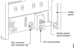
Step 4 Plug each AC power cord into a single-phase wall outlet rated for a nominal voltage between 200 and 240 VAC. Each outlet must also be capable of supplying up to 16 Amps (13 Amps in the UK, where the plug has a built-in, 13 Amp fuse). In North America, the building circuit should be protected with a 20 Amp circuit breaker.
Step 5 The ground (green) wire of each AC power cord is connected to the IGX for safety ground. Make sure each AC receptacle in the building is grounded.
Step 6 Provide an AC power strip with at least four outlets. Place it near the IGX node to supply optional modems, CSU, DSUs, or test equipment. Be sure to connect this power strip to an AC source voltage that is standard for the region (for example, 115 VAC in North America).
This section explains how to attach power to the pre-installed PEMs in redundant and non-redundant configurations. Systems that use a DC power source have up to four possible configurations, as follows:
Wiring is connected from one or two -48 VDC power sources to one or two DC PEMs on each shelf. Refer to the following figures for the possible DC PEM arrangements:
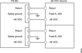
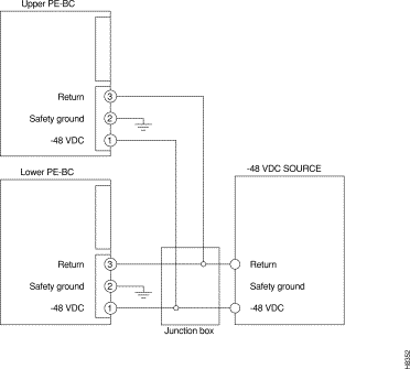
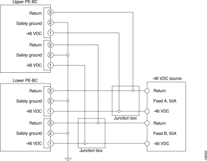
Installing DC power consists of attaching the three wires from the DC power source to a removable wiring block and plugging that block into the connector on the PEM. The PEM is plugged into the PE-BC. Figure 3-24 is a view of a PE-BC out of the card cage with the PEM wired up and plugged into the PE-BC. Figure 3-24 shows a PE-BC with one PEM in place and the other connection not used. An unused connection has a blank cover plate.

To make a DC power connection:
| Warning
Remember that this is a positive ground system. Ensure that polarity of the DC input wiring is correct. Under certain conditions, connections with reversed polarity may trip the primary circuit breaker and/or damage the equipment. Make sure the circuit breaker is in the OFF position. |
Step 1 For both rack-mount and stand-alone systems, the cable guard (located at the right edge of the chassis) remains off until the system is ready to power up. If the system is a stand-alone, remove the cable guard by loosening the captive screw at its base then swinging it away from the chassis (do this latter movement holding the top of the cable guard in place while moving the bottom of it away from the chassis).
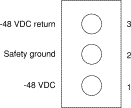
Step 2 Insert and secure the stripped ends of the wire in the wiring block according to the scheme in Figure 3-25 and Figure 3-26. Figure 3-26 illustrates the polarity of each connection on the pluggable terminal block. The numbers start with 1 at the bottom and go up to 3. The connection at the bottom is for the -48 VDC wire. The middle wire is Safety Ground. The connection at the top is for the positive return wire (for the -48 VDC). Figure 3-26 shows the assembly with an example wire and the screw that secures it in the pluggable wire block.
Step 3 Attach the pluggable terminal block to the receptacle on the PEM.
Step 4 Loop the DC wiring through the strain relief clamp.
| Warning For personal safety, the green or green/yellow wire must connect to safety (earth) ground at the equipment and the supply side of the DC wiring. |
Step 5 Connect the DC input wiring to a DC source capable of supplying 25 Amps per shelf. The -48 VDC power source in the building should have a 25 A DC circuit breaker for each shelf in an IGX 16 and a 50 Amp circuit breaker for each shelf in an IGX 32. The building's wiring should include an easily accessible disconnect device. Make sure the ground wire connects to a reliable building (earth) ground.

Step 6 Leave the cable guard off until power is on. See the "Initial Startup of the IGX" section.
Step 7 Before turning the system power on, check the supply voltage. Use the screws at positions 1 and 3 on the pluggable terminal block as a convenient measuring point. Also, check the impedance between the safety ground (screw at location 2 on the pluggable terminal block) and the chassis. It should be close to 0.
This section describes how to make IGX signal connections.
The following trunk connections are supported:
The following service module connections are supported:
T1 trunk connections use the NTM front card and the BC-T1 back card. Japanese Y1 connections use the NTM front card and the BC-Y1 back card. The procedure for making Y1 connections is the same as for T1 connections described below.
Make the T1 connections as follows:
Step 1 Bring each T1 cable through the opening at the bottom of the cabinet (if applicable) and up the back of the unit.
Step 2 Use the cable management feature to help route the cables.
The T1 lines are attached to DB-15, Sub miniature, 15-pin connectors on the BC-T1 cards.
Step 1 Connect the trunks to the connectors on the BC-T1 back cards that are part of NTM/BC-T1 card sets. Figure 3-27 illustrates a BC-T1 face plate.
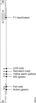
The back slot line numbers correspond to the back slot number in which the BC-T1 card resides. Record the back slot number of each line. These number are necessary for configuring the system after installation is complete.
E1 trunk connections use the NTM front card and the BC-E1 back card. Subrate E1 connections use the NTM front card and the BC-SR back card. The E1 Trunk Interface Card BC-E1 (Figure 3-28) contains the E1 trunk connector (G.703 Input/Output) that is located at the top of the back card. There are four 75 ohm BNCs on the BC-E1 faceplate.
| Caution Connect only equipment that complies with BS6301 to ports and monitor jacks. |
Make the E1 connections as follows:
Step 1 Bring each E1 BNC patch cable (or 15-pin cable) through the opening at the bottom of the cabinet (if applicable) and up the back of the unit.
Step 2 Connect the trunks to connectors on the BC-E1 back card that are part of a NTM/BC-E1 card set.
Step 3 Use the cable management feature to help route the cables.
The back slot line numbers correspond to the back slot number in which the BC-E1 card resides. Record the back slot number of each line. These number are necessary for configuring the system after installation is complete.
AIT cables connect the BTM front card to a node at the back card.
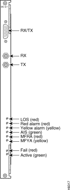
The AIT back card has female BNC connectors for transmit and receive trunk connections. Use 75-ohm coax cable RG-59 B/U for short runs, AT&T 734A for longer runs. There are two per T3/E3 trunk (XMT and RCV). Cabling requirements appear in Appendix C. Figure 3-29 shows an AIT-T3 faceplate with connections and LED indicators.

The ALM (ATM Line Module) and UAI-1T3-BC (Universal ATM Interface T3 Back Card) set provide an interface for ATM traffic between user equipment and the node. This section reviews the characteristics and describes how to set up this feature. For a description of this circuit line card set, refer to the ALM description in the chapter titled "Hardware Description." The following characteristics apply to ALM:
After the ALM card has been activated, take the following steps:
Step 1 Using the cnfpln command:
Step 2 Using addcon involves neither the standard ATM class nor many of the parameters for ATM connections on a trunk. Neither cell rate policing nor ForeSight is involved. Parameter specification consists of:
After configuring the line with cnfpln, use dspplns to check configuration. The system prepends the letter "u" to the connection type to show that the connection is on an ALM. For example, "ucbr" is an ATM CBR connection on an ALM. During network operation, the dspplnutl command shows the amount of traffic and percent of utilization on the line.
The CVM front card operates with either a BC-T1, BC-E1, or BC-J1 back card to provide channelized voice and data connections. Back card cabling is identical to that of trunk T1, E1 and J1 connections, respectively. Refer to "Making T1 or Y1 Trunk Connections" section and "Making E1 or Subrate Trunk Connections" section for details. For information on CVM support of Dynamic Circuit Switching (DNS), refer to the DNS Installation and Operation manuals.
The next section describes a specialized version of data transmission service called TDM Transport. It applies to older, non-StrataCom WANs.
This section describes how to plan for the Time Division Multiplexing Transport (TDM Transport) feature. Note that TDM Transport requires Rev. C firmware on all connected CVMs or CDPs that use this feature. Refer to the section "The TDM Transport Feature " in Chapter 1, for a description of Rev. C firmware features and limitations. Refer to the Command Reference for a description of the command parameters in related commands.
Before adding a bundled connection under TDM Transport, consider the following:
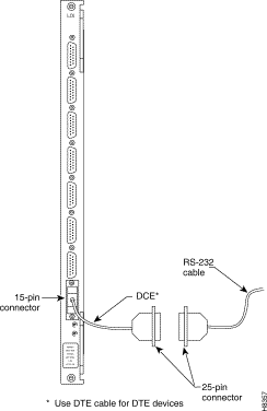
The Low-Speed Data Module (LDM) and High-Speed Data Module (HDM) front cards operate with a variety of data interface back cards to provide data connections. The LDM uses an LDI card for an interface. The HDM uses an SDI card.
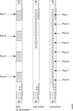
The LDM front card uses the 4-port or 8-port version of the LDI back card for RS-232C/D (V.24) connections or with the LDI4/DDS back card for DDS (Digital Data Service) connections. The data connection ports are labeled PORT 1 through PORT 4 or PORT 1 through PORT 8. See Figure 3-30 for illustrations of these back cards. For instructions on configuring an LDI port for DTE or DCE mode, refer to the forthcoming section titled Configuring the Mode of an LDI Port.
The HDM front card works with an SDI back card. Four types of SDIs are available. These are the V.35, RS-449/422, RS-232D, and RS-232C (V.24)—X.21 requires RS-449 plus an adapter cable. Each type of SDI has four connection ports, which are labelled PORT 1 through PORT 4. An example SDI card appears in Figure 3-30.
When attaching A data line to A SDI, LDI, or DDS port, use the shortest reasonable length of cable to connect each port.
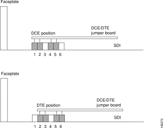
The factory-set, default mode of an SDI port is DCE. (Although this is the default, verify it before starting up the system. See Step 1.) For the two modes, the occupied rows on the back card jumper connector are as follows:
To change the mode on a port to DTE, position the jumper card for that port as follows:
| Caution To prevent damage to the SDI cards, wear a wrist strap and clip the strap to the enclosure. |
Step 1 At the back of the IGX, remove the SDI card, as follows:
Step 2 Move the jumper card one row of pins away from the SDI faceplate (Figure 3-31). For DTE mode, the jumper card should occupy rows 2, 3, 5, and 6.
If a port is in DTE mode and needs to be changed to DCE, plug the jumper card into the connector receptacle pin rows closest to the SDI faceplate (Figure 3-31). These rows are 1, 2, 4, and 5.
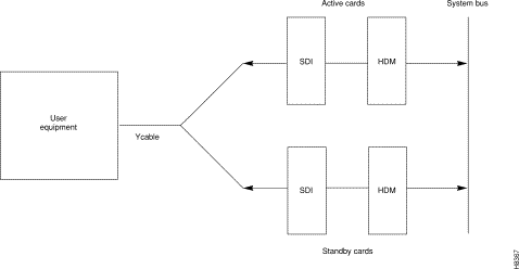
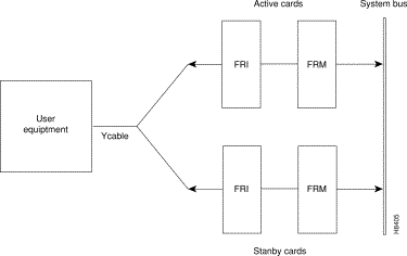
Optional redundancy for HDM and LDM cards can be provided with a second front and back card set and a Y-cable connection on each port to the customer data equipment, as Figure 3-32 shows. (The arrangement for HDM and LDM card groups is the same.)
Each port on an LDI card uses an adapter cable. For a list of LDI adapter cables, refer to Appendix C, "Cabling Summary." Each cable does the following:
See Figure 3-33 for an example. In Figure 3-33, the adapter cable makes the port a DCE port. Circuits on the card check identifying pins on the cables and configure the ports as DTE or DCE.
Four types of frame relay interfaces are available:
The T1 line terminates on the FRI-T1 card to a DB15 sub miniature connector. The FRI card has a female connector. A BNC type connector is used for the unbalanced connection.
The FRI-E1 card provides for a 75-ohm unbalanced coax line termination or a balanced 120-ohm twisted pair termination. A DB15 connector is used for the balanced connection. The FRI card has a female connector.
The V.35 connection uses a standard 34-pin female MRAC type connector with a standard V.35 cable.
The FRI-X.21 has female DB15 sub-miniature connectors.
The cabling requirements for the different frame relay interfaces appear in Appendix C.
Optional redundancy on a frame relay port can be provided with a second FRM/FRI card set and a Y-cable connection on each port to the customer data equipment. The forthcoming section titled "Setting Up a Frame Relay Port ", includes steps for setting up card redundancy. The card redundancy kit for this purpose contains a second FRM/FRI card set, four Y-cables to interconnect the two card sets to the customer connection, and a 200-ohm DCE/DTE jumper card for the installed FRI. In the case of either a V.35 or X.21 interface, the DCE/DTE daughter card on the FRI must be changed when a non-redundant card set is changed to a redundant card set. Only the model D of the V.35 or X.21 back cards use the daughter card.
Y-cable redundancy is not possible between inconsistent back card types, such as FRI T1/E1 to FRI V.35. The screen display for the dspyred command shows a back card conflict with a configured interface in reverse video. (Refer also to the descriptions of the upcln and upfrport commands in the Command Reference.) Inserting a front card that does not support the number of upped ports is flagged by displaying the front card in reverse video on the Y Cable Redundancy Screen.
After the hardware is installed, the node must be reconfigured to indicate that the slot is equipped with redundancy. Use the Add Y Redundancy (addyred) command to do this. Refer to the Command Reference for more information on the commands addyred, delyred, dspyred, and ptyred.
The four ports on the FRI-X.25 are equipped with female DB15 sub miniature connectors. The four ports on the FRI-V.35 are equipped with female, 34-pin MRAC connectors. Each port may be configured as a DCE or as a DTE by selecting the position of a jumper card mounted on the FRI.
| Warning Only qualified personnel should open the cabinet door. |
| Caution To prevent damage to the FRI cards, ground yourself before handling IGX cards by clipping a grounding strap to your wrist, and clipping the wrist strap lead to the enclosure. |
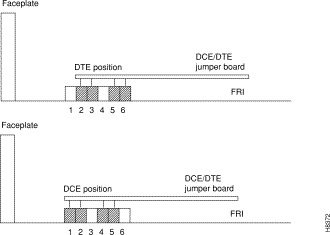
The factory-set, default mode of an FRI port is DCE. (Although this is the default, verify it before starting up the system. See step 1, below.) For the two modes, the rows on the back card jumper connector that are occupied when the jumper card is in place are as follows:
If an interface mode need changing, reposition the jumper board for the port as follows:
Step 1 At the back of the IGX cabinet, identify the slot number of the FRI card.
Step 2 Loosen the captive mounting screws on both ends of the faceplate.
Step 3 Operate the card extractor levers and slide the card out.
Step 4 For each port that is being changed to DTE, move the jumper board one row of pins away from the FRI faceplate (Figure 3-34). For DTE mode, the jumper board should occupy rows 2, 3, 5, and 6.
If a port is in DTE mode and needs to be changed to DCE, plug the jumper board into the connector receptacle pin rows closest to the FRI faceplate (Figure 3-34). These rows are 1, 2, 4, and 5.
Step 5 Re-insert the FRI card and gently slide it in all the way to the rear of the slot.
Step 6 Screw in the mounting screws.
This section describes the steps for setting up a frame relay port after hardware installation and system startup. Setting up a frame relay port is done at the IGX control terminal or StrataView Plus workstation. For details on each command in this section, refer to the Command Reference.
Step 1 Verify that the nodes at each end of the connection have the correct FRI back card and FRM front card. Use the Display Cards (dspcds) command. The output of this command shows the shelf and slot of each card. Make a note of each position.
Step 2 Check the port types (DCE or DTE) using the Display Frame Relay Port (dspfrport) command for the FRI/FRM slot as located in the previous step.
Step 3 If a redundant card is used, configure the card pair for redundancy by using the Add Y-Cable Redundancy (addyred) command for this slot. See Figure 3-35 for the cabling arrangement for Y-cable redundancy.
Step 4 Configure the port for speed, clocking, LMI type, and so on, by either configuring the parameters with the Configure Frame Relay Port (cnffrport) command or using the default parameters. Set the Port ID to the DLCI assigned to this end of the connection (required if using bundled connections, optional otherwise).
Step 5 Prior to activating a logical port on either a T1 or E1 line, the port must be added (addfrport). (Because V.35 and X.21 connections are not channelized, adding logical ports on these interfaces is not necessary.)
Step 6 Activate the port using the Up Frame Relay Port (upfrport) command.
Step 7 Specify a frame relay class. Two approaches are available. A variety of pre-specified classes are available, or the Configure Frame Relay Class (cnffrcls) command can be used to specify the class. To see the pre-specified classes, use the Display Frame Relay Classes (dspfrcls) command then select an appropriate class for the connection.
Step 8 If a connection was not added in the last step through the use of a pre-specified frame relay class, add the connection to the network by using the Add Connection (addcon) command. Enter the slot address and DLCI for each end of the connection.
Step 9 Configure the connection parameters using the Configure Frame Relay Connection (cnffrcon) command, or use the default values. If ForeSight is a purchased option, enable it now.
Step 10 Setting the channel priority using the Configure Channel Priority (cnfchpri) command is an option at this time. Typically, the priority that the system automatically sets is sufficient.
When a port has multiple PVCs, optional bundling or grouping the connections is available. Bundling facilitates meshing. Grouping helps conserve system resources such as device codes and logical connections in networks, which need a high level of standardization.
Step 11 For grouping connections, first establish a connection group with the Add Connection Group (addcongrp) command. The Display Connection Group (dspcongrp) command displays existing groups.
Step 12 Group connections using the Group Connection (grpcon) command.
Step 13 Connections are bundled during parameter specification in the Add Connection (addcon) command for frame relay: when the Return key is pressed without a DLCI during port specification, prompts appear for bundling connections. Refer to the Frame Relay Connections chapter in the Command Reference.
The types of FastPAD interfaces are T1, E1, V.35, and X.21.
FastPAD connections use the FTM front card and an FPC back card. The back card versions are FPC T1, FPC E1, FPC V.35, and FPC X.21.
The T1 card has a DB15 for RX/TX. The E1 connections are the same except for additional BNC connectors for unbalanced connections and BNC connectors for RX/TX MONITOR.
A V.35 connection uses a standard 34-pin female MRAC-type connector with a standard V.35 cable. The FPC-X.21 has female DB15 sub miniature connectors.
The cabling requirements are the same as for the corresponding frame relay interface and are detailed in Appendix C.
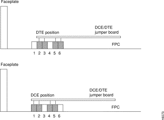
Each of the four ports on the FPC V.35 and X.21 versions may be configured as a DCE or as a DTE by selecting the position of a jumper card on the FPC. These ports are factory-configured as DCE interfaces.
| Warning Only authorized personnel should open the cabinet. |
| Caution To prevent damage to the FTM and FPC, put on a ground strap and clip the wrist strap lead to the enclosure. |
To change a port's interface configuration on the FPC V.35 or FPC X.21, reposition the jumper card for the port as follows:
Step 1 At the back of the IGX cabinet, identify the slot where the FPC card resides.
Step 2 Loosen the captive phillips screws at both ends of the faceplate.
Step 3 Rotate the card extractor levers and slide the card out.
Step 4 For each port that is being changed to DTE, move the jumper card to the row of connector pin that is farther away from the FPC faceplate. Figure 3-36 shows positions for both DTE and DCE.
Step 5 To change a port to DCE, plug the jumper card into the row of connector pins that is closer to the FPC faceplate. See Figure 3-36.
Step 6 Re-insert the FPC card and gently slide it in all the way to the rear of the slot.
Step 7 Screw in the mounting screws.
To install an ARM card set, proceed as follows:
Step 1 At the back of the IGX, identify the slot where the ARI card is to reside.
Step 2 Install the ARM in the front slot and use the card extractors to help secure card.
Step 3 Install the ARI in the corresponding back slot. Use the extractor handles to help secure the card then tighten the captive screws by hand.
Step 4 Note that the FAIL LED on the ARM is off. The ACTIVE LED is also off.
Step 5 Attach a 22 or 24-gauge cable with the appropriate number of pairs to a male DB37 connector at one end. Typically, a 12-pair cable is adequate. Connect this cable to the DB37 connector on the ARI and tighten the captive screws.
Also see the section "Initial Startup of the IGX," when the system is ready for power.
The steps that follow show how to set up an ARM card set after the physical installation is complete. This is done from the IGX control terminal or StrataView Plus workstation. For details on each command used, refer to the Command Reference.
Step 1 Use the dspcds command to verify that the node is equipped with the proper ARM front card and ARI back card.
Step 2 From a control terminal or a StrataView Plus NMS workstation, vt to the node and enter the addalmslot command followed by the slot number where the ARM is located. This will activate the alarm reporting from the card.
Step 3 Observe that the ACTIVE LED on the ARM card is on.
Step 4 Testing the operation of the alarm outputs involves creating an alarm and noting the corresponding alarm output. This test is easy on a node that is not connected to the network but not on a node that is part of a fully operational network. The best time to create a major alarm is during a low traffic period. If this is performed, proceed with step 5. Otherwise, stop here.
Step 5 Create an alarm by disconnecting a trunk cable from the connector on a back card.
Step 6 Observe that there is a MAJOR LED lit on the front of the ARM.
Step 7 Using a voltage/ohm meter (VOM), make sure continuity exists between pins 16 and 17 and between pins 35 and 36 at the DB37 connector on the ARI card.
Step 8 Reconnect the cable that was disconnected in step 5.
Step 9 With the VOM, check that the reading between pins 16 and 17 and pins 35 and 36 are open and the MAJOR LED is not on.
Alarm output connections go to the DB37 connector on the ARI. The pin assignments with the alarm signal names are in the table that follows (see also Appendix C).
| Pin # | Alarm Type | Alarm Name | Alarm Description |
|---|---|---|---|
1 | both | CHASSIS | Protective ground |
3 | Network | NWMAJA | Major—normally open contact |
22 | Network |
| Major—normally closed contact |
4 | Network | NWMAJC | Major—common contact |
10 | Node | MNVISA | Minor Visual—normally open contact |
11 | Node |
| Minor Visual—normally closed contact |
12 | Node | MNVISC | Minor Visual—common contact |
16 | Node | MJAUDC | Major Audible—common contact |
17 | Node | MJAUDA | Major Audible—normally open contact |
23 | Network | NWMINA | Minor—normally open contact |
24 | Network |
| Minor—normally closed contact |
25 | Network | NWMINC | Minor—common contact |
29 | Node | NWAUDA | Minor Audible—normally open contact |
30 | Node |
| Minor Audible—normally closed contact |
31 | Node | NWAUDC | Minor Audible—common contact |
35 | Node | MJVISC | Major Visual—common contact |
36 | Node | MJVISA | Major Visual—normally open contact |
Table 3-3 shows the unassigned connector pins.
| Pin # | Alarm Type | Alarm Description |
|---|---|---|
7 | Relay 2 | common contact |
8 | Relay 2 | normally closed contact |
9 | Relay 2 | normally open contact |
26 | Relay 4 | common contact |
27 | Relay 4 | normally closed contact |
28 | Relay 4 | normally open contact |
The DB15 connector labeled Ext Clocks on the faceplate of the SCM connects two external sources for a high-stability clock (primary and redundant). These inputs are 1.544 MHz for T1 systems and 2.048 MHz for CEPT systems. In addition, one of the trunk or circuit line inputs may also serve as a source of timing for the node. If no clock source is selected, the clock source is the internal IGX clock.
Two separate clock inputs exist. The primary clock source is A, and the secondary clock source is B. One or both of these can be either 1.544 Mbps or 2.048 Mbps. The connector pinouts are described in Appendix C.
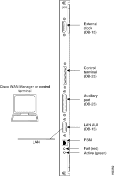
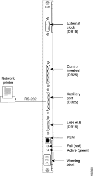
A network must have at least one control terminal (or StrataView Plus workstation if you wish to collect statistics) attached, along with a network printer for printing out the status of the system. The SCM has three ports for attaching peripherals to an IGX. These ports are CONTROL TERMINAL, LAN AUI, and AUX PORT.
For StrataCom ISC to perform remote troubleshooting, a modem must connect to the network. This is a requirement for all StrataCom service plans. The following sections provide procedures for attaching peripherals to the IGX. Be sure to read the manufacturers' literature to ensure that the equipment is ready before attempting to connect it to the IGX.
To use network management, at least one node in a StrataCom network running Release 7.2 software must have a StrataView Plus workstation connected. The workstation connects to the AUI Ethernet LAN port on the SCM.
The StrataView Plus workstation may be used to configure and maintain all nodes in a network. For instructions on using the StrataView Plus workstation, see the StrataView Plus Operations Manual.
If only a single NMS station is to be connected and the network is relatively small, a serial RS232 port, the CONTROL TERMINAL port, may be used.
Appendix B lists the control terminals supported by the IGX and the configuration settings. Appendix C lists the pin assign-ments for the IGX control terminal port.
Attach the control terminal to the SCM as follows (see Figure 3-37).
Step 1 From the back of the cabinet, run the control terminal RS-232/V.24 cable through the opening at the bottom and up to the SCM card in back slot 1.
Step 2 Locate the CONTROL TERMINAL connector on the SCM and attach the control terminal RS-232/V.24 cable to it.
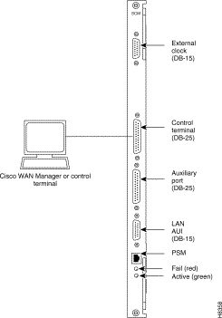
Step 3 Tighten the RS-232 connector screws to firmly attach the cable to the CONTROL TERMINAL connector.
Step 4 Plug the control terminal power cord into the appropriate wall receptacle.
Step 5 Set the port function for VT100 (#5) using the cnftermfunc command.
Step 6 Make sure the AUXILIARY port and the terminal are set to the same baud rate and check the other communication parameters using the cnfterm command.
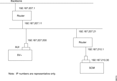
If the network is large or extensive network statistics are needed, an Ethernet port (LAN port) should be used. Larger networks produce a greater flow of statistics data between the node and the StrataView Plus workstation, so a higher speed Ethernet port is suitable. Figure 3-38 illustrates this connection. Accessing a node over an Internet connection requires the operator to use cnflan to enter the Internet Protocol (IP) address, IP subnet mask, TCP service port, and gateway IP address.
Step 1 Contact a System Administrator to obtain IP addresses for the workstation and for the IGX node.
Step 2 Normally, the System Administrator updates the NIS database, as applicable (if an NIS is used), and adds the IP addresses for the workstation and node to the NIS database. Refer to the StrataView Plus Operations Manual for instructions on configuring the StrataView Plus workstation.
The addresses shown are examples. Use the addresses obtained from the System Administrator. (This example is for a workstation named "hedgehog" at address 192.187.207.200. It also assumes that the IGX node LAN port for node "sanfran" has been assigned an IP address of 192.187.210.30 and a hostname of "sanfran.")
192.187.207.200 hedgehog
192.187.210.30 sanfran
Step 3 Configure the LAN port on the IGX node using a dumb terminal or an RS-232 connection via the workstation (using the vt command, as applicable) to enter the appropriate cnflan parameters.
The cnflan command configures the node's communication parameters so that the node can communicate with a StrataView Plus terminal over an Ethernet LAN using the TCP/IP protocol. The parameters contain address information about the Ethernet TCP/IP network that is used to connect the StrataView Plus workstation to an IGX node. The values used must conform to those of the network and should be supplied by the Ethernet network administrator.
The cnflan command has the following parameters:
Figure 3-39 shows a cnflan screen. The active IP address for the workstation has been entered as the IP address selected previously for the node, 192.187.207.21. The IP Subnet mask is entered as 255.255.255.0 for a Class C LAN network. The TCP service port is entered as 5120. Since the workstation and node are on different networks in this example, a gateway address of 192.187.207.1 has been entered. If the workstation and node are both on the same network, no gateway address is needed. The "Maximum LAN Transmit Unit" and "Ethernet Address" parameters are not configurable by the cnflan command. The "Ethernet Address" is a hardware address ("burned into the NPM card") that is unique to each NPM card.
D2.cb1         LAN   StrataCom       IGX 16    8.2     Feb. 27 1996 14:23 PST


Active IP Address:                     192.187.207.21
IP Subnet Mask:                        255.255.255.0
TCP Service Port:                      5130
Default Gateway IP Address:            192.187.207.1

Maximum LAN Transmit Unit:             1500
Ethernet Address:                      00.55.43.00.04.55

Control Socket - Ready
Base Socket Descriptor - 1

Socket Closed


Last Command: cnflan


Next Command:
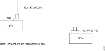
Step 1 Connect the StrataView Plus workstation and the IGX node to a LAN network. Examples are shown in Figure 3-40 and Figure 3-41. The LAN port on the IGX node provides a DB-15 connector that can be connected to a Y-cable which in turn is connected to an AUI as shown in Figure 3-41.
Step 2 To test that a LAN connection to the IGX LAN port is good, an example hostname of "sanfran" entered in the config.sv file, enter the following at the StrataView Plus workstation:
ping sanfran
Step 3 Once the workstation and IGX node interface has been set up, StrataView Plus can be started. Figure 3-42 shows the dsplan screen after StrataView Plus has been started and the communication sockets are active.
D2.cb1         LAN   StrataCom       IGX 16    8.2       Feb. 27 1996 14:27 PST


Active IP Address:                     192.187.207.21
IP Subnet Mask:                        255.255.255.0
TCP Service Port:                      5130
Default Gateway IP Address:            192.187.207.1

Maximum LAN Transmit Unit:             1500
Ethernet Address:                      00.55.43.00.04.55

Control Socket - Ready
Base Socket Descriptor - 1

Open Socket Descriptor - 2


Last Command: dsplan


Next Command:
| Caution Before switching on the StrataView Plus workstation, refer to the StrataView Plus Operations Guide. |
Step 4 Switch on the control terminal (or StrataView Plus workstation). Adjust the terminal's configuration, if necessary, to match the default settings of the control terminal port in the IGX. See Appendix B, "Peripherals Specifications," for the required settings. See the StrataView Plus Operations Guide for settings and operating instructions for the workstations.
When a network management station has more than one serial port, ports may connect to different networks. When the number of workstation serial ports is less than the number of networks to be managed, a terminal server is necessary to obtain a communications link to the separate networks. This subject is covered in the StrataView Plus Installation Guide.
At least one node in the network should have an attached printer. The printer displays information about network operation. It can be configured to print maintenance information on a regular basis, and it can print specific diagnostic information when necessary. Instructions on using the printer for this purpose are in the Command Reference.
To attach the printer to the AUX PORT on the SCM:
Step 1 Check the printer RS-232/V.24 cabling pinout and, if required, adjust the DIP switches to the settings indicated for the type of printer to be connected to the IGX. See Appendix B for RS-232/V.24 cable pinout and DIP switch settings.
Step 2 At the back of the cabinet, run the printer RS-232/V.24 cable through the opening at the bottom and up to the SCM card in back slot 1.
Step 3 Connect the printer RS-232/V.24 cable to the SCM's AUX PORT. See Figure 3-43.
Step 4 Tighten the connector screws on the cable at the AUX PORT connector.
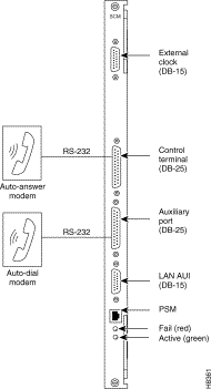
Two modems may be connected to the IGX in order to provide access for remote troubleshooting and for remote alarm logging (see Figure 3-44). Each connection between the SCM and a modem requires a special cable and setup procedure. Refer to Appendix B for instructions on connecting and setting up the modems.
The modem that is used to provide access for remote troubleshooting from the StrataCom International Support Center (ISC) office (ISC-to-IGX modem) is connected to CONTROL TERMINAL port on the SCM. Typically, the modem connects to the telephone wall jack with a direct-dial line.
The modem that provides remote alarm logging (IGX-to-ISC modem) connects to the AUX PORT on the SCM. This modem connects to a wall jack using a standard telephone line.
This section describes checkout procedures to follow after the hardware is in place and ready to receive power. The "IGX Configuration Summary "section summarizes the steps and lists the commands for brining up the system.
Before using the IGX, make sure the following procedures have been done:
Step 1 If the IGX uses AC power, make sure the IGX is connected to the correct AC receptacle. For a DC-powered unit, make sure it connects to the correct, dedicated DC source.
Step 2 Check the record for the correct switch status for switch W6 on the SCM. See the recommendation in the section "Readying the Cards." If the switch position was not previously verified, do so now. W6 sits above component U7P on the SCM. To indicate to the SCM that the system is an IGX 32, remove the jumper. To indicate to the SCM that the system is an IGX 16, leave the jumper on the card.
Step 3 The full complement of cards for the specific node are mounted in the correct slots, correctly seated, and locked.
Step 4 The T1 connections are attached to the appropriate BC-T1 faceplate.
Step 5 The E1 connections are attached to the appropriate BC-E1 faceplate.
Step 6 The Fractional E1 or T1 connections are attached to the BC-E1 or BC-T1 card connector, if the IGX is used to provide Fractional E1 or T1 service.
Step 7 The Subrate connections are attached to the BC-SR card connector if the IGX is used to provide Subrate E1 or T1 service.
Step 8 The data connections are attached to the appropriate SDI/LDI cards.
Step 9 The Frame Relay User Device Connections are attached to the appropriate FPC card connectors.
Step 10 A control terminal is connected to the CONTROL TERMINAL port on the SCM in back slot 1, or a StrataView Plus workstation is plugged into the AUI port, and the power cord plugged into the appropriate AC receptacle.
Step 11 If specified, a printer connects to the AUX PORT on the SCM in back slot 1, and the power cord is plugged into the appropriate AC receptacle.
Step 12 If specified, one or more modems connect to the CONTROL TERMINAL port or AUX PORT, as applicable, on the SCM in back slot 1, and any modem power cords plug into the appropriate AC receptacle.
Step 13 At the back of the unit, turn the circuit breakers to the ON position. In a system using a DC source, attach the cable guard (AC should already have the cable guard in place). After initial powerup, DC systems can be switched off and on either at the PEM or at the building site's resident circuit breaker. Use the building's DC circuit breaker only if all cables are clearly marked; if the building's dedicated circuit breaker has an actual switch and not just a fuse; and if controlling power at the building's circuit breaker actually provides an advantage over removing the cable guard.
Step 14 Observe that, after the IGX node switches on, the cards go through a series of initial diagnostic self-tests.
Step 15 If an alarm exists for a T1 or an E1 line that is physically connected to the IGX, try reconnecting the line to make sure there is a good physical connection. If the alarm condition continues, a valid T1 or E1 problem may exist.
The IGX software contains a group of diagnostic tests that run on the system's hardware at power-up. The startup diagnostic either passes or fails the NPM(s). The test result is displayed on the control terminal screen as pass or fail (Figure 3-45 or Figure 3-46).
**************************************************************************************
Release 7 Boot power up diagnostics starting.

68000 Internal Registers test passed.
68000 clock test passed.
Static RAM test passed.
TDM memory test passed.
Fast RAM test passed.
BRAM test passed.
Dynamic RAM test from Hex Address 400000 to Hex Address 9FFFFF

Release 7 Power up diagnostics complete.
********************************************************************************
**************************************************************************************R
elease 7 Boot power up diagnostics starting.

68000 Internal Registers test passed.
68000 clock test passed.
Static RAM test passed.
TDM memory test passed.
Fast RAM test passed.
BRAM test failed.
Remove and reinsert this NPM to see if it fails again.
********************************************************************************
If an NPM fails the power-up diagnostic, it does not boot See Figure 3-46. When this happens, do the following:
Step 1 Remove the failed NPM from its slot.
Step 2 Install the NPM in the same slot again.
Step 3 Wait for the power-up diagnostic to run.
Step 4 If the NPM fails the power-up diagnostics again, replace it with an NPM that is known to be good. For card replacement procedures, refer to Chapter 5.
IGX software includes internal diagnostics that periodically test each card's performance. These self-test diagnostics automatically start and run in background. They do not disrupt normal traffic. If a failure occurs during self test, the faceplate FAIL LED lights up, and the operator can view the status at the control terminal by executing the dspcd command.
The status of a card failure remains until cleared. A card failure is cleared by the Reset Card (resetcd) command. The two types of resets are failure and hardware. The reset failure clears the event log of any failure detected by the card self-test but does not disrupt operation of the card. A reset of the card firmware is done by specifying a hardware reset. This reboots the firmware and momentarily disables the card. If a redundant card is available, the hardware reset causes a switch over to the standby card.
Check the status lights on the system unit cards. Table 3-4 shows the normal status of each light. Table 3-4 reflects n+1 redun-dancy for NTM and CVM cards.
| Card | Active Status | Standby Status1 | Alarms |
|---|---|---|---|
NPM | 1 | 1 | - |
CVM | - | - | - |
NTM | - | all | - |
BC-T1/E1 | - | all | - |
BC-SR (Subrate) | - | all | - |
AIT-T3/E3 | - | all | - |
HDM/LDM | - | all | - |
SDI/LDI | - | all | - |
FRM | - | all | - |
SCM | 1 | 0 | - |
BTM | - | all |
|
ARM | 1 | -- | - |
Power Supplies | All | - | - |
| 1Standby status is indicated by no lights on. |
The way to verify the correct power supply voltages is the DC Okay and AC Okay LEDs on each power supply and the dsppwr command. If any LED is off, a problem exists in relation to that supply. Power supplies are not field-adjustable. If a power supply voltage is out of tolerance, replace the supply with one known to be within tolerance. Refer to the AC power supply replacement procedure in Chapter 5, "Repair and Replacement."
This section outlines the steps and specifies the commands for configuring a network. For a complete description of each command, refer to the Command Reference or Superuser Command Reference.
Configuration and management of the IGX is very similar to that of StrataCom's IPX and BPX systems. Configuration is done via commands entered at the control terminal. Management of the IGX is done via the StrataView Plus Network Management Station.
For IGX configuration, the control terminal can have system access through a local control port (over an RS-232 or Ethernet TCP/IP link) or from a control terminal screen on a StrataView Plus Network Management Station (NMS). Remote control terminal access is possible using a Virtual Terminal (vt) command if the node has been configured with a name (cnfname) and at least one trunk to the network has been established.
The basic tasks to configure an IGX are as follows:
Two approaches are available for establishing a frame relay-to-ATM interworking connection in a tiered network (see the System Manual for a description of tiered networks). The simplest approach is to use the Connection Manager in StrataView Plus. When the connection to an FRSM on an AXIS interface shelf is specified, the correct end-to-end connection type is established. This connection type is either atfr (ATM-to-frame relay interworking) or atfst (ATM-to-frame relay interworking with ForeSight). The other approach is to use the command line interface on the IGX 8 or other routing node to execute addcon and related commands (such as cnfcon) to establish the connection between routing nodes. A network interworking connection requires that each connection segment be specified. (Establishing the connection between the FRSM on the AXIS shelf and the BPX requires execution of the addchan command.)
You can monitor, manage, and troubleshoot the IGX using the StrataView Plus Network Management Station. Issue commands to an IGX node through the Node Administration window. Display and monitor the network's topology using the Network Overview and Network Topology windows. Alarms are reported and logged into the Event Log window. Statistics are collected and displayed through the SV+ Statistics window.
![]()
![]()
![]()
![]()
![]()
![]()
![]()
![]()
Posted: Mon Sep 16 17:57:19 PDT 2002
All contents are Copyright © 1992--2002 Cisco Systems, Inc. All rights reserved.
Important Notices and Privacy Statement.