|
|

This chapter covers the tasks of replacing a single card, a power supply, or a complete node.
The requirements for moving a node depend on the distance involved. In all cases however, the node must be disconnected from the network by:
The remainder of the task is the physical move of the unit. Use the pallet and box that came with the original packing to move the node a long distance. For shorter moves of a stand-alone unit, screw the feet up into the unit to expose the wheels then roll the unit.
 | Caution When moving a STRATM cabinet, do not push the cabinet at its sides. Instead, grip the cabinet at the front or back edges to maneuver it to the new location. |
This section describes how to perform a hot replacement of a front card. Read the following list before proceeding with front card replacement:
To replace a card with the power on:
Step 1 If necessary, delete relevant connection with the delcon command.
Step 2 Loosen the two phillips captive screws in the faceplate.
Step 3 Operate the extractor handles to disconnect the card from the backplane.
Step 4 Pull the card out of the card cage.
 | Warning Correct alignment between connector pins and receptacles is extremely important. Before inserting a card, make sure all backplane pins are straight. Make sure the connectors on the card and backplane are aligned. Insert card gently. |
Step 5 Installing a front card requires the card to be inserted into the card track and pushed firmly but gently into the connector on the back card (or the backplane connector if the card is an NPM).
Step 6 Hold the extractor handles in the open position until they contact the shelf supports and then rotate them into the closed position.
Step 7 Tighten the captive screws on the card's faceplate just enough to secure the card.
This section describes how to remove and replace a back card such as the SCM.
Step 1 Visually inspect the replacement back card to verify it is in good working order.
Step 2 Identify and mark any cable locations before removing cables from a back card.
Step 3 Loosen the captive screws on the top and bottom of the faceplate of the card.
Step 4 Operate the extractor levers then slide the card out of the cabinet.
Step 5 Before installing a replacement back card, make sure that the pins are straight.
 | Warning Correct alignment between connector pins and receptacles is extremely important. Before inserting a card, make sure the pins on the front card are straight. Make sure the connectors on the card and the backplane align with each other. Insert the card gently. |
 | Warning High voltages and currents are present within the IGX. Be extremely careful when working within reach of equipment to which electric power is applied. |
Step 6 Insert the card into the card track in the card cage and gently seat the card in the connector on the front card (or the backplane if the card is an SCM). If significant resistance occurs, the connectors may not be aligning with each other due to warpage in the card. In this case, removing other cards to provide room for manually aligning the card may be necessary. In this case, all precautions should be taken when placing a hand inside a hot card cage.
Step 7 Tighten the captive mounting screws on the top and bottom of the faceplate of the back card. Connect all cables to their proper location and secure them with the mounting screws on the connector.
A DC Power Entry Modules (PEM) contains few active components, so it rarely needs replacement. To replace a PEM, refer to Figure 1-1 and proceed as follows:

Step 1 Remove the cable guard: loosen the captive screw at its base and, holding the cable guard at its top and bottom, swing the guard away from the system at the base.
Step 2 Switch the circuit breaker on the PEM to the OFF position.
Step 3 Grasp the pluggable terminal block and disconnect it from the module.
Step 4 Remove the wiring from the strain relief mechanism.
Step 5 Loosen the captive screws that secure the PEM in the PE-BC.
Step 6 Pull the power entry module out of the Power Entry Back Card (PE-BC).
Step 7 Slide in the replacement module until it seats in the D-connector on the PE-BC.
Step 8 Tighten the screws to secure the PEM in the PE-BC.
Step 9 Place the wiring within the strain relief mechanism.
Step 10 Plug in the terminal wiring block into the DC receptacle.
Step 11 Switch the circuit breaker on the PEM to the ON position.
Step 12 Re-attach the cable guard after confirming correct system operation.
When a power supply has failed, a red FAIL light on the SCM turns on and one or more "Okay" LEDs on the power supply turn off. Before replacing a power supply, see if it needs only to be reseated. The following describes how to reseat then how to replace a supply.
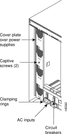
Step 1 Loosen the captive screws and remove the AC power cover plate. See Figure 1-2.

Step 2 Identify the power supply that needs replacement.
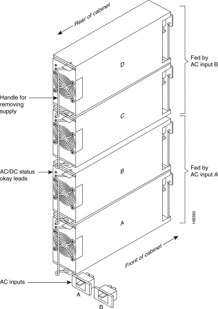
Step 3 Grip the hinged handle on the supply, slightly pull out the supply, then reseat it. This resets the supply's internal power-monitoring circuit. See Figure 1-3 .

Step 4 Check the supply-monitoring circuit on the SCM. First, enter the command resetcd 0 at the control terminal (this resets the power supply monitor on the SCM). After waiting about 10 seconds or more, enter dsppwr and see if the FAIL indicator for the supply turns on. Note which power supply has failed.
Step 5 Pull out the power supply with one hand under the supply.
To install a power supply, perform the following steps:
Step 1 Slide a replacement power supply into the power supply tray and push it to the back. When a supply reaches the end of the slot in the tray, a slight resistance is encountered. Push the power supply slightly farther in to seat the supply correctly.
Step 2 Install the power supply cover plate.
Step 3 Tighten the captive screws on the cover plate until finger-tight.
Step 4 Use the dsppwr command to check the status and output voltage of the replacement power supply. Make sure that the status is OK and the output voltage is 50 V ±2 V.
The cooling unit resides below the card cage. A Fan Assembly has four fans. Individual fans cannot be replaced, so the whole assembly must be replaced when a failure occurs. See Figure 1-4.
Cooling fan trays are hot-swappable. However, the operation must proceed swiftly to keep the system cool enough. Otherwise, the system power must be off. Having the replacement fan tray and tools in the immediate vicinity of the system help ensure that the procedure goes quickly. The required tools are a flat blade screwdriver and a phillips screwdriver.

To replace the cooling unit assembly:
Step 1 Have the replacement fan try and tools ready.
Step 2 Remove the air intake grille at the front of the system by operating the toggle latch at the top-center of the grille with a screwdriver, tilting the grille forward, and lifting it out.
Step 3 Examine the front and back of the fan tray to be familiar with the setup. Note the power connectors attached to the fan tray: the connectors at the fan tray itself are to be disconnected rather than the D-connector at the PE-BC. Also note that the captive screws that hold the fan tray in place are at the front of the fan tray.
Step 4 Loosen the captive screws.
Step 5 At the back of the IGX 8, remove the clamp that secures the power cable for the fans to the chassis.
Step 6 Use a small screw driver or fingertip in this step. For each of the fan power connectors, press in the small plastic latch that locks the connector halves together. With the other hand, grip the part of the connector that is attached to the fan tray and separate the cord from the fan tray. The fan tray now has no power.
Step 7 Push a finger or thumb through the square holes in the chassis to start the fan tray towards the front of the system. Go to the front of the system.
Step 8 Remove the cooling unit and slide in the replacement unit.
Step 9 Plug the power connectors into the fan tray.
Step 10 Make sure all fans are operating.
Step 11 Secure the fan tray assembly by tightening the captive screws.
Step 12 Attach the clamp for the fan power cord to the chassis.
Step 13 After fan tray replacement, install the air intake grille.
Backplane fuses rarely, if ever, need replacement. Backplane fuses are intended to prevent catastrophic damage to the backplane in the event of accidental shorting of -48 VDC on the backplane to chassis ground. This type of event could be caused by bent backplane pins, contact of conductive elements (EMI Cans, EMI Gaskets, etc.) to power pins. These events would most likely happen during a factory build or initial system installation.
Because of design constraints, these fuses need to be in sockets on the backplane and are therefore not readily accessible. A special tool (StrataCom P/N 218090-00) and set of instructions are required for fuse replacement. StrataCom recommends that only factory-trained personnel do the procedure.
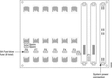
In the IGX 8, backplane fuses exist only on the back of the backplane. Figure 1-5 shows the location of each fuse (F1-F8 and two spare fuses). Note that this figure shows only the upper portion of the backplane.

 | Warning Replacing a fuse should only be done by StrataCom personnel using a special tool with the power off. |
![]()
![]()
![]()
![]()
![]()
![]()
![]()
![]()
Posted: Thu Oct 10 09:05:35 PDT 2002
All contents are Copyright © 1992--2002 Cisco Systems, Inc. All rights reserved.
Important Notices and Privacy Statement.