Table Of Contents
Alarms and Statistics
Automatic Alarm Reporting to Cisco Customer Service
Network Statistics
APS Alarms
What APS Alarms Represent
Trunk Statistics
Trunk Alarms
Physical and Logical Trunk Alarm Summary
Event Logging
Error Messages
BME Alarms
OAM cells
AIS cells
Qbin Statistics
Alarms and Statistics
This chapter describes some of the tools provided for detecting and identifying network and equipment problems that are available to the network operator.
Contents of this chapter include:
• Automatic Alarm Reporting to Cisco Customer Service
• Network Statistics
• APS Alarms
• Trunk Statistics
• Trunk Alarms
• Event Logging
• BME Alarms
Considerably more advanced tools are built into the system software for exclusive use by Cisco Customer Service personnel. These advanced tools require in-depth knowledge of the hardware and software and are used generally to locate the less common types of system problems.
Automatic Alarm Reporting to Cisco Customer Service
Do not perform any disruptive tests or repairs to the network on your own. Before commencing with troubleshooting, contact Cisco Customer Service so that they can provide you with assistance in locating a fault.
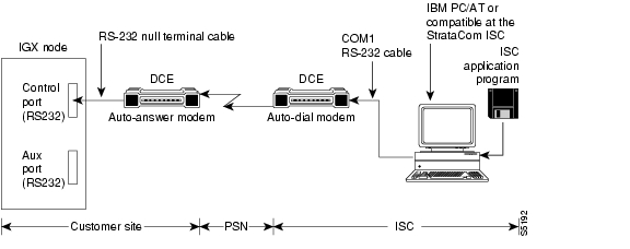
In a network with Cisco BPX 8600 series broadband switches and Cisco IGX 8400 series multiband switches it is recommended that at least one node be configured to transmit alarms automatically to Cisco Customer Service. Figure 27-1 illustrates the hardware configuration required for implementation. This can be a Cisco IGX 8400 series multiband switch.
When an alarm occurs on the network, the autodial modem automatically dials the specified telephone number. An auto-answer modem at Cisco Customer Service answers the call and directs it to a dedicated personal computer. The alarm is logged under the network ID (an ASCII character string) specified by the network administrator and approved by Cisco Customer Service personnel.
If the auto-answer modem at Cisco Customer Service is busy when an alarm arrives, then the autodial modem will keep dialing until the call is completed. A suggested modem is the Codex V.34 RSA 28.8 K modem.
Figure 27-1 Automatic Alarm Reporting
Network Statistics
Cisco WAN Manager collects network statistical data on the operation of the network and stores them in its database. They are available for display on the Cisco WAN Manager console in either tabular form or as bar charts. Statistics can be a useful source of information for troubleshooting problems that do not necessarily cause a major or minor alarm indication or for locating intermittent failures that may occur at random.
The following are the four classes of statistics:
•Trunk statistics
•Line statistics
•Connection statistics
•Frame Relay port statistics
Most statistics are collected on demand and must be enabled by the system operator. The operator can set the collection interval, the sampling times, and the number of collection buckets to tailor the statistics for either long-term network performance evaluation or short term for network troubleshooting.
Table 27-1 lists the statistics categories and the general nature of the statistics collected in each category. Note this is not a complete list of statistics but merely indicates some of the various conditions monitored. For a complete listing, refer to the Cisco WAN Manager User's Guide.
Table 27-1 Typical Statistics Collected
Statistics Category
|
Types of Statistics
|
Trunk statistics
|
Various trunk errors, bipolar violations, frame bit errors, loss of signal, etc.
|
Packet errors and out of frame
|
FastPackets and ATM cells of various types transmitted/dropped
|
Transmitted ATM cell counts
|
Received ATM cell counts
|
Cells with CLP and EFCN set
|
ATM header error counts
|
Trunk statistics (continued)
|
DS3 PLCP error counts
|
Bdata queue dropped cells
|
Line statistics
|
Various circuit line errors, bipolar violations, frame bit errors, loss of signal, and so on
|
Connection statistics
|
Packets transmitted and received
|
Transmitted and received data bytes
|
Frame relay frames transmitted/discarded
|
Frames transmitted with FECN or BECN or DE set
|
Packets with CLP bit set dropped
|
Seconds in service
|
Frame Relay Port
|
Frames transmitted and received
|
Bytes transmitted and received
|
Frames received with CRC or other errors
|
Frames discarded at the connection ingress
|
Frames discarded at the connection egress
|
Frames discarded at the port egress
|
LMI messages sent or dropped for various errors
|
DE frames dropped
|
APS Alarms
The APS alarms are listed in Table 27-2. The list includes the class or state of the alarm: minor, major, information, or clear.
Statistical alarms are not cleared when a Y-red switch occurs. You can clear these statistics as appropriate.
Note On the active line/trunk, alarms (such as LOS and LOF) and statistics (such as error counters) are supported. On the standby line/trunk, alarms are supported but not statistics.
Summary statistics are not supported on a standby line/trunk.
Table 27-2 APS Alarms
Class
|
Name
|
Description
|
Minor
|
APS Standard Mismatch
|
In a two card APS 1+1 configuration, one card is programmed for GR-253 and the other card is programmed for ITUT.
|
Minor
|
APS Card Missing
|
Indicates that either a BXM front card or back card supporting this APS line is detected as missing by a BXM.
|
Clear
|
APS OK
|
APS line is up with no alarms.
|
Clear
|
APS Deactivated
|
APS line is down.
|
Minor
|
APS Lines looped
|
APS line is looped.
|
Minor
|
APS Remote Signal Failure
|
A remote signal failure indicates that there is a problem with the far end signaling information in the K1/K2 bytes.
|
Minor
|
APS Channel Mismatch
|
Can happen in only bidirectional mode and indicates that there is a problem with the underlying APS channel protocol. The receive K2 channel number does not equal the transmit K1 channel number.
|
Minor
|
APS Protection Switch Byte Failure
|
Protection Switch Byte (PSB) failure. In bidirectional mode, indicates that there is an invalid K1 byte. The receive K1 request does not match the reverse request and is less than the transmit K1 request. In all modes, a PSB alarm indicates that K1/K2 protocol is not stable.
|
Minor
|
APS Far-End Protection Failure
|
Far-end protection failure indicates that the far end's protection line is failing. When there is Signal Failure on the protection channel, the remote end sees Far End Protection Fail.
|
Minor
|
APS Architecture Mismatch
|
Architecture mismatch means that the APS configuration on one end of the line does not match the APS configuration at the other side of the line. Specifically GR-253 at one end and ITUT at the other or 1+1 at one end and 1:1 at the other.
|
Info
|
APS Init/Clear/Revert
|
A BXM APS event indicating that the BXM APS has been initialize, or a clear switch or a revert switch has occurred.
|
Info
|
Cannot perform a Clear/Revert switch
|
A BXM APS event indicating that the BXM APS was unable to perform a clear or revertive switch.
|
Info
|
APS Manual switch
|
A BXM APS event indicating that the BXM APS has performed a user-requested manual switch.
|
Info
|
Cannot perform a Manual switch
|
A BXM APS event indicating that the BXM APS was unable to perform a user-requested manual switch.
|
Info
|
APS Signal Degrade LoPri switch
|
A BXM APS event indicating that the BXM APS performed a switch due to a high-priority signal degrade condition. An automatically initiated switch due to a "soft failure" condition resulting from the line BER exceeding a preselected threshold (cnfapsln).
|
Info
|
Cannot perform a Signal Degrade LoPri switch
|
A BXM APS event indicating that the BXM APS was unable to perform a switch due to a low-priority signal degrade condition.
|
Info
|
APS Signal Degrade HiPri switch
|
A BXM APS event indicating that the BXM APS performed a switch due to a high-priority signal degrade condition. An automatically initiated switch due to a "soft failure" condition resulting from the line BER exceeding a preselected threshold (cnfapsln).
|
Info
|
Cannot perform a Signal Degrade HiPri switch
|
A BXM APS event indicating that the BXM APS was unable to perform a switch due to a high-priority signal degrade condition.
|
Info
|
APS Signal Failure LoPri switch
|
A BXM APS event indicating that the BXM APS performed a switch due to a low-priority signal failure condition. An automatically initiated switch due to a signal failure condition on the incoming OC-N line including loss of signal, loss of frame, AIS-L defects, and a line BER exceeding 10-3.
|
Info
|
Cannot perform a Signal Failure LoPri switch
|
A BXM APS event indicating that the BXM APS was unable to perform a switch due to a high-priority signal failure condition.
|
Info
|
APS Signal Failure HiPri switch
|
A BXM APS event indicating that the BXM APS performed a switch due to a high-priority signal failure condition. An automatically initiated switch due to a signal failure condition on the incoming OC-N line including loss of signal, loss of frame, AIS-L defects, and a line BER exceeding 10-3.
|
Info
|
Cannot perform a Signal Failure HiPri switch
|
A BXM APS event indicating that the BXM APS was unable to perform a switch due to a high-priority signal failure condition.
|
Info
|
APS Forced switch
|
A BXM APS event indicating that the BXM APS has performed a user-requested forced switch.
|
Info
|
Cannot perform a Forced switch
|
A BXM APS event indicating that the BXM APS was unable to perform a user-requested forced switch.
|
Info
|
APS Lockout switch
|
A BXM APS event indicating that the BXM APS has performed a user-requested switch, which prevents switching from working line to protection line from taking place.
|
Info
|
Cannot perform a Lockout switch
|
A BXM APS event indicating that the BXM APS was unable to perform a user-requested lockout of protection switch.
|
Info
|
WTR switch
|
A BXM APS event indicating that the BXM APS performed a switch due to a Wait-to-Restore timeout. A state request switch due to a revertive switch back to the working line because the Wait-to-Restore timer has expired.
|
Info
|
Cannot perform a WTR switch
|
A BXM APS event indicating that the BXM APS was unable to perform a switch due to a WTR condition.
|
Info
|
Exercise switch
|
Not supported.
|
Info
|
Cannot perform an Exercise switch
|
Not supported.
|
Info
|
Reverse switch
|
A BXM APS event indicating that the BXM APS performed a switch due to a reverse request. A state request switch due to the other end of an APS bidirectional line performing an APS switch.
|
Info
|
Cannot perform a Reverse switch
|
A BXM APS event indicating that the BXM APS was unable to perform a switch due to a reverse switch request.
|
Info
|
No Revert switch
|
A BXM APS event indicating that the BXM APS performed a switch due to a Do Not Revert. A state request due to the external user request being cleared (such as a forced switch) while using nonrevertive switching.
|
Info
|
Cannot perform a No Revert switch
|
A BXM APS event indicating that the BXM APS was unable to perform a switch due to a Do Not Revert switch request.
|
Minor
|
Standby Line Section Trace
|
APS standby line alarm.
|
Minor
|
Standby Line Path Trace
|
APS standby line alarm.
|
Minor
|
Standby Line path yellow alarm
|
APS standby line alarm.
|
Minor
|
Standby Line path AIS
|
APS standby line alarm.
|
Minor
|
Standby Line loss of pointer
|
APS standby line alarm.
|
Minor
|
Standby Line loss of cell
|
APS standby line alarm.
|
Minor
|
Standby Line plcp yellow alarm
|
APS standby line alarm.
|
Minor
|
Standby Line plcp out of frame alarm
|
APS standby line alarm.
|
Minor
|
Standby Line yellow alarm
|
APS standby line alarm.
|
Minor
|
Standby Line alarm indication signal (AIS)
|
APS standby line alarm.
|
Minor
|
Standby Line out of frame alarm (LOF)
|
APS standby line alarm.
|
Minor
|
Standby Line loss of signal alarm (LOS)
|
APS standby line alarm.
|
Architecture Mismatch means that one side supports 1+1 and other end of the line is configured for 1:1, or the directional or revertive parameter does not match. FW cannot bring the two ends into compliance on the fly; the user must correct the configuration error.
What APS Alarms Represent
The following sections describe the APS alarm types.
Description: An APS alarm occurs in dspalms and dspapsln.
Initial Investigation: APS alarms can be of two types. There are APS-specific alarms and there are line alarms reported by the standby line. The standby line alarm is displayed in the dspapsln screen under "Standby Line Alarm Status". If there are no other APS specific alarms, the standby line alarms will also show under "Current APS Alarm Status". The meaning of the standby line alarms are the same as the meaning of the active line alarms that are reported in the 0x55 Line Alarms command and are discussed in other documentation.
Some of the APS alarms reflect problems with the underlying APS channel protocol, the K1/K2 bytes. The K1 byte carries the request for a switch action on a specific channel to the remote end of the line. The K2 byte indicates the status of the bridge in the APS switch and also carries mode information.
APS alarms representation are described in Table 27-3.
Table 27-3 APS Alarms Representation
Alarm
|
Description
|
Remote Signal FAIL
|
Indicates that there is a problem with the far-end signaling information in the K1/K2 bytes. There is a problem with the protection line's physical layer. One has to disable APS and try to bring up the protection line as a normal line and diagnose the physical layer (by putting in loopback and so on).
|
Channel Mismatch
|
Happens in only bidirectional mode and indicates that there is a problem with the underlying APS channel protocol. The receive K2 channel number does not equal the transmit K1 channel number. There is a problem with the protection line's physical layer. One has to disable APS and try to bring up the protection line as a normal line and diagnose the physical layer (by putting in loopback and so on).
|
Prot Sw Byt FAIL
|
Protection Switch Byte (PSB) failure. In bidirectional mode, indicates that there is an invalid K1 byte. The receive K1 request does not match the reverse request and is less than the transmit K1 request. In all modes, a PSB alarm indicates that K1/K2 protocol is not stable. There is a problem with the protection line's physical layer. One has to disable APS and try to bring up the protection line as a normal line and diagnose the physical layer (by putting in loopback and so on). This alarm is seen if the local end of an APS working line or trunk is connected directly to the remote end's protection line or trunk.
|
APS Card Missing
|
Specifies that this alarm is seen in APS 1+1 configurations when BXM firmware determines that any BXM front or back card is missing. Check dspcds or look in the dsplog to see which card associated with the APS line is missing.
|
FarEnd Prot FAIL
|
Indicates that the far end protection line is failing. When there is Signal Failure on the protection channel, the remote end sees Far End Protection Fail. There is a problem with the protection line's physical layer. One has to disable APS and try to bring up the protection line as a normal line and diagnose the physical layer (by putting in loopback, and so on). If the other end shows the "Architect Mismatch" APS alarm, then the APS standards could be different at each end. To verify, use the cnfcdaps command or cnfapsln command.
|
Architect Mismatch
|
Indicates that one end of the APS line is configured for APS 1+1 and the other end is configured for APS 1:1, which will not work. If the line is configured for GR-253 standard operation an architecture mismatch can also mean that one end is bidirectional and the other end is unidirectional (ITUT will not report this). Verify that the APS architecture is configured the same on either end of the APS lines using the cnfapsln command. This alarm will also be seen if the local end of an APS working line or trunk is connected directly to the remote end's protection line or trunk. In this case, one end of the line usually will have a "Prot Sw Byt FAIL" alarm present. If the other end shows the "FarEnd Prot FAIL" APS alarm then the APS standards could be different at each end. To verify, use the cnfcdaps command or cnfapsln command.
|
Standard Mismatch
|
Indicates that on the local end of an APS 1+1 configuration, one card is running the ITUT standard and the redundant card is running the GR-253 standard. Use the cnfcdaps command to check and change the standard.
|
Usr Line Loop
|
Specifies that the line is looped. Use the dellnlp command to clear the loop. Both working and protection lines are looped when an APS line is looped.
|
APS Standby Line Alarms
|
Specifies that the APS alarms are also shown unless there is a higher priority APS alarm (those above) masking the standby line alarm. The APS standby alarms are the integrated line alarms reported by the standby line in the BXM Line Alarms message (0x55). If one of the alarms are shown, there is a problem with the standby line:
•Rmt Sec Trc Fail
•Rmt Path Trc Fai
•Path Yellow
•Path AIS
•Loss of Pointer
•Loss of Cell
•Remote Framing
•Frame Sync Alarm
•Remote (YEL)
•AIS (BLU)
•Loss of Frm (RED)
•Loss of Sig (RED)
Troubleshoot the line using standard line fault-isolation procedures.
|
Trunk Statistics
The following are the statistics that are collected on trunks at several different levels:
•Physical line statistics apply to each physical port. In the case of IMA trunks, the physical line statistics are tallied separately for each T1 port.
On the both the BPX and the IGX, physical line statistics are displayed on the dspphyslnstats, dspphyslnstathist, and dspphyslnerrs screens. These commands accept only physical line numbers (that is: slot.port).
•Logical trunk statistics refer to counts on trunks that are visible to users as routing entities. This includes physical trunks and virtual trunks.
Logical trunk statistics are displayed on the dsptrkstats, dsptrkstahist, and dsptrkerrs screens. These commands accept only logical trunk numbers and display only logical trunk statistics.
•VI statistics are a subset of the logical trunk statistics.
•Queue statistics are a subset of the logical trunk statistics.
•Channel statistics are not polled by software on trunks. However, they are available if you use the debug command dspchstats.
•Counter statistics use the dspcntrstats command to display in real-time all counter statistics of specified entity.
Table 27-4 is a list of trunk statistics including statistics type, card type, and line type, as applicable.
Table 27-4 Trunk Statistics
Statistic
|
Stat Type
|
Card Type
|
Line Type
|
Total Cells Received
|
Logical
|
UXM/BXM
|
All
|
Total Cells Transmitted
|
Logical
|
UXM/BXM
|
All
|
LOS transitions
|
Physical
|
UXM/BXM
|
All
|
LOF transitions
|
Physical
|
UXM/BXM
|
All
|
Line AIS transitions
|
Physical
|
UXM/BXM
|
T3/E3/SONET
|
Line RDI(Yellow) transitions
|
Physical
|
UXM/BXM
|
T3/E3/SONET
|
Uncorrectable HCS errors
|
Physical
|
UXM
|
T3/E3/SONET
|
Correctable HCS errors
|
Physical
|
UXM
|
T3/E3/SONET
|
HCS errors
|
Physical
|
BXM
|
T3/E3/SONET
|
Line Code Violations, ES, and SES
|
Physical
|
BXM
|
T3/E3
|
Line Parity(P-bit]) errors, ES, and SES
|
Physical
|
BXM
|
T3
|
Path Parity(C-bit) errors, ES, and SES
|
Physical
|
BXM
|
T3
|
Far End Block Errors
|
Physical
|
BXM
|
T3
|
Framing Errors and SES
|
Physical
|
BXM
|
T3/E3
|
Unavailable Seconds
|
Physical
|
BXM
|
T3/E3
|
PLCP LOF and SES
|
Physical
|
BXM
|
T3
|
PLCP YEL
|
Physical
|
BXM
|
T3
|
PLCP BIP-8, ES, SES
|
Physical
|
BXM
|
T3
|
PLCP FEBE, ES, SES
|
Physical
|
BXM
|
T3
|
PLCP FOE, ES, SES
|
Physical
|
BXM
|
T3
|
PLCP UAS
|
Physical
|
BXM
|
T3
|
LOC errors
|
Physical
|
UXM/BXM
|
E3/SONET
|
LOP errors
|
Physical
|
UXM/BXM
|
SONET
|
Path AIS errors
|
Physical
|
UXM/BXM
|
SONET
|
Path RDI errors
|
Physical
|
UXM/BXM
|
SONET
|
Section BIP-8 counts, ES, and SES
|
Physical
|
UXM/BXM
|
SONET
|
Line BIP-24 counts, ES, and SES
|
Physical
|
UXM/BXM
|
SONET
|
Line FEBE counts, ES, and SES
|
Physical
|
UXM/BXM
|
SONET
|
Section SEFS
|
Physical
|
UXM/BXM
|
SONET
|
Line UAS and FarEnd UAS
|
Physical
|
UXM/BXM
|
SONET
|
Clock Loss Transitions
|
Physical
|
UXM
|
T1/E1
|
Frame Loss Transitions
|
Physical
|
UXM
|
T1/E1
|
Multiframe Loss
|
Physical
|
UXM
|
T1/E1
|
CRC errors
|
Physical
|
UXM
|
T1/E1
|
BPV
|
Physical
|
UXM
|
T1
|
Frame bit errors
|
Physical
|
UXM
|
E1
|
Unknown VPI/VCI count
|
Physical
|
UXM/BXM
|
All
|
Errored LPC cell count
|
Physical
|
UXM
|
All
|
Nonzero GFC cell count
|
Physical
|
UXM/BXM
|
All
|
Max Differential Delay
|
Physical
|
UXM
|
T1/E1
|
Uncorrectable HEC errors
|
Physical
|
UXM
|
All
|
Cell Hunt count
|
Physical
|
UXM
|
T1/E1
|
Bandwidth Changed count
|
Physical
|
UXM
|
T1/E1
|
Receive CLP=0 cell count
|
Logical
|
UXM/BXM
|
All
|
Receive CLP=1 cell count
|
Logical
|
UXM/BXM
|
All
|
Receive CLP=0 cell discard
|
Logical
|
UXM/BXM
|
All
|
Receive CLP=1 cell discard
|
Logical
|
UXM/BXM
|
All
|
Transmit CLP=0 cell count
|
Logical
|
UXM/BXM
|
All
|
Transmit CLP=1 cell count
|
Logical
|
UXM/BXM
|
All
|
Receive OAM cell count
|
Logical
|
UXM/BXM
|
All
|
Transmit OAM cell count
|
Logical
|
UXM/BXM
|
All
|
Receive RM cell count
|
Logical
|
UXM/BXM
|
All
|
Transmit RM cell count
|
Logical
|
UXM/BXM
|
All
|
Qbin Statistics to support VSI
For Each Traffic Type:
(V,TS,NTS, ABR, VBR, CBR, BdatB, BdatA,HP)
For UXM trunks:
Qbins 10 through 15
For BXM and UXM line ports:
Qbins 1 through 15
|
|
|
|
Cells served
|
Logical
|
UXM/BXM
|
All
|
Cells received
|
Logical
|
UXM/BXM
|
All
|
Cells discarded count
|
Logical
|
UXM/BXM
|
All
|
Trunk Alarms
The following are the two categories for trunk alarms:
•Logical Trunk Alarms—Provides statistical alarming on cell drops from each of the OptiClass queues. The alarms are maintained separately for virtual trunks on the same port.
•Physical Trunk Alarms—Specifies that a virtual trunk also has trunk port alarms that are shared with all the other virtual trunks on the port. The alarms are cleared and set together for all the virtual trunks sharing the same port.
Physical and Logical Trunk Alarm Summary
Table 27-5 is a list of physical and logical trunk alarms.
Table 27-5 Physical and Logical Trunk Alarms
Alarm Type
|
Physical
|
Logical
|
Statistical
|
Integrated
|
T1
|
E1
|
T3
|
E3
|
SONET
|
LOS
|
X
|
X
|
X
|
X
|
X
|
|
X
|
X
|
OOF
|
X
|
X
|
X
|
X
|
X
|
|
X
|
X
|
AIS
|
X
|
X
|
X
|
X
|
X
|
|
X
|
X
|
YEL
|
X
|
X
|
X
|
X
|
X
|
|
|
X
|
PLCP OOF
|
|
|
X
|
|
|
|
|
X
|
LOC
|
|
|
|
X
|
X
|
|
|
X
|
LOP
|
|
|
|
|
X
|
|
|
X
|
PATH AIS
|
|
|
|
|
X
|
|
|
X
|
PATH YEL
|
|
|
|
|
X
|
|
|
X
|
PATH TRC
|
|
|
|
|
X
|
|
|
X
|
SEC TRC
|
|
|
|
|
X
|
|
|
X
|
ROOF
|
X
|
X
|
|
|
|
|
|
X
|
FER
|
X
|
X
|
|
|
|
|
|
X
|
AIS16
|
X
|
X
|
|
|
|
|
X
|
X
|
IMA
|
X
|
X
|
|
|
|
|
|
X
|
NTS Cells Dropped
|
|
|
|
|
|
X
|
X
|
|
TS Cells Dropped
|
|
|
|
|
|
X
|
X
|
|
Voice Cells Dropped
|
|
|
|
|
|
X
|
X
|
|
Bdata Cells Dropped
|
|
|
|
|
|
X
|
X
|
|
BdatB Cells Dropped
|
|
|
|
|
|
X
|
X
|
|
HP Cells Dropped
|
|
|
|
|
|
X
|
X
|
|
CBR Cells Dropped
|
|
|
|
|
|
X
|
X
|
|
VBR Cells Dropped
|
|
|
|
|
|
X
|
X
|
|
ABR Cells Dropped
|
|
|
|
|
|
X
|
X
|
|
Event Logging
All trunk log events are modified to display the virtual trunk number. The examples in Table 27-6 and Table 27-7 show the log messaging for activating and adding a virtual trunk 1.2.1.
Table 27-6 IGX Log Messaging for Activating and Adding a VT
Class
|
Description
|
Info
|
NodeB at other end of TRK 1.2.1
|
Clear
|
TRK 1.2 OK
|
Major
|
TRK 1.2 Loss of Sig (RED)
|
Clear
|
TRK 1.2.1 Activated
|
Table 27-7 BPX Log Messaging for Activating and Adding a VT
Class
|
Description
|
Info
|
NodeB at other end of TRK 1.2.1
|
Clear
|
TRK 1.2.1 OK
|
Major
|
TRK 1.2.1 Loss of Sig (RED)
|
Clear
|
TRK 1.2.1 Activated
|
Error Messages
The following are the added error messages for virtual trunks:
Message
|
Description
|
"Port does not support virtual trunking"
|
Port is not configured for virtual trunks
|
"Port configured for virtual trunking"
|
Port is not configured for a physical trunk
|
"Invalid virtual trunk number"
|
Virtual trunk number is invalid
|
"Maximum trunks per node has been reached"
|
Trunk limit per node has been reached
|
"Invalid virtual trunk VPI"
|
Virtual trunk VPI is invalid
|
"Invalid virtual trunk traffic class"
|
Virtual trunk traffic class is invalid
|
"Invalid virtual trunk VPC type"
|
Virtual trunk VPC type is invalid
|
"Invalid virtual trunk conid capacity"
|
Virtual trunk conid capacity is invalid
|
"Mismatched virtual trunk configuration"
|
Ends of virtual trunk have different configuration
|
"Maximum trunks for card has been reached"
|
The trunk card is out of VIs
|
BME Alarms
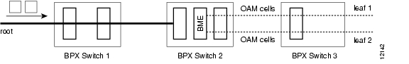
OAM cells
OAM cells coming into the root are multicast into the leaves along with data as shown in Figure 27-2.
Figure 27-2 OAM Cells
AIS cells
AIS cells are automatically generated on the leaves, as shown in Figure 27-3, when:
•There is a loss of signal (LOS) on the far end of the root
•There is a trunk failure
•When the root connection is downed using the dncon command
Figure 27-3 Alarms
Qbin Statistics
Qbin statistics allow network engineers to properly engineer and overbook the network on a per Class-of-Service (or per Qbin) basis.
Switch software collects statistics for the following:
•BXM Automatic Routing Management Qbin (Qbin numbers 1 to 9) on Automatic Routing Management trunks.
•Qbin numbers 10 to 15 assigned for use by VSI traffic. These statistics are helpful for configuring MPLS or PNNI controllers.
The resulting statistics are displayed in Cisco WAN Manager and may also be viewed by using the command line interface (CLI).
The following are the Qbin statistics:
•cells served
•cells received
•cells discarded
Because all Qbins provide the same statistical data, the Qbin number together with its statistic forms a unique statistic type. One unique statistic type is "Cells served out of Qbin-10." Another unique statistic type is "Cells discarded by Qbin-11," and so on.
Trunk and port counter statistics for Qbins 1 to 15 can be collected by SNMP.
Qbin summary and counter statistics can be enabled as TFTP or USER (not AUTO) interval statistics. Unlike the cell discard statistics on BXM trunk Qbins 1 to 9, all cell-discard statistics on Qbins 10 to 15 are not AUTO statistics.
The next two sections are a brief introduction the commands described in the Cisco WAN Switching Command Reference. For detailed explanations and tables of Qbin statistics, see the Qbin commands in the Cisco WAN Switching Command Reference and the Cisco WAN Manager User's Guide.
Interval Statistics
The following are the two ways you can collect interval traffic statistics (per Qbin) on the switch:
•Cisco WAN Manager's SCM collects and views statistics on all BXM trunks on a BPX (TFTP statistics). See the Cisco WAN Manager documentation.
•The command line interface (CLI).
Table 27-8 lists the commands that are used to collect interval statistics.
Table 27-8 Interval Statistics Commands
Name
|
Description
|
cnftrkstats
|
Collects the USER statistics of one statistic type on a specific specified trunk.
|
dsptrkstathist
|
Views the interval statistics of one statistic type on a specific specified trunk.
|
cnfportstats
|
Collects the USER statistics of one statistics type on a specified port.
|
dspportstathist
|
Views the statistics of one statistics type on a specified port.
|
Summary and Counter Statistics
Table 27-9 lists the commands that are used to collect summary and counter statistics.
Table 27-9 Summary and Counter Statistics Commands
Name
|
Description
|
dspcntrstats
|
Views, in real-time, all counter statistics of a specified entity.
|
dspqbinstats
|
Views all the Qbin summary statistics on a specified trunk or port.
|
clrtrkerrs
|
Resets or clears the summary statistics of all statistic types on a specified trunk.
|
clrportstats
|
Resets or clears the summary statistics of all statistics types on a specified link.
|