cc/td/doc/product/wanbu/bpx8600/9_3_3
hometocprevnextglossaryfeedbacksearchhelp
PDF

Table Of Contents

Initial BPX 8600 Node Configuration

Summary of Configuration Procedures

Initial Node Configuration Summary

Command Sequences for Setting Up Nodes

Summary of Commands


Initial BPX 8600 Node Configuration


This chapter guides you through the initial node configuration that must be done before you can set up network management, which will enable you to use Cisco WAN Manager workstation to configure network connections.

Contents of this chapter include:

Summary of Configuration Procedures

Initial Node Configuration Summary

Command Sequences for Setting Up Nodes

Summary of Commands

Before proceeding with this chapter, make sure you have completed all procedures in Part Two, Installation. It is assumed that the BPX chassis is mounted, BPX cards are installed, cables connected, temporary terminal or network management station is connected, peripherals connected, and the BPX node is powered up.

You are now ready to do the following:

Initially configure the node

Configure node name

Configure node number

Configure LAN IP address and subnet mask

Configure time zone

Configure network IP relay addresses

Configure trunks (adding the new node to the network)

Configure lines and ports (enabling and configuring user ports)

Add and Configure Connections

Summary of Configuration Procedures

This section summarizes the configuration steps as an overview to the procedures in the following chapters.

For a description of the commands used to operate a BPX switch, refer to the Cisco WAN Switching Command Reference.

For node installation and operation, refer to the applicable reference publications: Cisco IGX 8400 Series Reference and Cisco MGX 8220 Reference.

Initial Node Configuration Summary

This section is an overview of adding nodes and trunks by using the command line interface.

As a minimum, you should configure the nodes, as applicable, by using:

name (cnfname)

date (cnfdate)

time (cnftime)

timezone (cnftmzn)

trunks upped (uptrk)

trunks added (addtrk or addshelf)

You may add connections now or later, after configuring the nodes for operation with the Cisco WAN Manager NMS manager.

If you are naming the node after a city or place that contains more than eight characters, you will have to abbreviate the name to create a valid network node name. The name must be unique across the network.

The following are the basic tasks to configure a BPX switch:

1. Set up the node.

a. Configure the node name (cnfname)
Before you can add a node to the network, you must assign it a unique node name.
All nodes initially have the default name NODENAME. The node name consists of one to eight printable characters (beginning with a letter), and cannot contain spaces. This new name is distributed automatically to other nodes in the network. For example, to assign the node the name of alpha, enter:

cnfname alpha

b. Configure the time zone (cnftmzn)
Each node must have a time zone. To set the time zone for the node to Greenwich Mean Time, for example, enter:

cnftmzn GMT

c. Configure date (cnfdate)

d. Configure time (cnftime)

e. Configure the LAN interface (cnflan)

f. Configure the auxiliary or terminal ports to support any necessary external devices such as a local printer, an autodial modem, or an external multiplexer attached to the unit (cnfprt, cnfterm, cnftermfunc)

2. Set up the trunks to other routing nodes.
Verify that the correct cards are in both the local and remote nodes (dspcds).

a. Up the trunks at each node (uptrk).

b. Configure any parameters required for the trunk at each node (cnftrk).

c. Add the trunks at each node (addtrk).

d. Set up Y redundancy if desired (addyred).

3. If you are using an IGX Interface Shelf, configure it as a shelf.

a. Up the trunk from the UXM to the BPX switch by using (uptrk). Shelf trunks for the IGX must be upped on both the BPX routing switch and the shelf before the shelf can be joined to the Routing Network.

b. Contact Cisco Customer Service to configure the IGX shelf option.

c. At the BPX switch, add the IGX switch as a shelf to the BPX (addshelf).

4. Adding the MGX 8220 or MGX 8800 Shelf.

a. At the BPX switch, add the MGX as a shelf to the BPX switch (addshelf).

5. Set up ATM service lines and ports.

a. Activate the line (upln).

b. Configure the line (cnfln).

c. Activate the ports (upport).

d. Configure the ports (cnfport).

6. Set up ATM connections.

a. Add connections (addcon).

b. Configure a connection type (cnfcont).

7. Set up ATM to Frame Relay (ATF) connections.

a. Add the connections (addcon).

b. Configure connection classes (cnfcls).

c. Configure connection groups (addcongrp).

8. Set up Interface Shelf Frame Relay Connections in Tiered Networks.

a. Refer to the Cisco WAN Manager User's Guide.

b. Frame Relay connections terminated at an MGX 8220 or MGX 8800 Shelf. You add and manage these by using the Cisco WAN Manager Connection Manager through SNMP. All connections are treated as end-to-end.

c. ATM connections terminated at an MGX 8220 or MGX 8800 Shelf. You add and manage these by using the Cisco WAN Manager Connection Manager through the SNMP protocol. All connections are treated as end-to-end.

The following is the dspnodescreen, which is displayed at the shlf3igx node, shows that it is connected to the BPX switch through UXM trunk 8.1:


shlf3IGX TN edgar IGX 8 9.3 June 20 2000 09:24 PDT

BPX Switching Shelf Information

Trunk Name Type Alarm
8.1   hubone BPX MAJ


Last Command: dspnode


Next Command:

Command Sequences for Setting Up Nodes

Follow the illustrated command sequences to perform these node-related tasks:

Set up a node (see Figure 17-1).

View information about the presence of the cards and system power (see Figure 17-2).

Configure an interface for a control terminal that is connected to the node (see Figure 17-3).

Remove a node from a network (see Figure 17-4).

Add an interface shelf (see Figure 17-5).

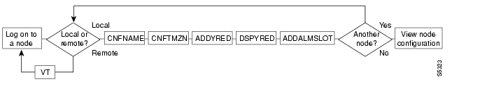
Figure 17-1 Setting Up Nodes

Figure 17-2 Viewing the Node Configuration

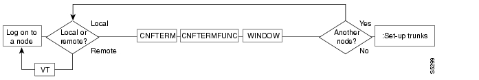
Figure 17-3 Configuring the Node Interface for a Local Control Terminal

Figure 17-4 Removing a Node From the Network

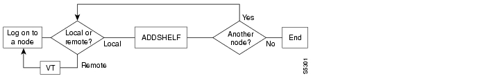
Figure 17-5 Add an Interface Shelf to the Network

Summary of Commands

A description of each node command is described in Table 17-1.

Table 17-1 Commands for Setting Up a Node 

Name
Description

addalmslot

Adds an alarm slot.

addcdred

Adds card redundancy for SONET APS 1+1 across two BXM cards.

addctrlr

Adds a PNNI VSI controller to a BPX node through an AAL5 interface shelf.

addshelf

Adds a trunk between an IGX or BPX core switch shelf and an interface shelf.

addyred

Adds Y-cable redundancy.

cnfasm

Configures an ASM card.

cnfdate

Configures the date.

cnffunc

Configures the system function.

cnfname

Configures the node name.

cnfprt

Configures the printing functions.

cnfterm

Configures the terminal port.

cnftime

Configures the time.

cnftmzn

Configures the time zone.

delalmslot

Deletes the alarm slot.

delshelf

Deletes a trunk between a IGX/BPX core switch shelf and interface shelf.

delcdred

Deletes Y-cable redundancy (disables card redundancy (for SONET Automatic Protection Switching feature).

delyred

Deletes Y-cable redundancy.

dspasm

Displays the ASM card configuration.

dspcd

Displays the card.

dspcds

Displays the cards.

dsplancnf

Displays the LAN configuration.

dspctrlrs

Displays all PNNI VSI controllers on a BPX node.

dsplmistats

Displays the LMI statistics.

dspnds

Displays the nodes.

dspnode

Displays the summary information about interface shelves.

dsptermcnf

Displays the terminal configuration.

dsptermfunc

Displays the terminal port configuration.

dspprtcnf

Displays the print configuration.

dsppwr

Displays the power.

dspyred

Displays Y-cable redundancy.

prtyred

Prints Y-cable redundancy.

upcd

Ups the card.

window

Provides the window to an external device.


hometocprevnextglossaryfeedbacksearchhelp

Posted: Tue May 10 21:08:39 PDT 2005
All contents are Copyright © 1992--2005 Cisco Systems, Inc. All rights reserved.
Important Notices and Privacy Statement.