|
|

This chapter describes the BPX Switch's common core hardware components:
The BPX switch Common Core group includes the components shown in Figure 3-1:
The BCC-4V provides a 16 x 32 crosspoint switch architecture to extend the BPX peak switching capability from 9.6 up to 19.2 Gbps peak. The BCC-4V also provides 4 MBytes of BRAM and 128 MBytes of DRAM.
The functions of the common core components include:
 |
Note The three types of BCCs with their proper backcards may be operated together temporarily for maintenance purposes, for example, replacing a failed controller card. Throughout a network, individual BPX switches may have either a single BCC-4V controller card or a pair of the identical type of BCC. |

The term BCC is used in this manual to refer to the functional operation of the Broadband Controller Card. When a difference in operation does occur, the specific type of BCC is specified.
The BCC-4V provides a 16 x 32 cross-point architecture that increases the peak switching capacity of the BPX switch to 19.2 Gbps, with a sustained non-blocking throughput of 9.6 Gbps.
The Broadband Controller Card performs these major system functions:
Each Broadband Controller Card includes the following:
The BPX switch is a space switch. It employs a crosspoint switch for individual data lines to and from each port. The switching fabric in each BPX switch consists of three elements for the BCCs (see Figure 3-2):
Only one connection at a time is allowed to an individual card.
With the BPX switch equipped with two BCCs, the cell switching is completely redundant in that there are always two arbiters, two crosspoint switches, two completely independent data buses, and two independent polling buses.
The BCC incorporates non-volatile flash EEPROM which permits new software releases to be downloaded over the network and battery-backup RAM (BRAM) for storing user system configuration data. These memory features maintain system software and configuration data even during power failures, eliminating the need to download software or reconfigure after the power returns.
The BPX switch cell switching is not synchronized to any external clocks; it runs at its own rate. No switch fabric clocks are used to derive synchronization nor are these signals synchronized to any external sources.
Node clocking is generated by the BCC. Because the BPX switch resides as an element in a telecommunications network, it is capable of synchronizing to higher-stratum clocking devices in the network and providing synchronization to lower stratum devices. The BCC can be synchronized to any one of three different sources under software control:
The BCC clock circuits provide clocking signals to every other card slot. If a function card needs to synchronize its physical interface to the BPX switch clock, it can use this timing signal to derive the proper reference frequency. These reference frequencies include DS1, E1, DS3, and E3.

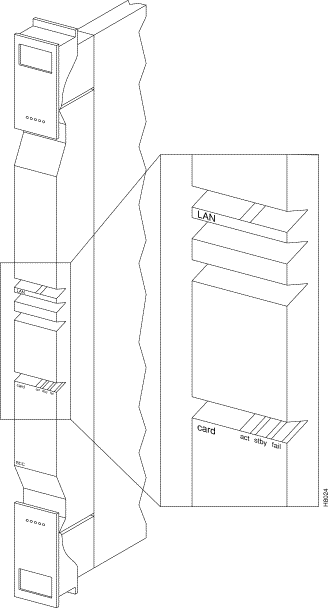
The BCC front panel has four Led, three card status LEDs, and a LAN LED. (See Figure 3-3 and Table 3-1.)
| Number | Indicator | Function |
|---|---|---|
1 | LAN | Indicates there is data activity over the Ethernet LAN port. |
2 | card - act | Card active LED indicates this BCC is online and actively controlling the node. |
3 | card - stby | Card standby LED indicates this BCC is offline but is ready to take over control of the node at a moments notice. |
4 | card - fail | Card fail LED indicates this BCC has failed the internal self-test routine and needs to be reset or replaced. |

The BCC runs self-tests continuously on internal functions in the background and if a failure is detected, the fail LED is lighted. If the BCC is configured as a redundant pair, the off-line BCC is indicated by the lighted stby LED. The stby LED also flashes when a software download or standby update is in progress. The LAN LED indicates activity on the Ethernet port.
To operate the BPX switch at up to a 19.2 Gbps peak throughput, these components are required:
Switch software does not allow node operation at 19.2 Gpbs unless it can read the backplane NOVRAM to verify that the backplane is a 19.2 Gbps backplane.
The 19.2 backplane can be visually identified by the small white card slot fan fuses at the bottom rear of the backplane. These fan fuses are approximately 1/4 inch high and 1/8 inch wide. The 9.6 Gbps backplane does not have these fuses.
If the BPX switch is a late model, then a 19.2 Gbps backplane is installed. You can be verify this by running the despond command which will display "Word #2 =0001" if the backplane NOVRAM has been programmed. If anything else is displayed, visually check the backplane for the fuses.
If the backplane is a 19.2 Gbps backplane, but the backplane NOVRAM has not been set to display Word #2 =0001, then you may use the cnfbpnv command to program the NOVRAM:
Are you sure this is a new backplane (y/n).
Step 2 Enter y
Step 3 Confirm that the change has been made by entering dspbpnv to confirm the response:
Word #2 =0001
 |
Note If the change does not take place, it will be necessary to change the backplane NOVRAM. Contact Cisco Customer Service. |
Step 4 Enter switchcc to make switch software recognize the change.
If the backplane is not a 19.2 Gbps backplane, contact Customer Customer Service.
The backcards for the Broadband Controller Card serve as an interface between the BPX switch and the BPX switch network management system.
For the BCC-4V, the backcard is the BCC-3-BC. (These backcards are also known as the BCC backcards).
The BCC-4V provides important features such as support for up to 19.2 Mbps peak operation with BXM cards. Both BCCs in a node should be of the same type.
The backcard provides these interfaces:
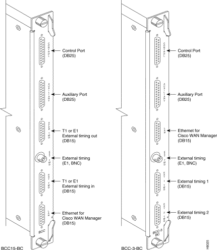
The face plate connectors are described in Table 3-2 and Table 3-3 and shown in Figure 3-4. The BCC15-BC is shown on the left and the BCC-3-BCC is shown on the right.
For specifications on cabling, refer to Chapter 31, BPX Switch Cabling Summary.
| Connector | Function |
|---|---|
CONTROL | A DB25 connector for a VT100 or equivalent terminal for a basic terminal connection enabling you to use the command line interface commands. You can also connect to a dial-in modem for remote service support or other network management dial-up access. This is a bidirectional RS232 communications port. It is not used for CWM Network Management; the LAN connector is used for CWM Network Management. |
AUXILIARY | A DB25 connector for a system printer. This is a one-way, RS232 outgoing port. |
XFER TMG | DB15 connector that supplies an 8-kHz timing signal (RS422 type output that is synchronized to the BPX switch system clock.) |
EXT TMG | A 75-ohm BNC connection for clock input. An E1 source with 75 ohm impedance typically uses this connector. If the shield on the cable needs grounding, slide the BCC back card out and jumped connector JP1 across its two pins. |
EXT TMG | DB15 connector for a primary and optional redundant external source of system clock. A T1 source with 100 ohm impedance or an E1 source with 100/120 ohm impedance typically use this connector. |
LAN | A DB15 Ethernet LAN connection for connecting to a CWM NMS. You can also connect a terminal (or NMS other than CWM) to the BPX switch LAN port via Ethernet. However, only the CWM NMS provides full management configuration and statistics capabilities via SNMP and TFTP. |
| Connector | Function |
|---|---|
CONTROL | A DB25 connector for a VT100 or equivalent terminal for a basic terminal connection using command line interface commands. You can also connect to a dial-in modem for remote service support or other network management dial-up access. This is a bidirectional RS232 communications port. This is not used for CWM Network Management; the LAN connector is used for CWM Network Management. |
AUXILIARY | A DB25 connector for a system printer. This is a one-way, RS232 outgoing port. |
LAN | A DB15 Ethernet LAN connection for connecting to a CWM NMS. A terminal or NMS other than CWM can also be connected to the BPX switch LAN port via Ethernet. However, only the CWM NMS provides full management configuration and statistics capabilities via SNMP and TFTP. |
EXT TMG | A 75-ohm BNC connection for clock input. An E1 source with 75 ohm impedance typically uses this connector. If the shield on the cable needs grounding, slide the BCC back card out and jumper connector JP1 across its two pins. |
EXT 1 TMG | DB15 connector for a primary and optional redundant external source of system clock. A T1 source with 100 ohm impedance or an E1 source with 100/120 ohm impedance typically use this connector. |
EXT 2 TMG | Provides for an external clock source redundant to the EXT 1 TMG source. |

Another function of the line module back card is to provide two low-speed, serial communications ports, as described in Table 3-3:
CONTROL port
A bidirectional port for connecting the BPX switch to a local terminal or to a modem for a remote terminal dial-in connection.
AUXILIARY port
An output only port, typically used to connect to a printer dedicated to printing logs.
The Cisco WAN Manager NMS is connected to the LAN port on the BCC backcards. When control is provided via an Ethernet interface, you configure the node IP address by using the cnflan command for the BPX switch. For redundancy, also configure the LAN ports on both BCC back cards, each connected to an AUI adapter.
The LAN port of the primary Broadband Control Card is active. If the secondary Broadband Control Card becomes primary (active), then its LAN port becomes active. The Cisco WAN Manager workstation will automatically try to restore communications over the LAN and will interface with the newly active Broadband Controller Card.
For small networks, one Cisco WAN Manager workstation is adequate to collect statistics and provide network management. For larger networks additional Cisco WAN Manager workstations may be required. Refer to the Cisco WAN Manager Operations Guide.
The ASM and LM-ASM cards are non-critical cards used for monitoring the operation of the node and not directly involved in system operation. Therefore, there is no provision or requirement for card redundancy.
The ASM card provides a number of support functions for the BPX switch:
BPX switch system software commands the ASM card to activate the major and minor alarm indicators and relays.
There are four significant circuits controlled by the ASM processor:
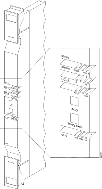
The front panel displays the status of the node and any major or minor alarms that might be present. Figure 3-5 illustrates the front panel of the ASM card. Each front panel feature is described in
Table 3-4.
| Number | Controls/Indicator | Function |
|---|---|---|
1 | alarms LEDs | A red major alarm and a yellow minor alarm indicator to display the status of the local node. In general, a major alarm is affects service whereas a minor alarm is a failure that does not affect service. |
2 | dc LEDs | Two green LEDs display the status of the two DC power busses on the Stratabus backplane. ON indicates voltage within tolerance. OFF indicates an out-of-tolerance voltage. |
3 | ACO/hist LEDs | ACO LED (yellow) lights when you press the front panel ACO pushbutton. History LED (green) indicates an alarm has been detected by the ASM at some time in the past but might not be clear at present time. |
4 | ACO switch | When operated, releases the audible alarm relay. |
5 | history clear switch | Extinguishes the history LED if the alarm condition has cleared. If the alarm is still present when the history clear switch is thrown, the history LED will stay lit. |
6 | card status LEDs | Active (green) indicates the card is online and clear of alarms. Standby (yellow) indicates the card is offline. Fault (red) indicates a card failure is detected by the card self-test diagnostics. |

The LM-ASM backcard must be installed in back slot number 15.
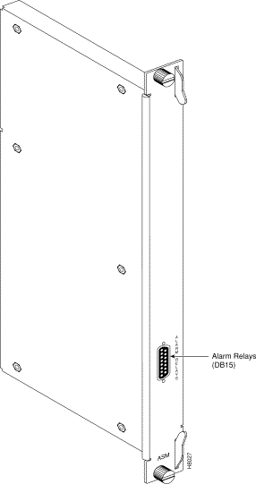
Figure 3-6 illustrates the face plate of the LM-ASM which contains a single subminiature connector (see Table 3-5). The Alarm Relay connector provides dry-closure (no voltage) relay contact outputs.
| Number | Connector/Indicator | Function |
|---|---|---|
1 | ALARM RELAYS | A DB15 connector for alarm relay outputs. Refer to Chapter 3 or Appendix C for pinouts. |

The BPX switch may be equipped with a backplane that supports either a 9.6 or up to 19.2 Gbps operation. The 19.2 Gbps backplane can physically be identified by the card slot fuses on the bottom rear of the backplane. All BPX switch modules are interconnected by the BPX switch StrataBus backplane physically located between the front card slots and the back card slots.
Although the ATM data paths between the switching fabric and the interface modules are individual data connections, there are also a number of system bus paths for controlling the operation of the BPX switch. The StrataBus backplane, in addition to the 15 card connectors, contains these signal paths:
All StrataBus wiring is completely duplicated and the two sets of bus wiring operate independently to provide complete redundancy. Either the A-side wiring or B-side wiring is enabled at any particular time by signals on the Control bus.
![]()
![]()
![]()
![]()
![]()
![]()
![]()
![]()
Posted: Fri Jul 27 17:13:46 PDT 2001
All contents are Copyright © 1992--2001 Cisco Systems, Inc. All rights reserved.
Important Notices and Privacy Statement.