|
|

Table Of Contents
Descriptions for Statistics CLI Commands
burnfwrev (Burn Firmware Image into Card(s)
clrcderrs (Clear Detailed Card Errors)
clrcnf (Clear Configuration Memory)
cnfabrparm (Configure Assigned Bit Rate Queue Parameters)
cnfbusbw (Configure UXM Card Bus Bandwidth)
Descriptions for Statistics Fields on cnfcdparm Screen
cnfcdpparm (Configure CVM Card Parameters)
cnfcftst (Configure Communication Fail Test Pattern)
cnfchstats (Configure Channel Statistics Collection)
cnfchts (Configure Channel Timestamp)
cnfclnparm (Configure Circuit Line Parameter)
cnfclnsigparm (Configure Circuit Line Signalling Parameters)
cnfcmparm (Configure Connection Management Parameters)
cnfdiagparm (Configure Diagnostic Test Parameters)
cnfdlparm (Configure Download Parameters)
cnfecparm (Configure Echo Canceller Parameters)
cnffstparm (Configure ForeSight Node Parameters)
cnflnparm (Configure ATM Line Card Parameters)
cnflnsigparm (Configure Line Signalling Parameters)
cnflnstats (Configure Line Statistics Collection)
cnfclnstats (Configure Circuit Line Statistics)
cnfmxbutil (Configure Muxbus Utilization)
cnfnodeparm (Configure Node Parameter)
cnfnwip (Configure Network IP Address)
cnfphyslnstats (Configure Physical Line Statistics)
cnfportstats (Configure Port Statistics Collection)
cnfrobparm (Configure Robust Alarms Parameters)
cnfslotstats (Configure Slot Statistics Collection)
cnftcpparm (Configure TCP Parameters)
cnftermfunc (Configure Terminal Port Functions)
cnftlparm (Configure Trunk-Based Loading Parameters)
cnftrkparm (Configure Trunk Card Parameters)
Physical and Virtual Parameters You Can Configure Using cnftrkparm
cnftrkstats (Configure Trunk Statistics Collection)
cnftstparm (Configure Card Test Parameters)
cnfuiparm (Configure User Interface Parameters)
cnfuvmchparm (Configure Channel Parameters on a UVM)
cnfvchparm (Configure Voice Channel Parameter)
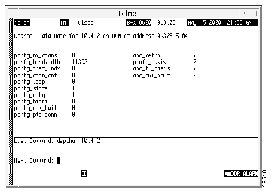
dchst (Display Channel Status)
drtop (Display Route Op Table)
dspabortlog (display abort log)
dspasich (Display ASI Channel Routing Entry)
dspcardstats (Display BXM Card Statistics)
BXM Card Statistics Descriptions for dspcardstats Command
dspcderrs (Display Card Errors)
dspcftst (Display Communication Fail Test Pattern)
dspchan (Display Channel Configuration)
dspchstatcnf (Display Statistics Enabled for a Channel)
dspchstathist (Display Statistics History for a Channel)
dspchstats (Display All Enabled Statistics for a Channel)
Descriptions for Statistics Fields on dspchstats
dspclnstatcnf (Display Circuit Line Statistics Configuration)
dspclnstathist (Display Statistics History for a Circuit Line)
dspcnf (Display Configuration Save/Restore Status)
dspdutl (Display Data Channel Utilization)
dspecparm (Display Echo Canceller Parameters)
dspfwrev (Display Firmware Revision)
dsphitless (Display Statistical History of Hitless Rebuilds)
dsplnstatcnf (Display Statistics Enabled for a Line)
dsplnstathist (Display Statistics Data for a Line)
dspphyslnstatcnf (Display Statistics Enabled for a Physical Line)
dspphyslnstathist (Display Statistics Data for a Physical Line)
dspportstatcnf (Display Statistics Enabled for a FR Port)
dspportstathist (Display Statistics History for An FR Port)
dsprobst (Display Robust Statistics)
dsprrst (Display Reroute Statistics)
dspslotstatcnf (Display Statistics Enabled for a BXM Card Slot)
dspslotstathist (Display Statistics History for a BXM Card)
dspstatmem (Display Statistics Memory Use)
dspswlog (display software error log)
dsptcpparm (Display TCP Parameters)
dsptrkcons (Display Trunk Connection Counts)
dsptrkmcons (Display Trunk Connection Counts by Master Node)
dsptrkstatcnf (Display Statistics Enabled for a Trunk)
dsptrkstathist (Display Statistics History for a Trunk)
getfwrev (Get Firmware Revision)
rststats (Reset Statistics Collection Time)
tstbadubus (test NTM corruption problem)
upgdlogcd (upgrade logical card database)
SuperUser Commands
Introduction
This chapter contains detailed descriptions of the Cisco WAN switching software SuperUser commands for Release 9.3.0. The Cisco WAN switching software SuperUser command descriptions appear in alphabetical order. You need user privilege level 0 (zero) to use these commands.
CautionThese commands are intended to be restricted to Cisco personnel and other qualified users, such as system administrators. Do not distribute this information to casual users because using some SuperUser commands improperly could lead to system malfunction or complete failure.
Also note that once you log into a node as SuperUser (user privilege level 0), you will have access to all the SuperUser commands in this guide throughout the entire session until you log off that node.
General Information
Note
Because the privilege level for all SuperUser commands is 0, the privilege level does not appear in the command definition.Table 1-2 lists the Cisco WAN switch software level 0 (SuperUser) commands in alphabetical order. The table also lists the nodes on which each command is available and whether you can include the command in a job. To access these commands, type in SuperUser at the login prompt. Enter the SuperUser password and the password prompt. To exit a command at any point, press the Delete key.
The screen examples in this chapter are based on a network containing an IGX or BPX or any combination of these nodes. For detailed descriptions of commands requiring user-privilege levels 1-6, refer to the Cisco WAN Switching Command Reference.
Note
Descriptions for Statistics CLI Commands
This section briefly describes the statistics command line interface (CLI) descriptions that are provided for various statistics commands (for example, cnfchstats, cnflnstats, cnfportstats, and so on.) Each statistics command displays various field names on the CLI. Note that the descriptions provided in the various statistics description tables may vary from the actual description of the field name as it appears on the switch software command line interface statistics screens.
Only BXM card statistics descriptions are provided; however, note that many of the UXM card statistics are similar or identical to those used for the BXM card. This means that in many cases, the description may also apply to the UXM card. Note also that the statistics descriptions provided in the various tables may not always map directly to the CLI field names, but in many cases, they provide a description of the statistic that is sent from the card firmware to the switch software CLI (through ComBus messages from the firmware to switch software).
Note
Statistics Command Descriptions
There are several tables provided, which contain ComBus messages, along with descriptions of how each message is used by the switch software. Note that in many cases, the ComBus message description provides a description of the statistics field name on the CLI screen display, on dspchstats, dspchstathist, and so on.
The tables have the following columns:
•
•
•
•
–
–
–
–
–
•
Functional Description of Channel Statistics
This operation provides a way for the software to collect channel statistics. The number of channel statistics that can be collected is limited and configurable by software. Note that all of these stats are not available on the Monarch firmware at one time. For the stats that are not configured, a value of zero will be returned during the "get" operation.
In the description column of the screen display, the numbers in brackets indicate how many stats-per-connection need to be configured on the card for the specific statistic to be available over the ComBus interface. [ALL] indicates the statistic is available regardless of the number of configured stats-per-connection. If the number inside the [ ]s is preceded by "A:", that means that the statistic is available when primary statistics are requested for the connection. If the number inside the [ ]s is preceded by "B:", that means the statistic is available when secondary statistics are requested for the connection.
Summary of Commands
Table 1-1 contains a list of SuperUser commands.
burnfwrev (Burn Firmware Image into Card(s)
The burnfwrev command burns a new firmware image into a specific card.
Attributes
Associated Commands
dspfwrev, getfwrev
Syntax
burnfwrev <image name> <slot number>
Function
This command is used to burn a firmware image into the memory of a specific card. Before you use burnfwrev, the firmware image must already reside in the controller card's memory. (Use getfwrev to load the image to the controller.)
A few seconds after you enter burnfwrev, the system displays a screen similar to the one in Figure 1-1, then the Burn Address column starts to indicate the addresses that are being "burned." When burnfwrev finishes, the status changes to "Complete."
After all cards at a node have been updated with burnfwrev, enter the following to clear the firmware image from the controller card's buffer area:
getfwrev 0.0 node_name
Use the dspfwrev command to display the firmware image status on the controller card at any time after burnfwrev has finished.
At the SuperUser level (0), you can use burnfwrev only to change the revision level of a card's firmware. If the firmware revision would result in a new model number for the card, only a user with a higher privilege level can burn the firmware image. In this case, you would have to call the TAC to execute the command.
Figure 1-1 burnfwrev—Burn Firmware Revision into Card
gamma TRM SuperUser Rev: 9.2 Aug. 17 1998 14:28 PDTFirmware Size StatusF.D.A 256 K Burning into slot 19 (6 lives)File Address Length CRC Burn Address0 800000 10 E986E9391 800800 410 22996DDA2 801000 2D40 B212147F3 805E60 480 85CB29EA4 80A630 70 57A938AE5 80A6B0 20 4B9E8DDC6 810000 10000 338E45F67 820000 4400 959901138 835000 1810 875771B29 8368A0 15D0 4C597B97This Command: burnfwrevContinue?clrcderrs (Clear Detailed Card Errors)
The clrcderrs command clears the history of card failures (errors) associated with the specified slot.
Attributes
Associated Commands
dspcderrs, prtcderrs
Syntax
clrcderrs <slot number | *>
Function
This command clears the history of card failures associated with the specified slot. When you enter this command the system responds with Slot Number or *. After you enter the command, the system asks you to confirm that it is OK to clear this data.
For example, to clear the data from the FRM card in slot 3, enter the command illustrated in Figure 1-2. This screen also illustrates the card's stored data.
Figure 1-2 clrcderrs—Clear Card Errors (before confirmation)
pubsigx1 TN SuperUser IGX 32 9.2 Aug. 5 1998 18:48 GMTFRM in Slot 3 : 172240 Rev ESJ Failures Cleared: Date/Time Not Set----------------------------------- Records Cleared: Date/Time Not SetSelf Test Threshold Counter: 0 Threshold Limit: 300Total Pass: 495 Total Fail: 0 Total Abort: 2First Pass: Date/Time Not Set Last Pass: July 29 1998 19:36:48 GMTFirst Fail: Last Fail:Background Test Threshold Counter: 0 Threshold Limit: 300Total Pass: 29849 Total Fail: 0 Total Abort: 0First Pass: Date/Time Not Set Last Pass: Aug. 5 1998 18:46:34 GMTFirst Fail: Last Fail:Hardware Error Total Events: 0 Threshold Counter: 0First Event: Last Event:This Command: clrcderrs 3OK to clear (y/n)?After replying "y" (yes) to the confirmation prompt, the screen appears as in Figure 1-3 .
Figure 1-3 clrcderrs—Clear Card Errors (after confirmation)
pubsigx1 TN SuperUser IGX 32 9.2 Aug. 5 1998 18:55 GMTFRM in Slot 3 : 172240 Rev ESJ Failures Cleared: Date/Time Not Set----------------------------------- Records Cleared: Aug. 5 1998 18:55:02 GMTSelf Test Threshold Counter: 0 Threshold Limit: 300Total Pass: 0 Total Fail: 0 Total Abort: 0First Pass: Last Pass:First Fail: Last Fail:Background Test Threshold Counter: 0 Threshold Limit: 300Total Pass: 0 Total Fail: 0 Total Abort: 0First Pass: Last Pass:First Fail: Last Fail:Hardware Error Total Events: 0 Threshold Counter: 0First Event: Last Event:Last Command: clrcderrs 3Next Command:clrcnf (Clear Configuration Memory)
The clrcnf command clears the configuration memory at the current node and resets the node.
Attributes
Associated Commands
loadcnf, runcnf, savecnf
Syntax
clrcnf
Function
The clrcnf command erases most network configuration data. This configuration data includes connections, trunks, circuit lines, and so on, for the local node. You may need to use the clrcnf command when you upgrade the network with a new software release or when you move a node. A warning and a confirmation prompt appear before the command executes. Figure 1-4 illustrates a typical screen.
This command should be used only on a node that has not yet been placed in service or when the network configuration has been previously saved so it can be quickly reloaded. The configuration can be saved in one of several ways:
•
•
Caution
Figure 1-4 clrcnf—Clear Node Configuration
*** Warning: ***This command clears the configuration memory and resets the Node.This Command: clrcnfAre you sure (y/n)?cnfabrparm (Configure Assigned Bit Rate Queue Parameters)
The cnfabrparm command configures parameters for the Assigned Bit Rate (ABR) queue on all ports on the selected UXM.
Attributes
Associated Commands
cnfportq, dspportq, cnfport, dspport
Syntax
cnfabrparm <slot> <CI_control> <ER_control>
<slot>
Specifies the slot number of the UXM.
<CI_control>
Enables or disables Egress/Ingress Congestion Information control.
<ER_control>
Enables or disables ABR RM cell Explicit Rate stamping.
Function
The cnfabrparm command lets you toggle the Egress/Ingress Congestion Information control and/or the ABR RM cell Explicit Rate stamping parameters on and off. All ports on the UXM in the selected slot are dynamically reconfigured according to the new parameters.
Example
sw205 TN SuperUser IGX 8420 9.2 Jan. 27 1998 04:50 GMTABR Configuration for UXM in slot 5CI Control : NEgress ER Stamping : NThis Command: cnfabrparm 5cnfbusbw (Configure UXM Card Bus Bandwidth)
The cnfbusbw command configures the amount of bandwidth allocated on the bus for a UXM card.
Attributes
Jobs: Yes Log: Yes Lock: Yes Node Type: IGX
Associated Commands
dspbusbw (a standard user command)
Syntax
cnfbusbw <slot>
Function
The cnfbusbw command lets you configure the amount of bandwidth allocated on the bus for the selected UXM (see Figure 1-5). The default amount of bus bandwidth allocated depends on the connection type you are adding; 77 Mbps (1/2 OC-3 rate) of bus bandwidth is allocated to an OC-3 port card when the first line is upped. For the T3/E3 line, 44/34 Mbps (T3/E3 rate) is allocated as default bus bandwidth. For a T1/E1 line, the amount of bandwidth allocated will be enough for all T1/E1 lines supported on the card. After the default bus bandwidth is allocated, the system will not allocate any more bus bandwidth to the card when you activate more lines, so you must manually allocate the bus bandwidth to the card using the cnfbusbw command. Table 1-2 lists the cnfbusbw screen information. All ports on the UXM in the selected slot are dynamically reconfigured according to the new parameters.
Figure 1-5 cnfbusbw (Configure UXM Card Bus Bandwidth)
sw197 TN SuperUser IGX 8420 9.2 Apr. 7 1998 03:15 GMTBus Bandwidth Usage for UXM card in slot 5 Last Updated on 04/07/98 03:15:42FPkts/sec Cells/sec UBUsMinimum Reqd Bandwidth: 0 100100 26Average Used Bandwidth: 0 0 0Peak Used Bandwidth: 0 0 0Maximum Port Bandwidth: - 288000 72Allocated Bandwidth: 1(Cell Only): - 4000(Cell+Fpkt): 2000 3000(Fpkts / 2 + Cells) <= 4000Reserved Bandwidth: - 4000 1This Command: cnfbusbw 5Allocated UBU count:cnfcdparm
Use the cnfcdparm command to configure the channel statistic level on the BXM/UXM card. This command supports the multilevel channel statistics feature, which lets you configure and display additional levels of statistics on a BXM or UXM card.
Configuration of the channel statistic level is a slot-based parameter. For example, if slot 5 is configured to support level 3 channel statistics, all connections on the card in slot 5 will be set to level 3 statistics.
The multilevel channel statistics feature is supported on the BPX and IGX platforms, for BXM and UXM cards. (Refer to release notes for card firmware release requirements.) The multilevel channel statistics feature requires switch software to collect, display, and propagate to Cisco WAN Manager the various statistics types. The channel statistic types vary in number and type based upon the level of support provided by the BXM and UXM cards.
Apart from the cnfcdparm command that you use to configure the channel statistic level on the BXM/UXM cards, you configure and use the BXM/UXM channel statistics similarly as in previous releases. You use the following commands to configure BXM and UXM card statistics:
•
•
•
Description of Summary and Interval Statistics
Summary statistics are also referred to as real-time statistics or real-time measurements. These statistics show their values updating in real time, for example, the counter for the number of cells transmitted increment as you are watching. Commands you use to view real-time statistics are dsptrkstats, dspportstats, and dspchstats.
Interval statistics is a general name for three specific statistic types: TFTP statistics, AUTO statistics, and USER statistics. They are also commonly referred to as detailed statistics or history statistics. Interval statistics show historical information, for example, the number of cells transmitted in the previous 30 minutes.
Commands you use to view the enabled interval statistics are: dspchstatcnf, dsplnstatcnf, dspportstatcnf, dsptrkstatcnf, and dspslotstatcnf.
Commands you use to view a single enabled interval statistic in detail are: dspchstathist, dsplnstathist, dspportstathist, and dsptrkstathist.
You can enable the TFTP statistics by using the debug command cnfstatparms or from the Cisco WAN Manager Statistics Collection Manager (SCM). (Note that you need to have either Service or SuperUser level access to use debug commands.) When they are enabled, all objects that can support an enabled statistic will attempt to do so. For example, if enabling trunk statistic #5, all trunks that can support trunk statistic #5 will attempt to enable it. These statistics are generally used for billing and monitoring the network's performance.
AUTO statistics, also referred to as IGX or BPX feature statistics, are used for the switches' statistical alarming feature. As their name implies, these statistics are automatically allocated when certain statistical entities are upped or added. Auto stat entries on the IGX are ADPCM, ADPNO, PCM, Transparent and Data connections, as well as trunks and lines. Auto statistic entities on the BPX are trunks, lines, and cards.
USER statistics are statistics enabled through the following commands: cnftrkstats, cnflnstats, cnfportstats, cnfchstats and cnfslotstats. When these statistics are enabled, they are enabled on a specified entity; for example, enabled trunk statistic #5 on trunk 4.2. User statistics are mainly used for debugging.
Multilevel Channel Statistics Support
The number of statistics available are based upon the statistics level programmed on the BXM or UXM card. Table 1-3 lists the channel stats available on the BXM and UXM cards. The four different levels supported are shown, along with the statistics field description as it appears on the related statistics screens (dspchstats, cnfcdparm, clrchstats, dspchstathist, dspchstatcnf, cnfchanstats). Refer to Table 1-6 for descriptions of the channel statistics listed in Table 1-3.
Statistics are available as summary and interval statistics. (The "interval" commands dspchstathist, dspchstatcnf, and cnfchanstats commands are available through the switch software CLI.) Additionally, statistics information collected by the interval commands is sent to Cisco WAN Manager and can be viewed through that interface.
The BXM and UXM cards can be configured for multilevel channel statistics collection. You configure the channel statistic levels by using the cnfcdparm command. You can configure the channel statistics level only on a standby card. If you attempt to execute the cnfcdparm command on an active controller card, you will get a warning telling you that you cannot use the cnfcdparm on an active card.
The cnfcdparm command allows you to set the statistic level on a UXM or BXM card. However, the cnfcdparm command will not allow you to change the statistics level if the card is active. The switch software detects the current channel statistics level available on the UXM or BXM card. Also, switch software performs the following card mismatch verification:
•
•
•
•
UXM/BXM Multilevel Channel Statistics Feature
The multilevel channel statistics feature supports the following functions in card management, channel statistics, and Cisco WAN Manager:
Card Management
–
–
–
–
–
Channel Statistics
–
–
–
Cisco WAN Manager
–
–
–
Cisco WAN Manager
Cisco WAN Manager supports the multilevel channel statistics as provided by the BXM and UXM cards.
Channel Statistics Collection and Display
The multilevel channel statistics are similar to the statistics supported on the current BXM and UXM cards. These channel statistics are accumulated in a historical format using the same collection technique as the current channel statistics. You configure the interval statistics by using the cnfchstats command, and display them by using the dspchstathist command. In addition, you can get summary statistics by using the dspchstats command. You display the additional channel statistics screens by either pressing Return or "y" for yes, depending on whether you are on a BPX or IGX node.
The actual number of statistics available is based on the channel statistics level you configure by using the cnfcdparm command.
You use the following CLI commands to configure and display channel statistics:
•
•
•
•
Memory Requirements
Additional memory is required to support channel summary statistics on the BPX and IGX platforms.
BPX Platform
132,000 bytes = (33 new stats) * (1000 summary stat entries) * (4 bytes per stat entry)
IGX Platform
112,000 bytes = (8 new stats) * (3500 summary stat entries) * (4 bytes per stat entry)
Table 1-4 lists the current controller card memory configurable parameters, and Table 1-5 lists the BPX polling intervals and number of connections supported.
Table 1-4 Maximum Statistics Memory per Controller Card
BCC 32
610K
BCC 64
12.7M
NPM 32
2.0M
NPM 64
12.7M
Table 1-5 BPX Polling Interval
1-3999 conns
5 minutes
4000-7999 conns
10 minutes
9001-12,000 conns
15 minutes
Table 1-6 lists the BXM/UXM channel statistics object name, levels, and descriptions.
Note
Multilevel Statistics Supported on the UXM Card
The initial release of the UXM firmware supported only four (4) QE per-channel statistics. To support these new statistics, however, more QE memory, on a per-channel basis, is required. As the statistics level is increased, the number of connections supported by the card may decrease.
Setting the Statistics Level on the UXM Card
Setting the statistics level can only be performed with the UXM in the standby state. See the switch software command cnfcdparm for details on how to set the statistics level on the card.
The UXM will retain the last setting and will reboot in that mode. That is, if the statistics were set to 2, the UXM, when reset (reinserted, and so on), will boot with the statistics level set to 2. However, the lowest setting actually set on the card will be the maximum number of statistics with the maximum number of user connections. That is, the UXM can support four ingress and four egress QE stats with 8,000 user connections. This would be the equivalent of the statistics level being set to 1. The cards will accept the full range of statistics levels (0-3). The UXMe (UXM Enhanced card) will support up to statistics level 2 with no reduction in the number of connections. Table 1-7 shows connection counts for the UXM cards when different statistics levels are configured on the card.
Levels of Support on UXM Card for Various Statistics
If statistics belonging to a statistics level higher than the level set on the card are requested, the user will receive an error message. Table 1-7 shows statistics support under statistics level 1. The bold text refers to statistics collected from the QE. Statistics fall into four categories: User, OAM, RM, and All. These categories can be further divided into types. User cells are one of four types: Eof0-EFCI0, Eof1-EFCI0, Eof0-EFCI1, and Eof1-EFCI1. OAM cells come in two types: SEg and E2e. RM cells fall into three types: FRm, BRm, and FsRm. CLP0 and CLP1 cells, when tracked, are distinguished only for user cells.
Table 1-8 shows the levels of statistics support that can be configured for the UXM card.
Compatibility with 9.1 Classic Statistics
The statistics as defined for level statistics will not provide the same information as statistics on a UXM running 9.1 firmware. However, backward compatibility is provided for any UXM upgraded from 9.1 to 9.2 firmware. UXMs shipped with 9.2 firmware do not support the classic statistics.
Note
Refer to Table 1-11 for a list of the multilevel channel statistics supported on the UXM.
Refer to Table 1-12 for a list for the BXM with no multilevel channel statistics supported.
Refer to Table 1-13 for a list of multilevel channel statistics supported on the BXM.
Descriptions for Statistics Fields on cnfcdparm Screen
The field names on the cnfcdparm screen are similar to the field names on the dspchstats screen. Table 1-14 provides descriptions for fields that appear on the cnfcdparm screen. Note that the object names given may vary slightly from what actually appears on the cnfcdparm screen fields; similarly, the descriptions for each object (or screen field) correspond in most cases to the related object (or screen field) name, but not in all cases.
Full Name
Configure card parameters
Syntax
cnfcdparm <card slot> <stats_level>
Related Commands
cnfchstats, dspchstats
Attributes
Example 1
cnfcdparm 2.1.1.1 1
Description
Configure channel statistics level 1 on BXM card in slot 2, port 1, with VPI/VCI of 1.1.
System Response
sw57 TRM SuperUser BPX 8620 9.2.30 Date/Time Not SetChannel Statistics for 2.1.1.1 Cleared: Date/Time Not Set (\) SnapshotMCR: 96000/96000 cps Collection Time: 0 day(s) 00:01:45 Corrupted: NOTraffic Cells CLP Avg CPS %util Chan Stat Addr: 30EBB36CFrom Port : 0 0 0 0To Network : 0 --- 0 0From Network: 0 0 0 0To Port : 0 --- 0 0NonCmplnt Dscd: 0 Rx Q Depth : 0 Tx Q Depth : 0Rx Vsvd ACR : 0 Tx Vsvd ACR : 0 Bkwd SECB : 0Bkwd Lost Cell: 0 Bkwd Msin Cell: 0 Bkwd BIPV : 0Fwd SECB : 0 Fwd Lost Cell : 0 Fwd Msin Cell : 0Fwd BIPV : 0Last Command: dspchstats 2.1.1.1 1Next Command:Example 2
cnfcdparm 10.2.205.101
Description
Configure channel statistics level 1 on UXM card in slot 10, port 2, with VPI/VCI of 205 and 101.
System Response
m2a TN SuperUser IGX 16 9.2.30 May 14 1998 14:19 GMTChannel Statistics: 10.1.205.101Collection Time: 0 day(s) 23:02:58 Clrd: 05/13/98 14:33:00Type Count Traffic Rate (cps)Cells Received from Port 82978 From port 0Cells Transmitted to Network 82978 To network 0Cells Received from Network 82978 From network 0Cells Transmitted to Port 82978 To port 0EOF Cells Received from Port 0Cells Received with CLP=1 0Cells Received with CLP=0 82978Non-Compliant Cells Received 0Average Rx VCq Depth in Cells 0Average Tx Vcq Depth in Cells 0Cells Transmitted with EFCI=1 0Cells Transmitted with EFCI=0 82978This Command: cnfcdparm 10.1.205.101 1
Table 1-15 cnfcdparm—Parameters
slot.port.vpi.vci
Specifies the slot, port, VPI, and VCI on a BXM card.
cnfcdpparm (Configure CVM Card Parameters)
The cnfcdpparm command configures parameters for the CVM.
Attributes
Associated Commands
cnfchts, dchst, cnfecparm
Syntax
cnfcdpparm <parameter number> <new value>
<parameter number>
Specifies the number of the parameter to change. (See Table 1-16.)
<new value>
Specifies the new value for the parameter.
Function
The cnfcdpparm command lets you configure CVM parameters for Modem Detection (MDM), certain reserved debug parameters, and In Frame and Out of Frame (I Frm and O Frm) thresholds for DS0A-type T1 applications. (See the cnfln description for information on assigning % Fast Modem on a per-channel basis.) Table 1-16 lists the cnfcdpparm parameters. All CVMs in the node are dynamically reconfigured according to the new parameters. When you enter the command, the system prompts for a parameter number, as Figure 1-6 illustrates.
Caution
Figure 1-6 cnfcdpparm—Parameters
pubsigx1 TN SuperUser IGX 32 9.2 Oct. 20 1998 18:06 PDT1 MDM Low Pwr Thrsh [3160] (H) 15 0 Frm 4.8 Thrsh (msecs) [ 500] (D)2 MDM Stationary Coef. [ 14] (H) 16 I Frm 9.6 Thrsh (msecs) [ 500] (D)3 MDM ZCR High Frq Thrsh [ 5A] (H) 17 O Frm 9.6 Thrsh (msecs) [ 500] (D)4 MDM ZCR Low Frq Thrsh [ 56] (H)5 MDM Detect Failure Cnt [ 4] (H)6 MDM Detect Window Min. [ 39] (H)7 MDM Detect Silence Max. [ 24] (H)8 MDM Pkt Header [ 6] (D)9 Null Timing Pkt Header [ 4] (D)10 Debug Parm A [ 0] (H)11 Debug Parm B [ 0] (H)12 I Frm 2.4 Thrsh (msecs) [ 500] (D)13 O Frm 2.4 Thrsh (msecs) [ 500] (D)14 I Frm 4.8 Thrsh (msecs) [ 500] (D)This Command: cnfcdpparmWhich parameter do you wish to change:
Table 1-16 cnfcdpparm—Parameters and Descriptions
1
MDM Low Power Threshold
Power level for Modem Detect high-range threshold.
3160 (H)
2
MDM Stationary Coefficient
Indicates how rapidly the power level is changing to not be detected as modem.
14 (H)
3
MDM ZCR High Freq
ThresholdDefines upper frequency value for 2100 Hz tone used in
V.25 modem detection.5A (H)
4
MDM ZCR Low Freq Threshold
Defines lower frequency value for 2100 Hz tone used in
V.25 modem detection.56 (H)
5
MDM Detect Failure Count
Defines number of failures above which fast modem is not declared.
4 (H)
6
MDM Detect Window Min.
Number of 5.25-milliseconds windows used in modem tests.
39 (H)
7
MDM Detect Silence Max.
Amount of time a channel stays in a modem-detected state. The parameter equals the value you enter times
84 milliseconds. Default=1008 milliseconds.C (H)
8
MDM Pkt Header
Changes packet type from voice to non-time-stamped for modems.
6 (D)
9
Null Timing Pkt Header
Gives a higher priority to the specified number of voice packets to decrease delay for spurts of talking.
4 (D)
10
Debug Parameter A
A reserved engineering debug parameter. This parameter does not actually go to the card.
0 (H)
11
Debug Parameter B
A reserved engineering debug parameter. This parameter does not actually go to the card.
0 (H)
12
I Frm 2.4 Threshold(msecs)
Specifies In Frame threshold for DS0 2.4 Kbps overhead data channel.
500 (D)
13
O Frm 2.4 Threshold (msecs)
Specifies Out of Frame threshold for DS0 2.4 Kbps overhead data channel.
500 (D)
14
I Frm 4.8 Threshold (msecs)
Same as 19 for DS0 4.8 Kbps channel.
500 (D)
15
O Frm 4.8 Threshold(msecs)
Same as 20 for DS0 4.8 Kbps channel.
500 (D)
16
I Frm 9.6 Threshold(msecs)
Same as 19 for DS0 9.6 Kbps channel.
500 (D)
17
O Frm 9.6 Threshold (msecs)
Same as 20 for DS0 9.6 Kbps channel.
500 (D)
1 Enter value in either decimal (D) or hexadecimal (H).
cnfcftst (Configure Communication Fail Test Pattern)
The cnfcftst command changes the test pattern for communication failure testing.
Attributes
Associated Commands
dspcftst
Syntax
cnfcftst
Function
The communication fail test pattern is used to periodically test for failure of nodes to communicate with each other. This test pattern is also used to recover from communication fail conditions. A communication fail is defined as a loss of controller communication over one or more trunks to a particular node. A communication fail differs from a communication break condition in that the node may be reachable over other paths. The communication fail test is used to test the failed trunk for proper controller traffic.
This command allows the user to configure the communication fail test pattern byte by byte. It defaults to a pattern of 4 bytes of 1s followed by 4 bytes of 0s. Varying the length of the test pattern makes the communications test more or less rigorous. Changing the characters determines the pattern sensitivity for strings of less than 14 bytes.
The dspcftst command displays the current communication test pattern. The parameters used for declaring and clearing communication fails are set by the cnfnodeparm command. Figure 1-7 illustrates a typical screen.
Figure 1-7 cnfcftst—Configure Communication Fail Test Pattern
pubsigx1 TN SuperUser IGX 32 9.2 Feb 24 1998 21:17 GMTComm Fail Test Pattern==> Byte 0: FF Byte 12: 00 Byte 24: FF Byte 36: 00 Byte 48: FFByte 1: FF Byte 13: 00 Byte 25: FF Byte 37: 00 Byte 49: FFByte 2: FF Byte 14: 00 Byte 26: FF Byte 38: 00 Byte 50: FFByte 3: FF Byte 15: 00 Byte 27: FF Byte 39: 00 Byte 51: FFByte 4: 00 Byte 16: FF Byte 28: 00 Byte 40: FF Byte 52: 00Byte 5: 00 Byte 17: FF Byte 29: 00 Byte 41: FF Byte 53: 00Byte 6: 00 Byte 18: FF Byte 30: 00 Byte 42: FF Byte 54: 00Byte 7: 00 Byte 19: FF Byte 31: 00 Byte 43: FF Byte 55: 00Byte 8: FF Byte 20: 00 Byte 32: FF Byte 44: 00 Byte 56: FFByte 9: FF Byte 21: 00 Byte 33: FF Byte 45: 00 Byte 57: FFByte 10: FF Byte 22: 00 Byte 34: FF Byte 46: 00 Byte 58: FFByte 11: FF Byte 23: 00 Byte 35: FF Byte 47: 00 Byte 59: FFThis Command: cnfcftstEnter Byte 0:cnfchstats (Configure Channel Statistics Collection)
Use the cnfchstats command to enable statistics collection for various channel parameters. The cnfchstats command is sometimes referred to as an "interval statistics" command—the statistics information collected is propagated to Cisco WAN Manager.
In Release 9.2, the multilevel channel statistics feature provides additional levels of statistics (levels 2 and 3) beyond level 1 statistics. To configure the channel statistics level on the BXM and UXM card, use the cnfcdparm command. This command lets you configure a specific card slot to support additional levels of statistics (levels 2 and 3) that were supported in releases previous to Release 9.2 (level 1). See the cnfcdparm command for more information.
Attributes
Associated Commands
dspchstatcnf, cnfdparm, dspchstathist, cnfchanstats
Syntax
cnfchstats <channel> <stat> <interval> <e | d> [<samples> <size> <peaks>] [nodename]
<channel>
Specifies the channel (connection) to configure.
<stat>
Specifies the type of statistic to enable/disable. (See Table 1-17.)
<interval>
Specifies the time interval of each sample (1-255 minutes).
<e|d>
Enables/disables a statistic. E to enable; D to disable a statistic.
[samples]
Specifies the number of sample to collect (1-255).
[size]
Specifies the number of bytes per data sample (1, 2 or 4).
[peaks]
Enables/disables the collection of one-minute peaks. Y to enable; N to disable.
[nodename]
Specifies the name of the node to which the Cisco WAN Manager terminal connects.
Function
This debug command enables statistics collecting for channel parameters. Table 1-17 lists the statistics by type. Not all statistic types are available for all connections. Only valid statistics are displayed for you to select; inapplicable statistics appear in gray. If you are unsure of the size parameter to specify, select four bytes per sample.
The dspchstatcnf command displays the channel statistics configuration. Statistics are collected by and displayed on the Cisco WAN Manager workstation. Cisco WAN Manager allows statistics collection to be customized. You can disable a Cisco WAN Manager-enabled channel statistic by specifying the optional node name of the workstation as the last parameter on the command line. Figure 1-8 illustrates the parameters available for a typical connection.
Figure 1-8 cnfchstats—Configure Channel Statistics
sw199 TN SuperUser IGX 8420 9.2 Aug. 28 1998 09:28 PDTChannel Statistic Types46) Cells Received from Port 60) Average Tx Vcq Depth in Cells47) EOF Cells Received from Port 61) Bkwd Severely Errored Cell Blocks48) Cells Transmitted to Network 62) Bkwd Lost Cell Count49) Cells Received from Network 63) Bkwd Misinserted Cell Count50) Cells Received with CLP=1 64) Bkwd Bipolar Violation Count51) Non-Compliant Cells Received 65) Fwd Severely Errored Cell Blocks52) Average Rx VCq Depth in Cells 66) Fwd Lost Cell Count53) Cells Transmitted with EFCI=1 67) Fwd Misinserted Cell Count54) Cells Transmitted to Port 68) Fwd Bipolar Violation Count56) Cells Received with CLP=0 69) Good Pdu's Received by the Sar57) Cells Transmitted with EFCI=0 70) Good Pdu's Transmitted by the Sar58) Ingress Vsvd Allowed Cell Rate 71) Rx pdu's discarded by the Sar59) Egress Vsvd Allowed Cell Rate 72) Tx pdu's discarded by the Sarsw199 TN SuperUser IGX 8420 9.2 Aug. 28 1998 09:28 PDTChannel Statistic Types73) Invalid CRC32 pdu rx by the sar74) Invalid Length pdu rx by the sar75) Shrt-Lgth Fail detected by the sar76) Lng-Lgth Fail detected by the sarThis Command: cnfchstats 9.2.1.100Statistic Type:
cnfchts (Configure Channel Timestamp)
The cnfchts command configures a pre-aging parameter for data channels. Applicable cards are the SDP, LPD, LDM, and HDM. Applicable traffic is time-stamped data.
Attributes
Associated Commands
cnfcdpparm
Syntax
cnfchts <channel(s)> <pre-age>
<channel(s)>
Specifies the data channel.
<pre-age>
Specifies a value in 250-microsecond increments to go in the age field in the header of a time-stamped packet.
Function
This command configures the pre-age parameter for data channels. The pre-age parameter specifies the initial age of a time-stamped packet. With a non-zero pre-age, the packet has less time to wait at the destination before it reaches the Max Time-Stamped Packet Age and is taken out of the ingress queue. (Data channels with the greater pre-age value are processed sooner.) However, if the pre-age value is too high because of queuing delays in the network, packets could be discarded because they appear too old at the destination.
The value you enter for pre-age should be a multiple of 250 microseconds (otherwise, the system rounds the value down to the nearest multiple of 250 microseconds). The default value is 0. Acceptable values are in the range 0 to the Max Time Stamped Packet Age (set by the cnfsysparm command). After you change a time-stamp, the connection should be rerouted or restarted for the new value to take effect.
Note
Example
pubsipx1 TN SuperUser IGX 8420 9.2 Aug. 14 1998 03:50 GMTMaximum EIA % DFM Pattern DFM PreAgeChannels Update Rate Util Length Status (usec)3.1 2 100 8 Enabled 10003.2-4 2 100 8 Enabled 0Last Command: cnfchts 3.1 1000Next Command:cnfclnparm (Configure Circuit Line Parameter)
The cnfclnparm command configures the alarm integration time for circuit lines originating on a UVM, CDP or CVM and for T1/E1 Frame Relay circuits originating on an FRP, FRM, or UFM.
Attributes
Associated Commands
cnfclnsigparm, dchst
Syntax
cnfclnparm <line>
Function
This command configures the circuit line alarm integration times for RED and YELLOW circuit line alarms. These integration times are specified in milliseconds and should be set to correspond to the local carrier's alarm integration times. Carrier integration times are typically 800 to 1500 ms. for RED Alarm and 1500 to 3000 ms. for YELLOW Alarm. The allowable range for these parameters are 60 to 3,932,100 ms. When you enter this command, the system responds with the screen in Figure 1-9.
Figure 1-9 cnfcln—Configure Circuit Line Alarm Integration Times
gamma TRM SuperUser Rev: 9.2 Aug. 14 1998 14:27 PDTCLN 11 Parameters1 Red Alarm - In/Out [ 1000 / 2000] (Dec)2 Yel Alarm - In/Out [ 1000 / 2000] (Dec)This Command: cnfclnparm 11Which parameter do you wish to change:cnfclnsigparm (Configure Circuit Line Signalling Parameters)
The cnfclnsigparm command configures signalling parameters for a UVM or CVM.
Note
Increasing this interval will probably have no impact as long as none of the normal signalling time-stamped data packets are being discarded in the network.Attributes
Attributes
Jobs: No Log: Yes Lock: Yes Node Type: IGX
Associated Commands
cnfclnparm, dspsig
Syntax
cnfclnsigparm <parameter number> <parameter value>
<parameter number>
Specifies the parameter number of the signalling parameter to change.
<parameter value>
Specifies the new value to enter.
Function
The cnfclnsigparm command configures any of the UVM, CVM circuit line signalling parameters associated with the node. See Table 1-18 for the parameters and their values.
When you enter this command, the system responds with the display as shown in Figure 1-10 .
Figure 1-10 cnfclnsigparm—Configure Circuit Line Signalling Parameters
sw219 TRM SuperUser IGX 8420 9.2.a8 Apr. 22 1999 08:12 GMT1 CVM & UVM Heartbeat [ 2] (sec)2 CVM & UVM Sig. Polling Rate [ 10] (sec)3 CVM & UVM Default Inband Sig Delay [ 96] (msec)4 CVM & UVM Default Inband Playout Delay [ 200] (msec)5 CVM & UVM Default Pulse Sig Delay [ 96] (msec)6 CVM & UVM Default Pulse Playout Delay [ 200] (msec)7 CVM & Number of Packet Slices [ 1]8 CVM & UVM Packet Rate [ 200] (pkt/sec)9 CVM & UVM Condition E1 CCS Lines? [ NO]10 CVM & UVM Default Inband Min. Wink [ 140] (msec)11 CVM & UVM Default Pulse Min. Wink [ 140] (msec)12 CVM & UVM Condition T1 Lines? [ YES] (yes/no)Last Command: cnfclnsigparmWhich parameter do you wish to change:
cnfcmparm (Configure Connection Management Parameters)
The cnfcmparm command configures various connection management parameters for the node.
The cnfcmparm command is used to enable cost-based route selection and the use of delay as the trunk cost. By default, delay is enabled. This worst-case delay for each connection type is calculated from the configured voice and non-time-stamped trunk queue depths. For delay sensitive connections on the IGX (voice and non-time-stamped), the worst-case trunk delay can be used as the per-trunk cost. For delay sensitive connections on the BPX (ATM CBR), end-to-end delay is not used as a routing constraint in AutoRoute.
Attributes
Associated Commands
dsprrst, cnftlparm
Syntax
cnfcmparm <parameter number> <value>
<parameter number>
Specifies the number of the parameter to change. See Table 1-19
<value>
Specifies the new parameter value to enter.
Function
This command configures parameters that affect Adaptive Voice, Rerouting, and Courtesy Up/Down. These parameters are used only at the local node. Table 1-19 lists the parameters, their descriptions, and their default values.
Example
The example shows the two screens required to display all cnfcmparm parameters.
Figure 1-11 cnfcmparm—parameters
sw116 TRMStrataComBPX BPX 8620 9.2.z July 29 1999 11:55 PST1 Normalization Interval [ 2] (D)2 Max Number To Normalize [ 5] (D)3 Normalization Logging [ No]4 Settling Interval [ 4] (D)5 Minimum Open Space [ 1000] (D)6 Normalization Priority [ Load]7 Load Sample Period [ 4] (D)8 Maximum Routing Bundle [ 90] (D)9 Reroute Timer [ 0] (secs)10 Reset Timer on Line Fail [ Yes]11 Max Down/Up Per Pass [ 50] (D)12 Down/Up Timer [30000] (msecs)13 Max Route Errs per cycle [ 50] (D)14 Time between Rrt cycles [ 5] (mins)15 Max. Rrt Err cycles [ 10] (D)This Command: cnfcmparmContinue? ysw116 TRMStrataComBPX BPX 8620 9.2.z July 29 1999 11:55 PST16 Routing pause timer [ 0] (msecs)17 Max msgs sent per update [ 10] (D)18 Send SVC urgent msg [ No]19 Max SVC Retry [ 0] (D)20 Wait for TBL Updates [ 70] (100 msecs)21 Max Derouting Bndl (0=all)[ 500] (D)22 Enable Cost-Based Routing [ No]23 Enable Route Cache Usage [ No]24 Use Delay for Routing [ No]25 # of reroute groups used [ 50] (D)26 Starting size of RR grps [ 0] (CLU)27 Increment between RR grps [ 100] (CLU)This Command: cnfcmparmEnter parameter index:cnfdiagparm (Configure Diagnostic Test Parameters)
The cnfdiagparm command sets various diagnostic test parameters for the nodes.
Attributes
Associated Commands
cnftstparm
Syntax
cnfdiagparm
Function
This command sets several parameters that affect the three IGX/BPX automatic diagnostic tests. Use this command to set test parameters on the internal system clock. Table 1-20 lists the parameters, their descriptions, and their default values.
When you enter this command, the system responds with the screen illustrated in Figure 1-13 . Note that parameters 1 and 4 are obsolete.
Figure 1-12 cnfdiagparm—Configure Diagnostic Test Parameters
sw197 TN SuperUser IGX 8420 9.2 Apr. 7 1998 01:39 GMT1. Vdp Test Frequency (seconds) [50]2. LDP tstport delay [10]3. System clock drift (8.192 MHz) +- [480]4. UEC-B's PLL railing (8.192 MHz) +- [2720]5. PCC's PLL minimum (8.192 MHz) - [92000]6. PCC's PLL maximum (8.192 Mhz) + [508000]7. Clock Test Window [10]8. Clock Test Max Error in Window [4]9. Clock Fault Isolation Window [10]10. Clock Fault Max Error in Window [3]11. Clock Test Frequency (msec) [200]12. Clock Test Switch Delay (msec) [2000]13. Card Reset Threshold [60]14. Card Reset Increment [10]Last Command: cnfdiagparmNext Command:cnfdlparm (Configure Download Parameters)
The cnfdlparm command sets various software and firmware downloader parameters.
Attributes
Associated Commands
dspdnld
Syntax
cnfdlparm
Function
This command sets parameters that affect the SW/FW download protocol. It is primarily a debug command. It is included only to accommodate the possibility that some future software or firmware revision may need to be adjusted for optimizing the downloading process.
Caution
Parameters
When you enter cnfdlparm, the system displays an indexed list of parameters. Table 1-21 describes these parameters, and Figure 1-13 illustrates the cnfdlparm screen.
When you enter this command the system responds with the screen illustrated in Figure 1-13 .
Figure 1-13 cnfdlparm—Configure Download Parameters
pubsbpx1 VT SuperUser BPX 8620 9.2 May 24 1998 23:18 GMT1 Rmt Blk Freq (msec) [ 100] 16 FW Dnld Msgs/Block(dec) [ 4]2 Rmt Blk Size (hex) [ 400] 17 Flash Write TO(msec) [ 16000]3 Lcl Blk Freq (msec) [ 100] 18 Flash Erase TO(msec) [ 100]4 Lcl Blk Size (hex) [ 400] 19 Erase Verify TO(msec) [ 16000]5 Image Req Freq (msec) [ 10000] 20 Standby Flash TO(sec) [ 300]6 Dnld Req Freq (msec) [ 10000] 21 Lcl Flash Init TO(msec) [ 1000]7 Session Timeout (msec) [ 30000] 22 Flsh Write Blk Sz (hex) [ 10000]8 Request Hop Limit (dec) [ 1] 23 Flsh Verfy Blk Sz (hex) [ 400]9 Crc Throttle Freq (dec) [ 5000] 24 Chips Per Write/Erase [ 1]10 Crc Block Size (hex) [ 400]11 Rev Change Wait(dec) [ 0]12 CCs Switch Wait(dec) [ 1000]13 Lcl Response TO(msec) [ 5000]14 Rmt Response TO(msec) [ 20000]15 FW Dnld Block TO(msec) [ 50]This Command: cnfdlparmWhich parameter do you wish to change:cnfecparm (Configure Echo Canceller Parameters)
The cnfecparm command configures the CDP or CVM integrated echo canceller (IEC) parameters for specified voice circuit line.
Attributes
Associated Commands
cnfchec, dspecparm
Syntax
cnfecparm <line> <parameter number> <parameter value>
<line>
Specifies the circuit line to configure.
<parameter number>
Specifies the number of the parameter to change.
<parameter value>
Specifies the new value to enter for the parameter.
Function
The cnfecparm command configures the UVM, CVM, or CDP integrated echo canceller (IEC). It configures IEC parameters associated with all voice channels for the specified circuit line. Setting these parameters allows you to optimize the IEC performance. Table 1-22 lists the parameters you can modify. The dspecparm command description lists the defaults and provides a sample display. Also, refer to the cnfchec command in the Cisco WAN Switching Command Reference for configuring per-channel parameters.
When you enter this command the system responds with the screen illustrated in Figure 1-14.
Figure 1-14 cnfecparm—Configure Echo Canceller Parameters
sw83 TN SuperUser IGX 8420 9.2 Aug. 1 1998 15:35 PSTIEC Line 7 Parameters1 CDP IEC Echo Return Loss High (.1 dBs) [ 60] (D)2 CDP IEC Echo Return Loss Low (.1 dBs) [ 30] (D)3 CDP IEC Tone Disabler Type [ G.164]4 CDP IEC Non-Linear Processing [Center Clipper]5 CDP IEC Non-Linear Processing Threshold [ 18] (D)6 CDP IEC Noise Injection [ Enabled]7 CDP IEC Voice Template [ USA]This Command: cnfecparm 7Which parameter do you wish to change:cnffstparm (Configure ForeSight Node Parameters)
The cnffstparm command configures the Optimized Bandwidth Management (formerly called ForeSight) parameters for Frame Relay ports.
Attributes
Associated Commands
cnffrcon
Syntax
cnffstparm
No line or port number need be entered.
Function
This command configures the Optimized Bandwidth Management (formerly ForeSight) parameters for Frame Relay ports. This command has an effect only if the Frame Relay Optimized Bandwidth Management option is enabled. The parameter values set by this command apply to all Frame Relay connections enabled with Optimized Bandwidth Management. Therefore, these parameters must be configured on each node in the network that has Optimized Bandwidth Management connections. (The cnffrcon command enables Optimized Bandwidth Management on a connection.) Table 1-23 lists the parameters. Figure 1-15 illustrates BPX command menus.
Figure 1-15 BPX System Response for cnffstparm
sw66 TN SuperUser BPX 15 9.2 Aug. 28 1998 23:50 GMT1 FST Increase Rate [ 10] (%)2 FST Decrease Rate [ 93] (%)3 FST Fast Decrease Rate [ 50] (%)4 RTD Measurement Time [ 5] (secs)5 Default RTD [ 100] (msecs)6 Minimum RTD [ 40] (msecs)7 Maximum RTD [ 250] (msecs)8 FECN for congested mins [ 50] (%)9 QIR Time-out [ 244] (secs)10 Max TstDelay Retries [ 2] (dec)Last Command: cnffstparmNext Command:
cnflan (Configure LAN)
The cnflan command configures node communication parameters.
Attributes
Associated Commands
upln, dnln, cnfln
Syntax
cnflan <IP_Address> <IP_Subnet_Mask> <Maximum LAN Transmit Unit> <TCP Service Port>
Function
This command configures node communication parameters, so the node can communicate with a Cisco WAN Manager terminal over an Ethernet LAN using TCP/IP protocol. The parameters all contain address information about the Ethernet TCP/IP network that connects the Cisco WAN Manager station to an IGX or BPX node. The values must conform to those of the network. The network administrator can supply the parameters. Refer to the screen in Figure 1-16.
Figure 1-16 cnflan—Configure LAN Parameters
sw197 TN SuperUser IGX 8420 9.2 Apr. 7 1998 01:48 GMTActive IP Address: 172.29.9.111IP Subnet Mask: 255.255.255.0IP Service Port: 5120Default Gateway IP Address: 172.29.9.1Maximum LAN Transmit Unit: 1500Ethernet Address: 00.C0.43.00.1F.7FType StateLAN READYTCP UNAVAILUDP READYTelnet READYTFTP READYTimeHdlr READYSNMP READYThis Command: cnflanEnter IP Address:cnflnparm (Configure ATM Line Card Parameters)
The cnflnparm command configures several parameters for ATM lines originating on the BPX or IGX nodes.
Attributes
Associated Commands
upln, dnln, cnfln
Syntax
cnflnparm <slot.port> <option 1-4>
Function
This command configures the circuit line alarm integration times in milliseconds for Red and Yellow circuit line alarms. You should set them to correspond to the local carrier's alarm integration times. The cnflnparm range for each of these parameters is 60-3932100 ms. Carrier integration times are typically 800 ms-1500 ms for Red Alarm and 1500-3000 ms for Yellow Alarm.
You can also set the queue depth for the two queues associated with the ASI-0 card, the constant bit rate (CBR) queue and the Variable Bit Rate (VBR) queue. The queue depths may be increased to
16,000 bytes per queue.When you enter cnflnparm, the system responds with the screen in Figure 1-17. The cnflnparm command is quite similar to the cnfln command.
Figure 1-17 cnflnparm—Configure ATM Line Card Parameters
sw197 TN SuperUser IGX 8420 9.2 Apr. 7 1998 01:54 GMTLN 5.1 Parameters1 Red Alarm - In/Out [ 2500 / 15000] (Dec)2 Yel Alarm - In/Out [ 2500 / 15000] (Dec)This Command: cnflnparm 5.1Which parameter do you wish to change: Which parameter do you wish to change:cnflnsigparm (Configure Line Signalling Parameters)
The cnflnsigparm command configures the line signalling parameters for the CVM and UVM voice cards.
Note
Increasing this interval will probably have no impact as long as none of the normal signalling time-stamped data packets are being discarded in the network.Attributes
Associated Commands
cnflnparm, cnflnstats, dsplnstatcnf, dsplnstathist, upln, dnln, cnfln
Syntax
cnflnsigparm <parameter number> <parameter value>
<parameter number>
Specifies the number of the parameter to change.
<parameter value>
Specifies the new value to enter.
Function
The cnflnsigparm command configures the line signalling parameters associated with a line. When you enter cnflnsigparm, the screen displays the parameters, as shown in Figure 1-18.
Note
Figure 1-18 cnflnsigparm—Configure Line Signalling Parameters
cc2 LAN SuperUser IGX 32 9.2 Aug. 30 1998 11:16 PST1 CVM & UVM Heartbeat [ 2] (sec)2 CVM & UVM Sig. Polling Rate [ 10] (sec)3 CVM & UVM Default Inband Sig Delay [ 96] (msec)4 CVM & UVM Default Inband Playout Delay [ 200] (msec)5 CVM & UVM Default Pulse Sig Delay [ 96] (msec)6 CVM & UVM Default Pulse Playout Delay [ 200] (msec)7 UVM Number of Packet Slices [ 1]8 CVM & UVM Packet Rate [ 200] (pkt/sec)9 CVM & UVM Condition T1 CCS Lines or T1 Lines? [ YES]10 UVM Default Inband Min. Wink [ 140] (msec)11 UVM Default Pulse Min. Wink [ 140] (msec)12 CVM & UVM Condition T1 Lines? [ YES] (yes/no)This Command: cnflnsigparmWhich parameter do you wish to change
cnflnstats (Configure Line Statistics Collection)
The cnflnstats command configures statistics collection for a line.
Attributes
Associated Commands
dsplnstatcnf, dsplnstathist
Syntax
cnflnstats <line> <stat> <interval> <e | d> [<samples> <size> <peaks>]
Function
Primarily, cnflnstats is a debug tool. It lets you customize statistics collected on each line. Table 1-24 lists the statistics for FastPacket-based cards with T1 or E1 lines. For other available parameters, refer to the actual screens on a node. For example, Figure 1-20 and Figure 1-21 show available statistics for a UXM port and an ASI-155 port, respectively.
Not all statistic types are available for all lines. Only valid statistics are displayed for you to select.
Note
Figure 1-19 illustrates the screen displayed after entering cnflnstats on a FastPacket-based card. The three screens in Figure 1-20 show the statistics available on a UXM port. The two screens in Figure 1-21 show the statistics available on an ASI-155 card.
Figure 1-19 cnflnstats—Configure Line Statistics
cc2 LAN SuperUser IGX 8430 9.2 Aug. 30 1998 11:20 PSTLine Statistic Types1) Bipolar Violations2) Frames Slips3) Out of Frames4) Losses of Signal5) Frames Bit Errors6) CRC Errors7) Out of Multi-Frames8) All Ones in Timeslot 16Last Command: cnflnstats 15 6 255 eNext Command:Figure 1-20 cnflnstats for a UXM Port
sw197 TN SuperUser IGX 8420 9.2 Apr. 7 1998 02:11 GMTLine Statistic Types1) Bipolar Violations 37) Severely Err Secs - Path3) Out of Frames 38) Severely Err Frame Secs4) Losses of Signal 40) Unavail. Seconds5) Frames Bit Errors 41) BIP-8 Code Violations6) CRC Errors 42) Cell Framing Errored Seconds29) Line Code Violations 43) Cell Framing Sev. Err Secs.30) Line Errored Seconds 44) Cell Framing Sec. Err Frame Secs31) Line Severely Err Secs 45) Cell Framing Unavail. Secs.32) Line Parity Errors 62) Total Cells Tx to line33) Errored Seconds - Line 69) Total Cells Rx from line34) Severely Err Secs - Line 98) Frame Sync Errors35) Path Parity Errors 141) FEBE Counts36) Errored Secs - Path 143) Cell Framing FEBE Err SecsThis Command: cnflnstats 5.1Continue? ysw197 TN SuperUser IGX 8420 9.2 Apr. 7 1998 02:12 GMTLine Statistic Types144) Cell Framing FEBE Sev. Err. Secs. 202) Section BIP8 Err. Secs.151) Yellow Alarm Transition Count 203) Line BIP24 Err. Secs.152) Cell Framing Yel Transitions 204) Line FEBE Err. Secs.153) AIS Transition Count 205) Path BIP8 Err. Secs.193) Loss of Cell Delineation 206) Path FEBE Err. Secs.194) Loss of Pointer 207) Section BIP8 Severely Err. Secs.195) OC-3 Path AIS 208) Section Sev. Err. Framing Secs.196) OC-3 Path YEL 209) Line BIP24 Severely Err. Secs.197) Section BIP8 210) Line FEBE Severely Err. Secs.198) Line BIP24 211) Path BIP8 Severely Err. Secs.199) Line FEBE 212) Path FEBE Severely Err. Secs.200) Path BIP8 213) Line Unavailable Secs.201) Path FEBE 214) Line Farend Unavailable Secs.This Command: cnflnstats 5.1Continue? ysw197 TN SuperUser IGX 8420 9.2 Apr. 7 1998 02:12 GMTLine Statistic Types215) Path Unavailable Secs.216) Path Farend Unavailable Secs.217) HCS Uncorrectable Error218) HCS Correctable ErrorThis Command: cnflnstats 5.1Statistic Type:Figure 1-21 cnflnstats for an ASI-155
sw59 TN SuperUser BPX 15 9.2 Apr. 7 1998 10:42 GMTLine Statistic Types3) Loss of Frames 176) Line FEBE4) Loss of Signal 177) Path BIP846) HCS Errors 178) Path FEBE147) HCS Errored Seconds 179) Section BIP8 Err. Secs.148) HCS Severely Err. Secs. 180) Line BIP24 Err. Secs.151) YEL Transitions 181) Line FEBE Err. Secs.153) Alarm Indication Signal 182) Path BIP8 Err. Secs.170) Loss of Cell Delineation 183) Path FEBE Err. Secs.171) Loss of Pointer 184) Section BIP8 Severely Err. Secs.172) OC-3 Path AIS 185) Section Sev. Err. Framing Secs.173) OC-3 Path YEL 186) Line BIP24 Severely Err. Secs.174) Section BIP8175) Line BIP24This Command: cnflnstats 10.1Continue?sw59 TN SuperUser BPX 15 9.2 Apr. 7 1998 10:43 GMTLine Statistic Types187) Line FEBE Severely Err. Secs.188) Path BIP8 Severely Err. Secs.189) Path FEBE Severely Err. Secs.190) Line Unavailable Secs.191) Line Farend Unavailable Secs.192) Path Unavailable Secs.193) Path Farend Unavailable Secs.194) HCS Correctable Error195) HCS Correctable Error Err. Secs196) HCS Correctable Error SevErr SecsThis Command: cnflnstats 10.1Statistic Type:Table 1-26 provides BXM object names and some line statistics descriptions for the BXM card. Note that the object name given is, in most cases, the same as the screen field name when the cnflnstats screen is displayed.
Note
cnfclnstats (Configure Circuit Line Statistics)
The cnfclnstats command configures parameters for circuit line statistics collection.
Attributes
Associated Commands
dspchstats
Syntax
cnfclnstats <line> <stat> <interval> <e|d> [<samples> <size> <peaks>]
Function
This command configures circuit line statistics. The cnfclnstats command lets you customize statistics collection on each circuit line. It primarily applies to debugging and not standard network operation. Table 1-27 lists the statistics by type. Figure 1-22 illustrates the display.
Not all statistic types are available for all lines. Valid statistics appear in full brightness while unavailable types appear in half brightness.
Note
The card in the example is a UXM. The line is 5.1. The only statistic in this example is 215—the number of seconds that the path was unavailable. (To configure more statistics, you would have to re-enter the command.) Other parameters in this example are an interval of 5 minutes, an accumulation of 29 samples, a sample size of 2 bytes, and the choice of enabling of 10 minute peaks.
Figure 1-22 cnfclnstats—Configure Circuit Line Statistics (T1 Line)
sw197 TN SuperUser IGX 8420 9.2 Apr. 7 1998 01:21 GMTLine Statistic Types1) Bipolar Violations 37) Severely Err Secs - Path3) Out of Frames 38) Severely Err Frame Secs4) Losses of Signal 40) Unavail. Seconds5) Frames Bit Errors 41) BIP-8 Code Violations6) CRC Errors 42) Cell Framing Errored Seconds29) Line Code Violations 43) Cell Framing Sev. Err Secs.30) Line Errored Seconds 44) Cell Framing Sec. Err Frame Secs31) Line Severely Err Secs 45) Cell Framing Unavail. Secs.32) Line Parity Errors 62) Total Cells Tx to line33) Errored Seconds - Line 69) Total Cells Rx from line34) Severely Err Secs - Line 98) Frame Sync Errors35) Path Parity Errors 141) FEBE Counts36) Errored Secs - Path 143) Cell Framing FEBE Err SecsThis Command: cnfclnstats 5.1Continue?Line Statistic Types144) Cell Framing FEBE Sev. Err. Secs. 202) Section BIP8 Err. Secs.151) Yellow Alarm Transition Count 203) Line BIP24 Err. Secs.152) Cell Framing Yel Transitions 204) Line FEBE Err. Secs.153) AIS Transition Count 205) Path BIP8 Err. Secs.193) Loss of Cell Delineation 206) Path FEBE Err. Secs.194) Loss of Pointer 207) Section BIP8 Severely Err. Secs.195) OC-3 Path AIS 208) Section Sev. Err. Framing Secs.196) OC-3 Path YEL 209) Line BIP24 Severely Err. Secs.197) Section BIP8 210) Line FEBE Severely Err. Secs.198) Line BIP24 211) Path BIP8 Severely Err. Secs.199) Line FEBE 212) Path FEBE Severely Err. Secs.200) Path BIP8 213) Line Unavailable Secs.201) Path FEBE 214) Line Farend Unavailable Secs.This Command: cnfclnstats 5.1Continue? ysw197 TN SuperUser IGX 8420 9.2 Apr. 7 1998 01:22 GMTLine Statistic Types215) Path Unavailable Secs.216) Path Farend Unavailable Secs.217) HCS Uncorrectable Error218) HCS Correctable ErrorLast Command: cnfclnstats 5.1 215 5 e 29 2 yNext Command:cnfmxbutil (Configure Muxbus Utilization)
The cnfmxbutil command configures the Muxbus or cell bus utilization factor for each FRP or FRM, respectively.
Attributes
Associated Commands
none
Syntax
cnfmxbutil <slot number> <percentage>
<slot number>
Specifies the slot number of the associated FRP card.
<percentage>
Specifies the percent of Muxbus or cell bus bandwidth to allocate.
Function
The cnfmxbutil command lets you configure the Muxbus or cell bus utilization factor for each FRP or FRM in the node on a slot-by-slot basis. (System software automatically allocates a certain amount of bandwidth for each FRP or FRM in a node. Since the maximum data rate for an FRP or FRM is 2 Mbps, this bandwidth is also the maximum amount of the bus reserved for an FRP or FRM.)
In many applications, each of the four FRP or FRM ports is configured for a large number of 56 or
64 Kbps connections. System software totals the bandwidth required for all the connections, multiplies the total by 121% to reserve extra bandwidth for overhead, then subtracts this amount from the total available bus bandwidth.However, statistically full utilization is not often required on ports with a large number of connections, so the reserved bus bandwidth may be further reduced. In a node with a T3 or E3 ATM trunk card, much of the bus bandwidth may be assigned to the ATM trunk, so you should exercise caution when allocating the remaining bus bandwidth.
See Figure 1-23 for a sample screen. The screen displays "N/A" for a slot where no FRP or FRM exists. Once the slot is selected, the system displays the message "Enter Utilization Factor." The range is 1-250%. The default is 121%. The extra 21% for the default is for the overhead for encapsulating the Frame Relay frame into the FastPackets or ATM cells.
Figure 1-23 cnfmxbutil—Configure Muxbus Utilization
gamma     Cisco WAN Manager     SuperUser      IGX 8420     Rev:  9.2      Aug. 14 1998
14:27 PDT
Slot 1: N/A Slot 9: N/A Slot 17: 121% Slot 25: N/ASlot 2: N/A Slot 10: N/A Slot 18: 121% Slot 26: N/ASlot 3: N/A Slot 11: N/A Slot 19: N/A Slot 27: N/ASlot 4: N/A Slot 12: N/A Slot 20: N/A Slot 28: N/ASlot 5: N/A Slot 13: N/A Slot 21: N/A Slot 29: N/ASlot 6: N/A Slot 14: N/A Slot 22: N/A Slot 30: N/ASlot 7: N/A Slot 15: N/A Slot 23: N/A Slot 31: N/ASlot 8: N/A Slot 16: N/A Slot 24: N/A Slot 32: N/AThis Command: cnfmxbutilEnter Slot:cnfnodeparm (Configure Node Parameter)
Sets a variety of general parameters for the nodes in a network.
Attributes
Associated Commands
none
Syntax
cnfnodeparm
Function
The cnfnodeparm command lets you change some of the node's system parameters. The parameters you can set with cnfnodeparm are not closely related. Table 1-28 and Table 1-29 describe the parameters for the IGX and BPX nodes, respectively. After each table, an applicable set of cnfnodeparm screens appears. The defaults for the parameters are selected by Cisco engineering to operate under normal network conditions. With few exceptions, you should change them only with the guidance of the Cisco TAC.
In Release 9.2 and higher, two new options are provided that you can use to determine the maximum frequency with which hitless rebuilds can occur before a full rebuild of the node is started. See "Attributes" section for more information on hitless rebuild.
Figure 1-24 shows the available parameters on an IGX node.
Figure 1-24 IGX cnfnodeparm Parameters
The example shows the two screens required to show all cnfnodeparm parameters on an IGX node.
pubsipx1 TN SuperUser IGX 8420 9.2 May 9 1998 09:30 GMT1 Update Initial Delay [ 5000] (D) 16 CC Redundancy Cnfged [ Y] (Y/N)2 Update Per-Node Delay [30000] (D) 17 MT3 Pass Through Relay [ Y] (Y/N)3 Comm-Break Test Delay [30000] (D) 18 Nw Pkt Tx Rate (pps) [ 500] (D)4 Comm-Break Test Offset [ 10] (D) 19 Stats Memory (x 10KB) [ 61] (D)5 Network Timeout Period [ 1700] (D) 20 Standby Update Timer [ 1] (D)6 Network Inter-p Period [ 4000] (D) 21 Stby Updts Per Pass [ 30] (D)7 NW Sliding Window Size [ 1] (D) 22 Gateway ID Timer [ 30] (D)8 Num Normal Timeouts [ 7] (D) 23 GLCON Alloc Timer [ 30] (D)9 Num Inter-p Timeouts [ 3] (D) 24 Comm Fail Delay [ 60] (D)10 Num Satellite Timeouts [ 6] (D) 25 Nw Hdlr Timer (msec) [ 100] (D)11 Num Blind Timeouts [ 4] (D) 26 CBUS Delay (msec) [ 20] (D)12 Num CB Msg Timeouts [ 2] (D) 27 SNMP Event logging [ Y] (Y/N)13 Comm Fail Interval [10000] (D) 28 TFTP Grant Delay (sec) [ 1] (D)14 Comm Fail Multiplier [ 3] (D) 29 TFTP ACK Timeout (sec) [ 10] (D)15 Temperature Threshold [ 50] (D) 30 TFTP Write Retries [ 3] (D)This Command: cnfnodeparmContinue? ypubsipx1 TN SuperUser IGX 8420 9.2 May 9 1998 09:31 GMT31 FRP Link Status Alarm [ Y] (Y/N)32 Job Lock Timeout [ 0] (D)33 Max Via LCONs [ 5000] (D)34 Max Blind Segment Size [ 3570] (D)35 Max Nib Xmit Msgs [ 1000] (D)36 Max Stby Update Q Sz [ 412] (D)37 Trk Cell Rtng Restrict [ Y] (Y/N)38 Stat Config Proc Cnt [ 1000] (D)39 Stat Config Proc Delay [ 2000] (D)40 Enable Degraded Mode [ N] (Y/N)41 Trk Cell Rtng Restrict [N] (Y/N)42 Enable Feeder Alert [N] (Y/N)43 Reroute on Comm Fail [N] (Y/N)44 Auto Switch on Degrade [Y] (Y/N)45 Max Degraded Aborts [100] (D)46 Max Htls Rebuilt Count [100] (D)47 Htls Counter Reset Time [1000] (D)48 Send A-bit Early [Y] (Y/N)49 A-bit Timer Multiplier M [2] (D)50 A-bit Timer Granularity M [3] (0)This Command: cnfnodeparmEnter parameter index:Table 1-29 shows the available parameters on a BPX node.Figure 1-25 illustrates the two screens required to show all cnfnodeparm parameters on a BPX node.
Figure 1-25 cnfnodeparm—Parameters (BPX)
sw45 TN SuperUser BPX 8620 9.2 Aug. 27 1998 18:25 PDT1 Update Initial Delay [ 5000] (D) 16 Stats Memory (x 10KB) [ 61] (D)2 Update Per-Node Delay [30000] (D) 17 Standby Update Timer [ 10] (D)3 Comm-Break Test Delay [30000] (D) 18 Stby Updts Per Pass [ 50] (D)4 Comm-Break Test Offset [ 10] (D) 19 Gateway ID Timer [ 30] (D)5 Network Timeout Period [ 1700] (D) 20 GLCON Alloc Timer [ 30] (D)6 Network Inter-p Period [ 4000] (D) 21 Comm Fail Delay [ 60] (D)7 NW Sliding Window Size [ 1] (D) 22 Nw Hdlr Timer (msec) [ 50] (D)8 Num Normal Timeouts [ 7] (D) 23 SAR CC Transmit Rate [ 560] (D)9 Num Inter-p Timeouts [ 3] (D) 24 SAR High Transmit Rate [ 280] (D)10 Num Satellite Timeouts [ 6] (D) 25 SAR Low Transmit Rate [ 56] (D)11 Num Blind Timeouts [ 4] (D) 26 SAR VRAM Cngestn Limit [ 7680] (D)12 Num CB Msg Timeouts [ 5] (D) 27 SAR VRAM Cell Discard [ 256] (D)13 Comm Fail Interval [10000] (D) 28 ASM Card Cnfged [ Y] (Y/N)14 Comm Fail Multiplier [ 3] (D) 29 TFTP Grant Delay (sec) [ 1] (D)15 CC Redundancy Cnfged [ N] (Y/N) 30 TFTP ACK Timeout (sec) [ 10] (D)This Command: cnfnodeparmContinue? ysw45 TN SuperUser BPX 8620 9.2 Aug. 27 1998 18:26 PDT31 TFTP Write Retries [ 3] (D)32 SNMP Event logging [ Y] (Y/N)33 Job Lock Timeout [ 60] (D)34 Max Via LCONs [50000] (D)35 Max Blind Segment Size [ 3570] (D)36 Max XmtMemBlks per NIB [ 3000] (D)37 Max Stby Update Q Sz [ 5000] (D)38 Stat Config Proc Cnt [ 1000] (D)39 Stat Config Proc Delay [ 2000] (D)40 Enable Degraded Mode [N] (Y/N)41 Trk Cell Rtng Restrict [N] (Y/N)42 Enable Feeder Alert [N] (Y/N)43 Reroute on Comm Fail [N] (Y/N)44 Auto Switch on Degrade [Y] (Y/N)45 Max Degraded Aborts [100] (D)46 Max Htls Rebuilt Count [100] (D)47 Htls Counter Reset Time [1000] (D)48 Send A-bit Early [Y] (Y/N)49 A-bit Timer Multiplier M [2] (D)50 A-bit Timer Granularity M [3] (0)51 FBTC with PPD Policing [ N] (Y/N)This Command: cnfnodeparmEnter parameter index:System Response
sazu TN SuperUser BPX 8620 9.2 Apr. 18 1999 11:11 GMT31 TFTP Write Retries [ 3] (D)32 SNMP Event logging [ Y] (Y/N)33 Job Lock Timeout [ 60] (D)34 Max Via LCONs [50000] (D)35 Max Blind Segment Size [ 3570] (D)36 Max XmtMemBlks per NIB [ 3000] (D)37 Max Stby Update Q Sz [ 5000] (D)38 Reroute on Comm Fail [ Y] (Y/N)Last Command: cnfnodeparm 38 YNext Command:Minor Alarmcnfnwip (Configure Network IP Address)
The cnfnwip command configures an IP address and subnet mask for the node.
Attributes
Jobs: No Log: Yes Lock: Yes Node Type: IGX, BPX
Associated Commands
none
Syntax
cnfnwip <IPAddr> <IPSubnetMask>
<IPAddr>
IP address of the node: the format is nnn.nnn.nnn.nnn, where nnn can be 1-255
<IPSubnetMask>
subnet mask: the format is nnn.nnn.nnn.nnn
An example of this command is:
cnfnwip 199.35.96.217 255.255.255.0
where 199.35.96.217 is the IP address, and 255.255.255.0 is the subnet mask.
Function
The network IP address and subnet mask support statistics collection for Cisco WAN Manager. The cnfnwip command defines the IP address the system uses to pass messages between Cisco WAN Manager and the node. The Statistics Master process in Cisco WAN Manager Network collects statistics. The Statistics Manager requests and receives statistics using TFTP Get and Put messages. These TFTP messages pass between the node and the Statistics Master using IP Relay. (See the cnfstatmast description for details on setting the Statistics Master address.) For an example of the cnfnwip command, see the screen in Figure 1-26.
Figure 1-26 cnfnwip—Configure Network IP Address
axiom TN Bootzilla IGX 32 9.2 Aug. 5 19981998 18:25 GMTActive Network IP Address: 169.134.90.106Active Network IP Subnet Mask: 255.255.255.0Last Command: cnfnwip 169.134.90.106 255.255.255.0Next Command:cnfphyslnstats (Configure Physical Line Statistics)
The cnfphyslnstats command configures parameters for circuit line statistics collection. This is a debug command that applies to physical lines on a UXM that is using Inverse Multiplexing Over ATM (IMA)—a logical trunk or logical line configuration.
In Release 9.2, for virtual trunking, physical line statistics apply to each physical port. In the case of IMA trunks, the physical line statistics are tallied separately for each T1 port.
IMA physical line alarms are a special case. Each IMA trunk or line has a configurable number of retained links. If the number of non-alarmed lines is less than the number of retained links, the logical trunks on the IMA trunk or line are placed into major alarm.
For example, consider IMA virtual trunks 4.5-8.2 and 4.5-8.7, with the number of retained links on 4.5-8 configured to 2. If 4.5 and 4.6 go into LOS (loss of signal), physical line alarms are generated for these two physical lines. The logical trunks 4.5-8.2 do not go into alarm because the two retained links are still healthy. In this situation, the bandwidth on the logical trunks is adjusted downward to prevent cell drops, and the connections on those trunks are rerouted. If a third line goes into alarm, the logical trunks are then failed.
The cnfphyslnstats command lets you configure the following additional physical line statistics (which support the ATM Forum-compliant Version 1.0 IMA protocol). A summary and description of these statistics follows.
Attributes
Associated Commands
dspphyslnstats, dspphyslnstathist
Syntax
cnfphyslnstats <port> <line> <stat> <interval> <e|d> [<samples> <size> <peaks>]
Function
This command configures physical line statistics on a UXM card. The cnfphyslnstats command lets you customize statistics collection on each physical line. It primarily applies to debugging and not standard network operation. To see the statistics available for each type of interface, refer to the actual screens for each interface, as in the subsequent figures. Figure 1-28, Figure 1-29, Figure 1-30, Figure 1-31, and Figure 1-32 show the available statistics for an IMA line, OC-3/STM1, T3, E3, T1, and E1.
Figure 1-27 cnfphyslnstats—Configure Physical Line Statistics (IMA)
sw225 TRM StrataCom IGX 8420 9.3.a0 Mar. 8 2000 08:19 GMTLine Statistic Types3) Out of Frames 42) Cell Framing Errored Seconds4) Losses of Signal 43) Cell Framing Sev. Err Secs.5) Frames Bit Errors 44) Cell Framing Sec. Err Frame Secs6) CRC Errors 45) Cell Framing Unavail. Secs.29) Line Code Violations 62) Total Cells Tx to line30) Line Errored Seconds 69) Total Cells Rx from line31) Line Severely Err Secs 98) Frame Sync Errors32) Line Parity Errors 143) Cell Framing FEBE Err Secs33) Errored Seconds - Line 144) Cell Framing FEBE Sev. Err. Secs.34) Severely Err Secs - Line 151) Yellow Alarm Transition Count38) Severely Err Frame Secs 152) Cell Framing Yel Transitions40) Unavail. Seconds 153) AIS Transition Count41) BIP-8 Code Violations 193) Loss of Cell Delineation194) Loss of Pointer 207) Section BIP8 Severely Err. Secs.195) OC3 Path AIS 208) Section Sev. Err. Framing Secs.196) OC3 Path YEL 209) Line BIP24 Severely Err. Secs.197) Section BIP8 210) Line FEBE Severely Err. Secs.198) Line BIP24 211) Path BIP8 Severely Err. Secs.199) Line FEBE 212) Path FEBE Severely Err. Secs.200) Path BIP8 213) Line Unavailable Secs.201) Path FEBE 214) Line Farend Unavailable Secs.202) Section BIP8 Err. Secs. 215) Path Unavailable Secs.203) Line BIP24 Err. Secs. 216) Path Farend Unavailable Secs.204) Line FEBE Err. Secs. 217) HCS Uncorrectable Error205) Path BIP8 Err. Secs. 218) HCS Correctable Error206) Path FEBE Err. Secs. 219) INVMUX: line violations220) INVMUX: Severely Err. Secs.221) INVMUX: Farend Sev. Err. Secs.222) INVMUX: Unavailable Secs.223) INVMUX: Farend Unavail Secs.224) INVMUX: Tx Unusable Seconds225) INVMUX: Rx Unusable Seconds226) INVMUX: Farend Tx Unusable Secs.227) INVMUX: Farend Rx Unusable Secs.228) INVMUX: Tx Failure Count229) INVMUX: Rx Failure CountStatistic Type:Collection Interval (1 - 60 Minutes, in 1 minute increments):'E' to Enable, 'D' to Disable:Number of Data Samples (1 - 60):Data Size (1, 2 or 4 Bytes):Collect 10-second Peaks (Y/N)Last Command: cnfphyslnstats 5.1 220 1 e 2 2 yNext Command:Figure 1-28 cnfphyslnstats—Configure Physical Line Statistics (OC-3)
sw228 TN SuperUser IGX 8420 9.2 Aug. 27 1998 18:11 PSTLine Statistic Types1) Bipolar Violations 197) Section BIP83) Out of Frames 198) Line BIP244) Losses of Signal 199) Line FEBE5) Frames Bit Errors 200) Path BIP86) CRC Errors 201) Path FEBE62) Total Cells Tx to line 202) Section BIP8 Err. Secs.69) Total Cells Rx from line 203) Line BIP24 Err. Secs.151) Yellow Alarm Transition Count 204) Line FEBE Err. Secs.153) AIS Transition Count 205) Path BIP8 Err. Secs.193) Loss of Cell Delineation 206) Path FEBE Err. Secs.194) Loss of Pointer 207) Section BIP8 Severely Err. Secs.195) OC-3 Path AIS 208) Section Sev. Err. Framing Secs.196) OC-3 Path YEL 209) Line BIP24 Severely Err. Secs.Last Command: cnfphyslnstats 6.2Continue? ysw228 TN SuperUser IGX 8420 9.2 Aug. 27 1998 18:11 PSTLine Statistic Types210) Line FEBE Severely Err. Secs.211) Path BIP8 Severely Err. Secs.212) Path FEBE Severely Err. Secs.213) Line Unavailable Secs.214) Line Farend Unavailable Secs.215) Path Unavailable Secs.216) Path Farend Unavailable Secs.217) HCS Uncorrectable Error218) HCS Correctable ErrorThis Command: cnfphyslnstats 6.2Figure 1-29 cnfphyslnstats—Configure Physical Line Statistics (T3)
sw224 TN SuperUser IGX 8420 9.2 Aug. 27 1998 16:19 GMTLine Statistic Types3) Out of Frames 40) Unavail. Seconds4) Loss of Signal 41) BIP-8 Errors6) CRC Errors 42) BIP-8 Errored Seconds29) Line Code Violation 43) BIP-8 Severely Err Secs.30) Line Errored Seconds 44) Cell Framing Sev. Err Frame Secs31) Line Severely Err Secs 45) Cell Framing Unavail. Secs.32) Line Parity Errors 98) PLCP OOF counts33) Errored Seconds - Parity 141) FEBE Counts34) Severely Err Secs - Parity 144) Cell Framing FEBE Sev. Err. Secs.35) Path Parity Errors 152) PLCP YEL Counts36) Errored Secs - Path37) Severely Err Secs - Path38) Severely Err Frame SecsThis Command: cnfphyslnstats 8.1Statistic Type:Figure 1-30 cnfphyslnstats—Configure Physical Line Statistics (E3)
sw224 TN SuperUser IGX 8420 9.2 Aug. 27 1998 16:19 GMTLine Statistic Types3) Out of Frames 40) Unavail. Seconds4) Loss of Signal 41) BIP-8 Errors6) CRC Errors 42) BIP-8 Errored Seconds29) Line Code Violation 43) BIP-8 Severely Err Secs.30) Line Errored Seconds 44) Cell Framing Sev. Err Frame Secs31) Line Severely Err Secs 45) Cell Framing Unavail. Secs.32) Line Parity Errors 98) PLCP OOF counts33) Errored Seconds - Parity 144) Cell Framing FEBE Sev. Err. Secs.34) Severely Err Secs - Parity 152) PLCP YEL Counts38) Severely Err Frame SecsThis Command: cnfphyslnstats 10.1Figure 1-31 cnfphyslnstats—Configure Physical Line Statistics (T1)
sb-reef TN SuperUser IGX 8420 9.2 Aug. 27 1998 18:17 PDTLine Statistic Types1) Bipolar Violations 197) Section BIP83) Out of Frames 198) Line BIP244) Losses of Signal 199) Line FEBE5) Frames Bit Errors 200) Path BIP86) CRC Errors 201) Path FEBE62) Total Cells Tx to line 202) Section BIP8 Err. Secs.69) Total Cells Rx from line 203) Line BIP24 Err. Secs.151) Yellow Alarm Transition Count 204) Line FEBE Err. Secs.153) AIS Transition Count 205) Path BIP8 Err. Secs.193) Loss of Cell Delineation 206) Path FEBE Err. Secs.194) Loss of Pointer 207) Section BIP8 Severely Err. Secs.195) OC-3 Path AIS 208) Section Sev. Err. Framing Secs.196) OC-3 Path YEL 209) Line BIP24 Severely Err. Secs.Last Command: cnfphyslnstats 10.1Continue? ysb-reef TN SuperUser IGX 8420 9.2 Aug. 27 1998 18:17 PDTLine Statistic Types210) Line FEBE Severely Err. Secs.211) Path BIP8 Severely Err. Secs.212) Path FEBE Severely Err. Secs.213) Line Unavailable Secs.214) Line Farend Unavailable Secs.215) Path Unavailable Secs.216) Path Farend Unavailable Secs.217) HCS Uncorrectable Error218) HCS Correctable ErrorThis Command: cnfphyslnstats 10.1Statistic Type:Figure 1-32 cnfphyslnstats—Configure Physical Line Statistics (E1)
sw228 TN SuperUser IGX 8420 9.2 Aug. 27 1998 18:07 PSTLine Statistic Types3) Out of Frames 198) Line BIP244) Losses of Signal 199) Line FEBE5) Frames Bit Errors 200) Path BIP86) CRC Errors 201) Path FEBE62) Total Cells Tx to line 202) Section BIP8 Err. Secs.69) Total Cells Rx from line 203) Line BIP24 Err. Secs.151) Yellow Alarm Transition Count 204) Line FEBE Err. Secs.153) AIS Transition Count 205) Path BIP8 Err. Secs.193) Loss of Cell Delineation 206) Path FEBE Err. Secs.194) Loss of Pointer 207) Section BIP8 Severely Err. Secs.195) OC-3 Path AIS 208) Section Sev. Err. Framing Secs.196) OC-3 Path YEL 209) Line BIP24 Severely Err. Secs.197) Section BIP8 210) Line FEBE Severely Err. Secs.This Command: cnfphyslnstats 11.4Continue? ysw228 TN SuperUser IGX 8420 9.2 Aug. 27 1998 18:07 PSTLine Statistic Types211) Path BIP8 Severely Err. Secs.212) Path FEBE Severely Err. Secs.213) Line Unavailable Secs.214) Line Farend Unavailable Secs.215) Path Unavailable Secs.216) Path Farend Unavailable Secs.217) HCS Uncorrectable Error218) HCS Correctable ErrorThis Command: cnfphyslnstats 11.4cnfportstats (Configure Port Statistics Collection)
The cnfportstats command configures parameters for ports.
Attributes
Associated Commands
none
Syntax
cnfportstats <port> <stat> <interval> <e|d> [<samples> <size> <peaks>]
Function
The cnfportstats command configures port statistics. The primary purpose of this command is debugging. Table 1-31 lists the configurable statistics for a Frame Relay port. For port statistics in general, refer to the actual cnfportstats screens on a node. Not all statistic types are applied to all ports. To see the statistics for Frame Relay, UXM, and ASI-155 ports, see Figure 1-33, Figure 1-34, and Figure 1-35, respectively.
In Figure 1-33, for example, the screen shows that the selected statistic is 33—the number of transmitted bytes while the ingress LMI is showing a failed condition. After the port number and statistic number (33) on the command line, the remaining parameters are the interval, enable for this statistic, number of samples, and so on.
Figure 1-33 cnfportstats—Configure Port Statistics for a Frame Relay Card
pubsigx1 TN SuperUser IGX 32 9.2 Aug. 5 1998 17:21 GMTPort Statistic Types1) Frames Received 14) LMI UNI Status Update Count2) Frames Transmitted 15) LMI Invalid Status Enquiries3) Bytes Received 16) LMI UNI Link Timeout Errors4) Bytes Transmitted 17) LMI UNI Keepalive Sequence Errors5) Frames Transmitted with FECN 18) Receive Frames Undefined DLCI Count6) Frames Transmitted with BECN 19) DE Frames Dropped7) Receive Frame CRC Errors 20) LMI NNI Status Enquiries8) Invalid Format Receive Frames 21) LMI NNI Status Receive Count9) Receive Frame Alignment Errors 22) LMI NNI Status Update Count10) Illegal Length Receive Frames 23) LMI NNI Link Timeout Errors11) Number of DMA Overruns 24) LMI NNI Keepalive Sequence Errors12) LMI UNI Status Enquiries 25) CLLM Frames Transmitted13) LMI UNI Status Transmit Count 26) CLLM Bytes TransmittedThis Command: cnfportstats 3.1Continue?pubsigx1 TN SuperUser IGX 32 9.2 Aug. 5 1998 17:24 GMTPort Statistic Types27) CLLM Frames Received28) CLLM Bytes Received29) CLLM Failures30) Tx Frames Discarded - Queue Overflow31) Tx Bytes Discarded - Queue Overflow32) Tx Frames while Ingress LMI Failure33) Tx Bytes while Ingress LMI FailureLast Command: cnfportstats 3.1 33 2 e 2 4 yNext Command:Figure 1-34 cnfportstats for a UXM Port
sw197 TN SuperUser IGX 8420 9.2 Apr. 7 1998 03:12 GMTPort Statistic Types34) PORT: Unknown VPI/VCI count 47) VI: Cells received35) VI: Cells received w/CLP=1 55) ILMI: Get Request PDUs rcvd36) VI: OAM cells received 56) ILMI: Get Next Request PDUS rcvd37) VI: Cells transmitted w/CLP=1 57) ILMI: Get Next Request PDUS xmt38) PORT: Last unknown VPI/VCI pair 58) ILMI: Set Request PDUs rcvd39) VI: Cells received w/CLP=0 59) ILMI: Trap PDUs rcvd40) VI: Cells discarded w/CLP=0 60) ILMI: Get Response PDUs rcvd41) VI: Cells discarded w/CLP=1 61) ILMI: Get Request PDUs xmt42) VI: Cells transmitted w/CLP=0 62) ILMI: Get Response PDUs xmt43) VI: OAM cells transmitted 63) ILMI: Set Request PDUs xmt44) VI: RM cells received 64) ILMI: Trap PDUs xmt45) VI: RM cells transmitted 65) ILMI: Unknown ILMI PDUs rcvd46) VI: Cells transmitted 66) LMI: Status messages xmtThis Command: cnfportstats 5.1Continue? ysw197 TN SuperUser IGX 8420 9.2 Apr. 7 1998 03:12 GMTPort Statistic Types67) LMI: Update Status msgs xmt68) LMI: Status Acknowledge msgs xmt69) LMI: Status Enquiry msgs rcvd70) LMI: Status Enquiry msgs xmt71) LMI: Status msgs rcvd72) LMI: Update Status msgs rcvd73) LMI: Status Acknowledge msgs rcvd74) LMI: Invalid LMI PDUs rcvd75) LMI: Invalid LMI PDU length rcvd76) LMI: Unknown LMI PDUs rcvd77) LMI: Invalid LMI IE rcvd78) LMI: Invalid Transaction IDsThis Command: cnfportstats 5.1Statistic Type:Figure 1-35 cnfportstats for an ASI-155
sw59 TN SuperUser BPX 15 9.2 Apr. 7 1998 11:18 GMTPort Statistic Types1) Unknown VPI/VCI count 13) OAM cells received count2) Cell buff overflow (ingress) 14) Tx payload err cnt due to BIP-16 err3) Non-zero GFC count 15) Number of cells xmitted w/CLP set4) ISU discard count 16) Number of cells xmitted w/EFCI set5) ISU free list empty count 17) Tx header err discard6) Receive AIS cell count 18) Get Request PDUs received7) Receive FERF cell count 19) Get Next Request PDUS received8) Number of cells received 20) Get Next Request PDUS transmitted9) Number of cells rcvd w/CLP set 21) Set Request PDUs received10) Number of cells rcvd w/EFCI set 22) Trap PDUs received11) Number of BCM cells rcvd 23) Get Response PDUs received12) Number of cells xmitted 24) Get Request PDUs transmittedThis Command: cnfportstats 10.1Continue? ysw59 TN SuperUser BPX 15 9.2 Apr. 7 1998 11:19 GMTPort Statistic Types25) Get Response PDUs transmitted 37) Invalid LMI PDU length received26) Trap PDUs transmitted 38) Unknown LMI PDUs received27) Unknown ILMI PDUs Received 39) Invalid LMI IE received28) Status messages transmitted 40) Invalid Transaction IDs29) Update Status messages transmitted 41) Number of cells rcvd w/clp 030) Status Acknowledge messages transmit42) Number of cells dscd w/clp 031) Status Enquiry messages received 43) Number of cells dscd w/clp set32) Status Enquiry messages transmitted 44) Number of cells tx w/clp 033) Status messages received 45) Tx OAM cell count34) Update Status messages received 46) Rx RM cell count35) Status Acknowledge messages received47) Tx RM cell count36) Invalid LMI PDUs received received 48) Last unknown VPI/VCI pairThis Command: cnfportstats 10.1Statistic Type:cnfrobparm (Configure Robust Alarms Parameters)
The cnfrobparm command sets parameters associated with the Robust Alarms feature.
In Release 9.2 and higher, there are robust alarms for certain alarm conditions that appear in the maintenance log or in the node user interface but are not also reported as SNMP traps to the customer NMS. (Such traps are generated by the Cisco WAN Manager RTM proxy upon receiving Robust Alarms from a switch.) Robust Alarm messages are generated by the following alarm conditions:
•
•
•
•
•
•
The BPX and the IGX generate power supply, temperature, and fan alarms.
Attributes
Associated Commands
none
Syntax
cnfrobparm <index> <value>
<index>
Specifies the parameter to configure.
<value>
Specifies new value to be entered for the parameter.
Function
This command sets Robust Alarms parameters. Robust Alarms is a protocol for node-to-Network Management System (NMS) communications. When a node has statistics or alarm information for the NMS, it requires a confirmation from the NMS that the database has been updated. Table 1-31 lists the parameters. Figure 1-36 illustrates the command.
Figure 1-36 cnfrobparm—Configure Robust Alarm Parameters
a34 TRM SuperUser IGX 8420 9.2 Aug. 14 1998 15:02 PDTRobust Parameters1 Robust State wakeup timer (sec) .................................. 102 Robust update timer (sec) ........................................ 103 Robust acknowledge timeout (sec) .................................6004 Robust acknowledge reset timeout (sec) ...........................60This Command: cnfrobparmWhich parameter do you wish to change:cnfslotstats (Configure Slot Statistics Collection)
The cnfslotstats command configures the statistics for a card slot.
Attributes
Associated Commands
dspsloterrs
Syntax
cnfslotstats <port> <stat> <interval> <e|d> [<samples> <size> <peaks>]
Function
This command sets the collection interval for each of the BPX node slot statistics. The default is for no statistics to be collected. The collection interval range is 1 minute-255 minutes (4 1/4 hours).
Table 1-33 lists the statistics associated with each slot in the BPX node. Figure 1-37 illustrates the command screen. This command is primarily a troubleshooting tool for use when hardware errors are experienced that may not be detected by the individual care self-test routines. An associated display command (dspsloterrs) is available for all users.
You must enter the statistic type (1-9) to set the collection interval. When you enter the command, the system responds with the following prompt:
Collection Interval (1-255 minutes): __Figure 1-37 cnfslotstats—Configure Slot Statistics Parameters
sw81 TN SuperUser BPX 15 9.2 Aug. 1 1998 15:42 PSTCard Statistics Types1) Standby PRBS Errors2) Rx Invalid Port Errs3) PollA Parity Errors4) PollB Parity Errors5) Bad Grant Errors6) Tx Bip 16 Errors7) Rx Bip 16 Errors8) Bframe parity Errors9) SIU phase Errors10) Rx FIFO Sync Errors11) Poll Clk Errors12) CK 192 Errors13) Monarch Specific ErrorsThis Command: cnfslotstats 8cnftcpparm (Configure TCP Parameters)
The cnftcpparm command configures the TCP parameter.
Attributes
Associated Commands
dsptcpparm
Syntax
cnftcpparm <network ip throttle>
<network ip throttle>
Specifies the number of times that the BCC card polls the LAN for attention requests.
Function
This command specifies the number of times per second that the BCC checks the IP addresses for attention requests. Figure 1-38 illustrates the system response when you enter cnftcpparm.
Figure 1-38 Configure TCP Parameters
sw81 TN SuperUser BPX 15 9.2 Aug. 1 1998 15:46 PSTNWIP Bandwidth Throttle (Kbytes/sec): 32This Command: cnftcpparmEnter NWIP Bandwidth Throttle (Kbytes/sec):cnftermfunc (Configure Terminal Port Functions)
Configures port functions for the IGX or BPX control and auxiliary ports. The IGX nodes support two EIA/TIA-232 asynchronous serial ports on the SCC and SCM, respectively. The BPX node supports two EIA/TIA-232 asynchronous serial ports on the BCC. In all cases, the top port is the Control Terminal port, and the lower port is the Aux Port. The Control Terminal port can connect to a control terminal, Cisco WAN Manager, a direct dial-in modem, or any external EIA/TIA-232 device. The Aux Port can connect to a printer, an auto-dial modem to call a control center, or an external EIA/TIA-232 device.
The interface specified for the port must match the equipment physically attached to the port. The baud rate and other data transmission parameters for the port are set with the cnfterm command. If either port is configured as an external device window, enter the window command to begin a session with the external device.
If the auxiliary port is configured as an auto-dial modem, designate a network ID and a phone number. Configuring the auxiliary port for an auto-dial modem enables the following to occur: When a change in alarm status happens anywhere in the network, the auto-dial modem attached to the auxiliary port dials the specified phone number. If the call goes to the TAC, the alarm is logged under the specified network ID. With this log, Cisco engineers are automatically notified of any problems that occur in the network.
Full Name
Configure terminal port functions
Syntax
cnftermfunc <a/c> <index> [escape_string | (Network_ID Dial_String)]
Related Commands
cnfterm, cnfprt, dsptermfunc
Attributes
Example 1
cnftermfunc
Description
Configure an IGX or BPX node control or auxiliary port.
System Response
Without an argument on the command line, the switch displays a list of parameters. Figure 1-39 shows the screen on an IGX 8420 switch.
Figure 1-39 cnftermfunc Screen on an IGX 8420 Switch
TN SuperUser IGX 8420 9.2 Apr. 7 1998 03:46 GMTControl port Auxiliary port1. VT100/StrataView 1. Okidata 182 Printer2. VT100 2. Okidata 182 Printer with LOG3. External Device Window 3. VT1004. Alarm Message Collector5. External Device Window6. Autodial ModemThis Command: cnftermfuncSelect Control port (c) or Auxiliary port (a)Example 2
cnftermfunc a 5 Intrepid 18007674479
Description
Configure an auxiliary port. The port configuration screen appears with "Autodial Modem" highlighted to indicate that this interface has been chosen for the auxiliary port. When an alarm occurs on the network, the modem dials 18007674479 to reach the TAC. The alarm is logged on a Cisco computer under the name Intrepid.
Table 1-34 cnftermfunc—Parameters
a
Specifies that the auxiliary port will be configured.
c
Specifies that the control port will be configured.
cnftlparm (Configure Trunk-Based Loading Parameters)
The cnftlparm command configures the trunk-based loading (TBL) parameters.
Attributes
Associated Commands
cnfcmparm
Syntax
cnftlparm <index>
Parameters
Table 1-37 describes the cnftlparm parameters.
Note
Function
The cnftlparm command lets you control the rate of update messages in conjunction with trunk-based loading. For descriptions of the trunk-based loading parameters, see Table 1-37.
Figure 1-40 shows the screen for cnftlparm.
Figure 1-40 cnftlparm—Parameters
sw66 TN SuperUser BPX 15 9.2 Aug. 27 1998 22:31 GMT1 Enable [ Yes]2 Normal Interval [ 150] (100msecs)3 Fast Interval [ 50] (100msecs)4 Low Threshold [ 50] (D)5 High Threshold [ 90] (D)6 Min Percent Chg, Mid 1 [ 10] (D)7 Min Percent Chg, Mid 2 [ 6] (D)8 Min Percent Chg, Mid 3 [ 3] (D)9 Min Percent Chg, Upper [ 2] (D)10 Background Updt Count [ 0] (D)11 Update Algorithm [ 0] (D)This Command: cnftlparmEnter parameter index:cnftrafficgen
You can enable the Traffic Generation Test with the cnftrafficgen command and requires SuperUser level permissions. The cnftrafficgen command interacts with the firmware, indicating that the functionality is to be turned on or off.
The cnftrafficgen command takes as input the following values:
•
•
•
•
•
The Traffic Generation Test completes when the requested number of frames or cells has been transmitted, or when the test is explicitly disabled for the PVC. It will not remain enabled indefinitely like the OAM Loopback Test.
The Traffic Generation test does not directly log alarms. It is assumed that alarms have been reported before you decide to run this intrusive test. You can view the status of the Traffic Generation test by using the dsptrafficgen command on the node.
Traffic Generation Test
For traffic generation, switch software sends a "Transmit Frame/Generate Traffic Command" to the card with parameters for PVC address, enable, type of pattern to use, and traffic generation direction. For Release 9.2, both the switch software and firmware only support "network" direction for the traffic generation direction. The card then takes care of generating the traffic and continues until all frames/cells are sent or are disabled. When a card receives a disable message, it stops any traffic generation currently running. There is a dsptrafficgen command that lets you view the status of traffic generation, which gives you information such as the PVC, and if it is enabled or not.
Full Name
Configure traffic generation test
Syntax
cnftrafficgen <address> <E/D> <number of frames/cells> <pattern type> <N>
Related Commands
dsptrafficgen, dspcons
Attributes
Example 1
cnftrafficgen 2
Description
Enable the Traffic Generation test feature on a specified PVC on a specified card.
System Response
sw99 TN SuperUser BPX 15 9.2.10 Aug. 27 1998 08:59 GMTgenerating supportedslot traffic in fw Channel---- ----- ------ -------2 Yes Yes 2.2.6.18Last Command: cnftrafficgen 2Next Command:Example 2
cnftrafficgen 2
Description
Enable the Traffic Generation test on the PVC with address of XX, transmit number of XX cells, send pattern type of XX, send traffic in the direction of N (for network).
cnftrkparm (Configure Trunk Card Parameters)
Use the cnftrkparm command to set specified trunk parameters for the following front cards:
•
•
•
•
•
•
•
•
Function
Use the cnftrkparm command to optimize a network for particular traffic mixes. Use this command to configure any of the trunk-specific parameters associated with a trunk card. It applies to either a FastPacket trunk or a ATM trunk. For ATM trunks, cnftrkparm applies to both physical and virtual trunks. Spacer queues indicated for the CLP and FECN thresholds pertain to BTM cards in an IGX node.
You can also use this command to reconfigure trunk queue depths to meet the CEPT requirement for a maximum end-to-end delay of 10 milliseconds. For this purpose, enter the following:
cnftrkparm <trunk number> <parameter index> <parameter value>
where:
trunk number specifies the trunk.
parameter index is 2 (which corresponds to the NTS queue).
parameter value is 7 (which is the maximum allowable queue depth).When the system receives this command and a trunk number, it displays the configurable parameters with an index number for each. The parameters vary with the trunk type, as the subsequent figures and tables show. Table 1-39, Table 1-40, and Table 1-41 list the parameters for trunks carrying FastPackets and ATM cells on different platforms as well as virtual trunks. Figure 1-41, Figure 1-42, Figure 1-43, and Figure 1-44 show the response when you specify a FastPacket line or trunk on a variety of platforms. A table follows one or two screen examples.
Configuring Virtual Trunks with cnftrkparm
BXM and UXM virtual trunks have the same configuration parameters for queues as physical trunks.
The integrated alarm thresholds for major alarms and the gateway efficiency factor is the same for all virtual trunks on the port. Note that BNI VTs are supported by a single queue and do not support configuration of all the OptiClass queues on a single virtual trunk.
Configuring Trunk Queues Used by Real-Time VBR and Non-Real-Time VBR Connections
Qbin values on both ports and trunks used by rt-VBR connections and nrt-VBR connections can be configured separately. (To configure Qbin values on ports, use cnfportq.)
Note
A rt-VBR connection uses the rt-VBR queue on a trunk. It shares this queue with voice traffic. The rt-VBR and voice traffic shares the default or user-configured parameters for the rt-VBR queue. These parameters are queue depth, queue CLP high and CLP low thresholds, EFCI threshold, and queue priority.
A nrt-VBR connection uses the nrt-VBR queue on a trunk. The configurable parameters are queue depth, queue CLP high and CLP low thresholds, EFCI threshold, and queue priority.
You can configure the Qbin values separately for rt-VBR and nrt-VBR classes on trunks using the cnftrkparm command. For rt-VBR, the cnftrkparm command configures Q-depth rt-VBR and Max Age rt-VBR. For nrt-VBR, the cnftrkparm command configures Q-depth nrt-VBR, Low CLP nrt-VBR, and High CLP nrt-VBR.
See Figure 1-47 for a sample cnftrkparm screen and the parameters that can be configured for the various service-type queues.
For information on configuring port queues used by rt-VBR and nrt-VBR connections, see the cnfportq command.
Attributes
Jobs: No Log: Yes Lock: Yes Node Type: IGX, BPX
Associated Commands
dsptrkstathist, dsptrkstatcnf
Syntax
cnftrkparm <trk number> <parm index> <parm value>
Figure 1-41 cnftrkparm for an IGX Node
sw83 TN SuperUser IGX 8420 9.2 Aug. 23 1998 15:58 PSTPLN 13 Parameters:1 Yel Alm-In/Out (D) [ 600/ 600] 18 Red Alm-In/Out (D) [ 2500/ 15000]2 Rx Max Age - rt-VBR (D) [ N/A] 19 Tx Max Age - rt-VBR (D) [ 20]3 Rx EFCN - BdataB (D) [ N/A] 20 Tx EFCN - BdataB (D) [ 30]4 Gateway Efficiency (D) [ N/A]5 EFCN - Rx Space (D) [ N/A] Tx Age Step2 (D) Tx Age Step (D)6 Low CLP - Rx_Space (%) [ N/A] 21 BDataA [ 128] 23 BDataA [ 128]7 High CLP - Rx_Space (%) [ N/A] 22 BDataB [ 128] 24 BDataB [ 128]Rx High CLP (%) Rx Low CLP (%) Tx High CLP (%) Tx Low CLP (%)8 BDataA [ N/A] 10 BDataA [ N/A] 25 BDataA [ 100] 27 BDataA [ 100]9 BDataB [ N/A] 11 BdataB [ N/A] 26 BDataB [ 75] 28 BDataB [ 25]Receive Queue Depth (D) Transmit Queue Depth (D)12 rt-VBR [ N/A] 15 BDataA [ N/A] 29 rt-VBR [ 22] 32 BDataA [ 301]13 Non TS [ N/A] 16 BDataB [ N/A] 30 Non TS [ 114] 33 BDataB [ 301]14 TS [ N/A] 17 HighPri[ N/A] 31 TS [2616] 34 HighPri[ 100]Last Command: cnftrkparm 13Next Command:
Note
Figure 1-42 cnftrkparm for a BPX Trunk
pubsbpx1 TN SuperUser BPX 8620 9.2 July 15 1998 09:37 GMTTRK 1.1 Parameters1 Q Depth - rt-VBR [ 242] (Dec) 15 Q Depth - CBR [ 600] (Dec)2 Q Depth - Non-TS [ 360] (Dec) 16 Q Depth - nrt-VBR [ 1000] (Dec)3 Q Depth - TS [ 1000] (Dec) 17 Q Depth - ABR [ 9070] (Dec)4 Q Depth - BData A [ 1000] (Dec) 18 Low CLP - CBR [ 100] (%)5 Q Depth - BData B [ 8000] (Dec) 19 High CLP - CBR [ 100] (%)6 Q Depth - High Pri [ 1000] (Dec) 20 Low CLP - nrt-VBR [ 100] (%)7 Max Age - rt-VBR [ 20] (Dec) 21 High CLP - nrt-VBR [ 100] (%)8 Red Alm - I/O (Dec) [ 2500 / 15000] 22 Low CLP - ABR [ 25] (%)9 Yel Alm - I/O (Dec) [ 2500 / 15000] 23 High CLP - ABR [ 75] (%)10 Low CLP - BData A [ 100] (%) 24 EFCN - ABR [ 30] (Dec)11 High CLP - BData A [ 100] (%) 25 SVC Queue Pool Size [ 144] (Dec)12 Low CLP - BData B [ 25] (%)13 High CLP - BData B [ 75] (%)14 EFCN - BData B [ 30] (Dec)This Command: cnftrkparm 1.1Which parameter do you wish to change:Figure 1-43 cnftrkparm for a BXM OC-12 Trunk
sw97 TRM SuperUser BPX 8620 9.2 Apr. 30 1998 13:14 GMTTRK 13.1 ParametersTrunk Type: NNI1 Q Depth - rt-VBR [ 3000] (Dec) 15 Q Depth - CBR [ 1200] (Dec)2 Q Depth - Non-TS [ 3000] (Dec) 16 Q Depth - rt-VBR [ 10000] (Dec)3 Q Depth - TS [ 1000] (Dec) 17 Q Depth - ABR [ 30000] (Dec)4 Q Depth - BData A [ 20000] (Dec) 18 Low CLP - CBR [ 100] (%)5 Q Depth - BData B [ 20000] (Dec) 19 High CLP - CBR [ 100] (%)6 Q Depth - High Pri [ 1000] (Dec) 20 Low CLP - rtVBR [ 100] (%)7 Max Age - rt-VBR [ 20] (Dec) 21 High CLP - rt-VBR [ 100] (%)8 Red Alm - I/O (Dec) [ 2500 / 15000] 22 Low CLP - ABR [ 25] (%)9 Yel Alm - I/O (Dec) [ 2500 / 15000] 23 High CLP - ABR [ 75] (%)10 Low CLP - BData A [ 100] (%) 24 EFCN - ABR [ 30] (Dec)11 High CLP - BData A [ 100] (%) 25 SVC Queue Pool Size [ 144] (Dec)12 Low CLP - BData B [ 25] (%)13 High CLP - BData B [ 75] (%)14 EFCN - BData B [ 30] (Dec)Last Command: cnftrkparm 13.1Next Command:
Note
Figure 1-44 cnftrkparm for a Virtual Trunk
sw97 TN SuperUser BPX 15 9.2 Aug. 9 1998 10:11 GMTTRK 1.1.1 Parameters8 Red Alm - I/O (Dec) [ 2500 / 10000]9 Yel Alm - I/O (Dec) [ 2500 / 10000]15 Q Depth - CBR [ 2678] (Dec)18 Low CLP - CBR [ 100] (%)19 High CLP - CBR [ 100] (%)This Command: cnftrkparm 1.1.1Which parameter do you wish to change:
Figure 1-45 cnftrkparm for a UXM OC-3 Trunk
sw228 TN SuperUser IGX 8420 9.2.w2 Aug. 27 1998 18:25 PSTTRK 6.3 Parameters:1 Yel Alm-In/Out (D) [ 2500/ 10000] 18 Red Alm-In/Out (D) [ 2500/ 10000]2 Rx Max Age - rt-VBR (D) [ 20] 19 Tx Max Age - rt-VBR (D) [ 20]3 Rx EFCN - BdataB (D) [ 30] 20 Tx EFCN - BdataB (D) [ 30]4 Gateway Efficiency (D) [ 2.0]5 EFCN - Rx Space (D) [ N/A] Tx Age Step2 (D) Tx Age Step (D)6 Low CLP - Rx_Space (%) [ N/A] 21 BDataA [ N/A] 23 BDataA [ N/A]7 High CLP - Rx_Space (%) [ N/A] 22 BDataB [ N/A] 24 BDataB [ N/A]Rx High CLP (%) Rx Low CLP (%) Tx High CLP (%) Tx Low CLP (%)8 BDataA [ 100] 10 BDataA [ 100] 25 BDataA [ 100] 27 BDataA [ 100]9 BDataB [ 75] 11 BdataB [ 25] 26 BDataB [ 75] 28 BDataB [ 25]Receive Queue Depth (D) Transmit Queue Depth (D)12 rt-VBR [ 1952] 15 BDataA [10000] 29 rt-VBR [ 1952] 32 BDataA [10000]13 Non TS [ 2925] 16 BDataB [10000] 30 Non TS [ 2924] 33 BDataB [10000]14 TS [ 1000] 17 HighPri[ 1000] 31 TS [ 1000] 34 HighPri[ 1000]This Command: cnftrkparm 6.3sw228 TN SuperUser IGX 8420 9.2 Aug. 27 1998 18:26 PSTTRK 6.3 Parameters:Rx Queue Depth(D) Tx Queue Depth(D) Rx EFCN (D) Tx EFCN (D)35 CBR [ 600] 38 CBR [ 600]36 nrt-VBR [ 5000] 39 rt-VBR [ 5000]37 ABR [20000] 40 ABR [20000] 47 ABR [ 30] 48 ABR [ 30]Rx High CLP (%) Rx Low CLP (%) Tx High CLP (%) Tx Low CLP (%)41 CBR [ 100] 44 CBR [ 100] 49 CBR [ 100] 52 CBR [ 100]42 nrt-VBR [ 100] 45 nrt-VBR 100] 50 nrt-VBR [ 100] 53 VBR [ 100]43 ABR [ 75] 46 ABR [ 25] 51 ABR [ 75] 54 ABR [ 25]This Command: cnftrkparm 6.3Figure 1-46 cnftrkparm for a UXM T3 or E3 Trunk
sw228 TN SuperUser IGX 8420 9.2.w2 Aug. 27 1998 18:25 PSTTRK 8.1 Parameters:1 Yel Alm-In/Out (D) [ 2500/ 10000] 18 Red Alm-In/Out (D) [ 2500/ 10000]2 Rx Max Age - rt-VBR (D) [ 20] 19 Tx Max Age - rt-VBR (D) [ 20]3 Rx EFCN - BdataB (D) [ 30] 20 Tx EFCN - BdataB (D) [ 30]4 Gateway Efficiency (D) [ 2.0]5 EFCN - Rx Space (D) [ N/A] Tx Age Step2 (D) Tx Age Step (D)6 Low CLP - Rx_Space (%) [ N/A] 21 BDataA [ N/A] 23 BDataA [ N/A]7 High CLP - Rx_Space (%) [ N/A] 22 BDataB [ N/A] 24 BDataB [ N/A]Rx High CLP (%) Rx Low CLP (%) Tx High CLP (%) Tx Low CLP (%)8 BDataA [ 100] 10 BDataA [ 100] 25 BDataA [ 100] 27 BDataA [ 100]9 BDataB [ 75] 11 BdataB [ 25] 26 BDataB [ 75] 28 BDataB [ 25]Receive Queue Depth (D) Transmit Queue Depth (D)12 rt-VBR [ 242] 15 BDataA [ 8000] 29 rt-VBR [ 242] 32 BDataA [ 8000]13 Non TS [ 360] 16 BDataB [ 8000] 30 Non TS [ 360] 33 BDataB [8000]14 TS [ 1000] 17 HighPri[ 1000] 31 TS [ 1000] 34 HighPri[ 1000]This Command: cnftrkparm 8.1sw228 TN SuperUser IGX 8420 9.2 Aug. 27 1998 18:26 PSTTRK 8.1 Parameters:Rx Queue Depth(D) Tx Queue Depth(D) Rx EFCN (D) Tx EFCN (D)35 CBR [ 400] 38 CBR [ 400]36 nrt-VBR [ 5000] 39 VBR [ 5000]37 ABR [10000] 40 ABR [10000] 47 ABR [ 30] 48 ABR [ 30]Rx High CLP (%) Rx Low CLP (%) Tx High CLP (%) Tx Low CLP (%)41 CBR [ 100] 44 CBR [ 100] 49 CBR [ 100] 52 CBR [ 100]42 nrt-VBR [ 100] 45 nrt-VBR [ 100] 50 nrt-VBR [ 100] 53 nrt-VBR [ 100]43 ABR [ 80] 46 ABR [ 60] 51 ABR [ 80] 54 ABR [ 60]Figure 1-47 cnftrkparm for a BXM Trunk
pubsbpx1 TN silves:1 BPX 8620 9.2.2G July 16 1999 10:50 PDTTRK 2.4 Parameters1 Q Depth - rt-VBR [ 885] (Dec) 15 Q Depth - CBR [ 600] (Dec)2 Q Depth - Non-TS [ 1324] (Dec) 16 Q Depth - nrt-VBR [ 5000] (Dec)3 Q Depth - TS [ 1000] (Dec) 17 Q Depth - ABR [20000] (Dec)4 Q Depth - BData A [10000] (Dec) 18 Low CLP - CBR [ 60] (%)5 Q Depth - BData B [10000] (Dec) 19 High CLP - CBR [ 80] (%)6 Q Depth - High Pri [ 1000] (Dec) 20 Low CLP - nrt-VBR [ 60] (%)7 Max Age - rt-VBR [ 20] (Dec) 21 High CLP - nrt-VBR [ 80] (%)8 Red Alm - I/O (Dec) [ 2500 / 10000]22 Low CLP/EPD-ABR [ 60] (%)9 Yel Alm - I/O (Dec) [ 2500 / 10000]23 High CLP - ABR [ 80] (%)10 Low CLP - BData A [ 100] (%) 24 EFCN - ABR [ 20] (%)11 High CLP - BData A [ 100] (%) 25 SVC Queue Pool Size [ 0] (Dec)12 Low CLP - BData B [ 25] (%)13 High CLP - BData B [ 75] (%)14 EFCN - BData B [ 30] (Dec)This Command: cnftrkparm 2.4Physical and Virtual Parameters You Can Configure Using cnftrkparm
All virtual trunks on a BNI card are supported by a single queue; therefore, you cannot configure all the Advanced CoS Management queues on a single virtual trunk.
The UXM and BXM share the same queueing architecture. The egress cell traffic out a port is queued in two stages. First they are queued per virtual interface (VI), each of which supports a virtual trunk. Within each virtual interface, the traffic is queued according to its normal Advanced CoS Management traffic type. In other words, voice, Time-Stamped, Non-Time-Stamped, High-Priority, BData, BDataB, CBR, rt-VBR, nrt-VBR, and ABR traffic is queued separately.
The overall queue depth of the virtual interface is the sum of all the queue depths for all the available queues. Since each virtual trunk occupies one virtual interface (VI), the overall queue depth available for the virtual trunk is that of its VI. You do not configure the virtual interface directly, however, you use the cnftrkparm command to configure the queues within the virtual trunk.
Although the traffic consists of Frame Relay in cells, the traffic can pass through a BPX node. Therefore, the Bursty Data queues exist in the BPX node.
BXM and UXM virtual trunks have all the configuration parameters for queues that physical trunks have. The integrated alarm thresholds for major alarms and the gateway efficiency factor is the same for all virtual trunks on the port. Note that BNI virtual trunks are supported by a single queue and do not support configuration of all the Advanced CoS Management (formerly OptiClass) queues on a single virtual trunk.
Table 1-42 provides a list of physical and virtual parameters that you can configure using cnftrkparm. X in the table indicates that the parameter is configurable. X* in the virtual trunk column indicates the parameter is a physical parameter, and changing the value for one virtual trunk on the port will automatically cause all virtual trunks on the port to be updated with the same value.
cnftrkstats (Configure Trunk Statistics Collection)
The cnftrkstats command configures collection of statistics for a selected trunk.
Attributes
Associated Commands
dsptrkstatcnf, dsptrkstathist
Syntax
cnftrkstats <line> <stat> <interval> <e|d> [<samples> <size> <peaks>]
Function
The cnftrkstats command is primarily a debug command. It configures the collection of statistics for a physical or virtual trunk. After displaying all statistic types for the trunk, the system prompts for "statistic type." Enter the index number associated with the statistic.
Not all types of statistics are available for all lines. Unavailable selections appear in half-tone. Table 1-43 lists the types of statistics that are configurable for FastPacket T1 trunks and ATM T3 trunks. The subsequent figures show the screens associated with T1 packet trunks and T3 ATM trunks.
Figure 1-48 is the only screen for T1 trunks.
Figure 1-48 cnftrkstats—Configure T1 Trunk Statistics
sw83 TN SuperUser IGX 8420 9.2 Aug. 1 1998 14:42 PSTLine Statistic Types1) Bipolar Violations 18) Voice Packets Transmitted3) Out of Frames 19) TS Packets Transmitted4) Losses of Signal 20) NTS Packets Transmitted5) Frames Bit Errors 21) CC Packets Transmitted6) CRC Errors 22) BDA Packets Transmitted9) Packet Out of Frames 23) BDB Packets Transmitted10) Packet CRC Errors 24) Total Packets Transmitted12) Tx Voice Packets Dropped 25) BDA CLP Packets Dropped13) Tx TS Packets Dropped 26) BDB CLP Packets Dropped14) Tx NTS Packets Dropped 27) BDA EFCN Pkts Transmitted15) Tx CC Packets Dropped 28) BDB EFCN Pkts Transmitted16) Tx BDA Packets Dropped 149) Bdata A CLP Packets Tx to Line17) Tx BDB Packets Dropped 150) Bdata B CLP Packets Tx to LineLast Command: cnftrkstats 13Next Command:The following screens, shown in Figure 1-49 through Figure 1-55, pertain to an ATM trunk
(AIT card) on an IGX node. Other trunk types and cards have other parameters. To see the list of these, enter the command and continue from page to page without entering an index number.Figure 1-49 cnftrkstats—Configure ATM Trunk Statistics (Screen 1)
sw83 TN SuperUser IGX 8420 9.2 Aug. 1 1998 14:45 PSTLine Statistic Types3) Out of Frames 22) BDA Packets Transmitted4) Losses of Signal 23) BDB Packets Transmitted10) Packet CRC Errors 24) Total Packets Transmitted12) Tx Voice Packets Dropped 25) BDA CLP Packets Dropped13) Tx TS Packets Dropped 26) BDB CLP Packets Dropped14) Tx NTS Packets Dropped 27) BDA EFCN Pkts Transmitted15) Tx CC Packets Dropped 28) BDB EFCN Pkts Transmitted16) Tx BDA Packets Dropped 29) Line Code Violations17) Tx BDB Packets Dropped 30) Line Errored Seconds18) Voice Packets Transmitted 31) Line Severely Err Secs19) TS Packets Transmitted 32) Line Parity Errors20) NTS Packets Transmitted 33) Errored Seconds - Line21) CC Packets Transmitted 34) Severely Err Secs - LineThis Command: cnftrkstats 11Continue?Figure 1-50 cnftrkstats—Configure ATM Trunk Statistics (Screen 2)
sw83 TN SuperUser IGX 8420 9.2 Aug. 1 1998 14:46 PSTLine Statistic Types35) Path Parity Errors 48) Tx nrt-VBR Cells Drpd36) Errored Secs - Path 49) Tx TimeStamped Cells Drpd37) Severely Err Secs - Path 50) Tx NTS Cells Dropped38) Severely Err Frame Secs 51) Tx Hi-Pri Cells Drpd39) AIS Signal Seconds 52) Tx BData A Cells Drpd40) Unavail. Seconds 53) Tx BData B Cells Drpd41) BIP-8 Code Violations 54) Voice Cells Tx to line42) Cell Framing Errored Seconds 55) TimeStamped Cells Tx to ln43) Cell Framing Sev. Err Secs. 56) NTS Cells Tx to line44) Cell Framing Sec. Err Frame Secs 57) Hi-Pri Cells Tx to line45) Cell Framing Unavail. Secs. 58) BData A Cells Tx to line46) ATM Cell Header HEC Errs 59) BData B Cells Tx to line47) Pkts. Rx from Muxbus 60) Half Full cells Tx to lnThis Command: cnftrkstats 11Continue?Figure 1-51 cnftrkstats—Configure ATM Trunk Statistics (Screen 3)
sw83 TN SuperUser IGX 8420 9.2 Aug. 1 1998 14:47 PSTLine Statistic Types61) Full cells Tx to ln 74) Rx Hi-pri Pkts Dropped62) Total Cells Tx to line 75) Rx BDA Pkts Dropped63) Tx Bdata A CLP Cells Drpd 76) Rx BDB Pkts Dropped64) Tx Bdata B CLP Cells Drpd 77) Voice pkts Tx to Muxbus65) Bdata A EFCN Cells Tx ln 78) TS pkts Tx to Muxbus66) Bdata B EFCN Cells Tx ln 79) NTS pkts Tx to Muxbus67) Half Full Cells Rx from ln 80) Hi-pri pkts Tx to Muxbus68) Full Cells Rx from line 81) Bdata A pkts Tx to Muxbus69) Total Cells Rx from line 82) Bdata B pkts Tx to Muxbus70) Total pkts Rx from line 83) Rx Bdata A CLP pkts drpd71) Rx Voice Pkts Dropped 84) Rx Bdata B CLP pkts drpd72) Rx TS Pkts Dropped 85) Bdata A EFCN Pkts Tx muxbus73) Rx NTS Pkts Dropped 86) Bdata B EFCN Pkts Tx muxbusThis Command: cnftrkstats 11Continue?Figure 1-52 cnftrkstats—Configure ATM Trunk Statistics (Screen 4)
sw83 TN SuperUser IGX 8420 9.2 Aug. 1 1998 14:48 PSTLine Statistic Types87) Total Pkts Tx to muxbus 100) Rx Spacer 2 Pkts dropped88) Rx voice cells drpd 101) Rx Spacer 3 Pkts dropped89) Rx TimeStamped Cells drpd 102) Rx Spacer 4 Pkts dropped90) Rx NTS Cells dropped 103) Rx Spacer 5 Pkts dropped91) Rx Hi-pri Cells dropped 104) Rx Spacer 6 Pkts dropped92) Rx Bdata A Cells dropped 105) Rx Spacer 7 Pkts dropped93) Rx Bdata B Cells dropped 106) Rx Spacer 8 Pkts dropped94) Rx Bdata A CLP cells drpd 107) Rx Spacer 9 Pkts dropped95) Rx Bdata B CLP cells drpd 108) Rx Spacer 10 Pkts dropped96) Rx Spacer CLP Pkts drpd 109) Rx Spacer 11 Pkts dropped97) Spacer EFCN Pkts Tx to Muxbus 110) Rx Spacer 12 Pkts dropped98) Frame Sync Errors 111) Rx Spacer 13 Pkts dropped99) Rx Spacer 1 Pkts dropped 112) Rx Spacer 14 Pkts droppedThis Command: cnftrkstats 11Figure 1-53 cnftrkstats—Configure ATM Trunk Statistics (Screen 5)
sw83 TN SuperUser IGX 8420 9.2 Aug. 1 1998 14:49 PSTLine Statistic Types113) Rx Spacer 15 Pkts dropped 126) Spacer 10 Pkts Tx to Muxbus114) Rx Spacer 16 Pkts dropped 127) Spacer 11 Pkts Tx to Muxbus115) Rx Spacer Pkts drpd 128) Spacer 12 Pkts Tx to Muxbus116) Spacer 0 Pkts Tx to Muxbus 129) Spacer 13 Pkts Tx to Muxbus117) Spacer 1 Pkts Tx to Muxbus 130) Spacer 14 Pkts Tx to Muxbus118) Spacer 2 Pkts Tx to Muxbus 131) Spacer 15 Pkts Tx to Muxbus119) Spacer 3 Pkts Tx to Muxbus 132) Spacer 16 Pkts Tx to Muxbus120) Spacer 4 Pkts Tx to Muxbus 133) Rx Voice QSE Cells Tx121) Spacer 5 Pkts Tx to Muxbus 134) Rx Time Stamped QSE Cells Tx122) Spacer 6 Pkts Tx to Muxbus 135) Rx NTS QSE Cells Tx123) Spacer 7 Pkts Tx to Muxbus 136) Rx Hi Priority QSE Cells Tx124) Spacer 8 Pkts Tx to Muxbus 137) Rx BData A QSE Cells Tx125) Spacer 9 Pkts Tx to Muxbus 138) Rx Bdata B QSE Cells TxThis Command: cnftrkstats 11Figure 1-54 cnftrkstats—Configure ATM Trunk Statistics (Screen 6)
sw83 TN SuperUser IGX 8420 9.2 Aug. 1 1998 15:02 PSTLine Statistic Types139) Rx BData A EFCN QSE Cells Tx 152) Cell Framing Yel Transitions140) Rx BData B EFCN QSE Cells Tx 153) AIS Transition Count141) FEBE Counts 161) CGW Packets Rx From IGX Net142) FERR Counts (M or F bit) 162) CGW Cells Tx to Line143) Cell Framing FEBE Err Secs 163) CGW Frms Relayed to Line144) Cell Framing FEBE Sev. Err. Secs. 164) CGW Aborted Frames Tx to Line145) Cell Framing FEBE Counts 165) CGW Dscd Pkts From Abted Frms146) Cell Framing FE Counts 166) CGW 0-Lngth Frms Rx from Line147) ATM CRC Errored Seconds 167) CGW Packets Tx to IGX Net148) ATM CRC Severely Err. Secs. 168) CGW Cells Rx from Line149) Bdata A CLP Packets Tx to Line 169) CGW Frms Relayed from Line150) Bdata B CLP Packets Tx to Line 170) CGW Aborted Frms Rx From Line151) Yellow Alarm Transition Count 171) CGW Dscd Cells From Abted FrmsThis Command: cnftrkstats 11Figure 1-55 cnftrkstats—Configure ATM Trunk Statistics (Screen 7)
sw83 TN SuperUser IGX 8420 9.2 Aug. 1 1998 14:51 PSTLine Statistic Types172) CGW Bd CRC32 Frms Rx from Line 185) OAM Valid OAM Cells Rx173) CGW Bd Lngth Frms Rx from Line 186) OAM Loopback Cells Rx174) CGW Bd CRC16 Frms Rx from IGX 187) OAM AIS Cells Rx175) CGW Bd Length Frms Rx from IGX 188) OAM FERF Cells Rx176) CGW 0-Length Frms Rx from IGX 189) OAM RTD Cells Rx177) OAM Valid OAM Cells Tx 190) OAM RA Cells Rx178) OAM Loopback Cells Tx 191) OAM Invalid OAM Cells Rx179) OAM AIS Cells Tx 192) OAM CC Cells Rx180) OAM FERF Cells Tx181) OAM RTD Cells Tx182) OAM RA Cells Tx183) OAM Invalid Supv Packets Rx184) OAM CC Cells TxThis Command: cnftrkstats 11Figure 1-56 cnftrkstats—Configure ATM Trunk Statistics (UXM OC-3/T3/E3/T1/E1)
sw228 TN SuperUser IGX 8420 9.2 Aug. 27 1998 18:19 PSTVirtual Interface Statistic Types1) QBIN: Voice Cells Tx to line 14) QBIN: Tx BData A Cells Discarded2) QBIN: TimeStamped Cells Tx to ln 15) QBIN: Tx BData B Cells Discarded3) QBIN: NTS Cells Tx to line 16) QBIN: Tx CBR Cells Discarded4) QBIN: Hi-Pri Cells Tx to line 17) QBIN: Tx ABR Cells Discarded5) QBIN: BData A Cells Tx to line 18) QBIN: Tx VBR Cells Discarded6) QBIN: BData B Cells Tx to line 19) QBIN: Tx NTS Cells Received7) QBIN: Tx CBR Cells Served 20) QBIN: Tx Hi-Pri Cells Received8) QBIN: Tx nrt-VBR Cells Served 21) QBIN: Tx rt-VBR Cells Received9) QBIN: Tx ABR Cells Served 22) QBIN: Tx TS Cells Received10) QBIN: Tx NTS Cells Discarded 23) QBIN: Tx BData A Cells Received11) QBIN: Tx Hi-Pri Cells Discarded 24) QBIN: Tx BData B Cells Received12) QBIN: Tx Voice Cells Discarded 25) QBIN: Tx CBR Cells Received13) QBIN: Tx TS Cells Discarded 26) QBIN: Tx ABR Cells ReceivedThis Command: cnftrkstats 6.2Continue?sw228 TN SuperUser IGX 8420 9.2 Aug. 27 1998 18:19 PSTVirtual Interface Statistic Types27) QBIN: Tx nrt-VBR Cells Received 40) CGW: Packets Rx From Network28) VI: Cells received w/CLP=1 41) CGW: Cells Tx to Line29) VI: OAM cells received 42) CGW: NIW Frms Relayed to Line30) VI: Cells transmitted w/CLP=1 43) CGW: SIW Frms Relayed to Line31) VI: Cells received w/CLP=0 44) CGW: Aborted Frames Tx to Line32) VI: Cells discarded w/CLP=0 45) CGW: Dscd Pkts33) VI: Cells discarded w/CLP=1 46) CGW: 0-Length Frms Rx from Network34) VI: Cells transmitted w/CLP=0 47) CGW: Bd CRC16 Frms Rx from Network35) VI: OAM cells transmitted 48) CGW: Bd Length Frms Rx from Network36) VI: RM cells received 49) CGW: OAM RTD Cells Tx37) VI: RM cells transmitted 54) CGW: Packets Tx to Network38) VI: Cells transmitted 55) CGW: Cells Rx from Line39) VI: Cells received 56) CGW: NIW Frms Relayed from LineThis Command: cnftrkstats 6.2Continue?sw228 TN SuperUser IGX 8420 9.2 Aug. 27 1998 18:19 PSTVirtual Interface Statistic Types57) CGW: SIW Frms Relayed from Line58) CGW: Aborted Frms Rx From Line59) CGW: Dscd Cells60) CGW: 0-Lngth Frms Rx from Line61) CGW: Bd CRC32 Frms Rx from Line62) CGW: Bd Lngth Frms Rx from Line63) CGW: OAM RTD Cells Rx64) CGW: OAM Invalid OAM Cells RxThis Command: cnftrkstats 6.2cnftstparm (Configure Card Test Parameters)
The cnftstparm command sets parameters for the internal diagnostic self-tests that you can perform for each card type in the node.
Attributes
Associated Commands
cnfdiagparm, dspcderrs, prtcderrs, tststats
Syntax
cnftstparm <tp> <freq> <s_e> <s_inc> <s_thr> <s_to> <b_e> <b_inc> <b_thr>
Function
This command sets internal diagnostic, self-test parameters. Upon receiving this command, the system displays a two-page screen illustrating each of the various card types equipped in the node along with their self-test parameters. Each card has two tests: a diagnostic self-test and a background test. The self-test affects the normal operation of the card. The background test can execute while the card is carrying traffic.
The following is a list of the configurable test parameters for each card type:
•
•
•
•
•
•
•
•
Enter cnftstparm on a BPX node; Figure 1-57 shows the first page of the display.
Figure 1-57 cnftstparm—Parameters on a BPX Node
sw45 TN SuperUser BPX 15 9.2 Aug. 27 1998 16:04 PDTCard Test - - - - - - Self Test - - - - - - - - - Background Test - - -Type Freq Enable Inc Thresh Timeout Enable Inc Thresh---- ----- -------- ------- ------- ------- -------- ------- -------BCC 1600 Enabled 100 300 800 N/A 100 300ASM 300 Disabled 100 300 60 N/A 100 300BNI-T3 300 Enabled 100 300 150 N/A 100 300BNI-E3 300 Enabled 100 300 150 N/A 100 300ASI-E3 900 Enabled 100 300 800 Enabled 100 300ASI-T3 900 Enabled 100 300 800 Enabled 100 300ASI-155 900 Enabled 100 300 800 Enabled 100 300BNI-155 300 Enabled 100 300 150 N/A 100 300BXM 2000 Disabled 100 300 1800 Enabled 100 300Last Command: cnftstparmNext Command:To see the second screen, enter y at the Continue prompt.
The screens of the cnftstparm display for an IGX node appear in Figure 1-58.
Figure 1-58 cnftstparm—Parameters on an IGX 8420 Node
sw197 TN SuperUser IGX 8420 9.2 Apr. 7 1998 03:58 GMTCard Test - - - - - - Self Test - - - - - - - - - Background Test - - -Type Freq Enable Inc Thresh Timeout Enable Inc Thresh---- ----- -------- ------- ------- ------- -------- ------- -------PSM 300 Enabled 100 300 31 N/A 100 300HDM 300 Enabled 100 300 80 Enabled 100 300LDM 300 Enabled 100 300 80 Enabled 100 300NTM 300 Enabled 100 300 31 N/A 100 300FRM 300 Enabled 100 300 80 Enabled 100 300MT3 300 Enabled 100 300 50 N/A 100 300CVM 300 Enabled 100 300 300 N/A 100 300NPM 180 Enabled 100 300 120 N/A 100 300ARM 300 Enabled 100 300 60 N/A 100 300BTM 300 Enabled 100 300 120 N/A 100 300FTM 300 Enabled 100 300 80 Disabled 100 300UFM 300 Enabled 100 300 80 Enabled 100 300This Command: cnftstparmContinue? ysw197 TN SuperUser IGX 8420 9.2 Apr. 7 1998 03:59 GMTCard Test - - - - - - Self Test - - - - - - - - - Background Test - - -Type Freq Enable Inc Thresh Timeout Enable Inc Thresh---- ----- -------- ------- ------- ------- -------- ------- -------UFMU 300 Enabled 100 300 80 Enabled 100 300ALM 300 Enabled 100 300 120 N/A 100 300UVM 300 Disabled 100 300 60 N/A 100 300UXM 300 Enabled 100 300 300 Enabled 100 300This Command: cnftstparmEnter Card Type To Modify:Enter the card type at the prompt to begin modifying the test parameter.
cnfuiparm (Configure User Interface Parameters)
The cnfuiparm command sets various control terminal user interface parameters.
Attributes
Associated Commands
cnfnodeparm, dsptsmap
Syntax
cnfuiparm <parameter number> <value>
<parameter number>
Specifies the index number of the parameter to set.
<value>
Specifies the new parameter value to enter.
Function
This command lets you set user interface parameters for the control terminal on the local node. It may be necessary to change these parameters in special circumstances, such as when you need to observe a screen for a long period of time or when modem password protection makes logging in difficult. Table 1-44 lists the user interface parameters. Figure 1-59 illustrates the associated display.
Figure 1-59 cnfuiparm—Configure User Interface Parameters
sw197 TN SuperUser IGX 8420 9.2 Apr. 7 1998 04:01 GMT1. Logout Time ........... 999 minutes2. VT Logout Time ........ 4 minutes3. Prompt Time ........... 60 seconds4. Command Time .......... 3 minutes5. UID Privilege Level ... 66. Input Character Echo .. Enabled7. Screen Update Time .... 10 secondsThis Command: cnfuiparmEnter parameter index:cnfuvmchparm (Configure Channel Parameters on a UVM)
Configures default parameters for a channel or range of channels on a UVM. The parameters are:
•
•
•
•
See Table 1-45 for an explanation of the preceding UVM channel parameters.
Full Name
Configure UVM channel parameters
Syntax
cnfuvmchparm <channel(s)> <value>
Related Commands
none
Attributes
Example 1
cnfuvmchparm 7.1.1
Description
Configure the parameters for channels 1-23 on port 1 of the UVM in slot 7.
System Response
sw109 VT SuperUser IGX 8420 9.2 Aug. 26 1998 17:25 PSTFrom Parameter:VCU PIU VAD mdm7.1.1 lvl lvl thld thld 5 6 7 8 9 10 117.1.1-23 6 6 40 40 0 0 0 0 0 0 07.2.1-23 6 6 40 40 0 0 0 0 0 0 0This Command: cnfuvmchparm 7.1.Enter VCU Noise Level/-10dB [0-15]:
cnfvchparm (Configure Voice Channel Parameter)
The cnfvchparm command modifies CVM or CVM voice channel parameters.
Attributes
Associated Commands
cnfcvmparm, dspchan
Syntax
cnfvchparm <channel(s)> <parameters>
channel(s)
Specifies the voice channel number(s) to configure.
parameters
Specifies values for the voice parameters.
Function
The cnfvchparm command specifies voice card parameters for:
•
•
•
•
•
Table 1-46 lists the voice parameters you can specify with cnfvchparm. Table 1-47 lists some calculated examples for a sample delay for VAD and non-VAD connections.
Different versions of firmware for the CVM present different ways of specifying the level of background noise you can select to cover awkward periods of silence at the ends of voice connections. For cards with Model A firmware, you specify the actual level in dBm (deciBels) or dBrnC0. For Model A cards, you can specify the noise levels with a granularity of 0.1 dBm or dBrnC0. For cards with Model B firmware, you enter a number that maps to a noise level. Table 1-48 lists the numbers that correspond to the levels of injected background noise for Model B firmware.
The screen displays in Example 1 and Example 2 illustrate cnfvchparm applied to a Model A CDP and a Model B CDP, respectively. The display for Model A cards shows the decibel level of the injected noise. The display for the Model B shows the number that corresponds to a decibel (or dBrnC0) level of background noise.
After you enter cnfvchparm, the system displays "Enter channel(s)." After you enter the parameters, the system requests confirmation by displaying "Reconfigure active CDP channels? (y/n)."
Without the cnfvchparm command, the other ways to reconfigure channels are
•
•
Table 1-46 VF Channel Parameters
Sample delay for VAD connections
Adds processing to speech information to prevent front-end clipping due to speech detector latency. One increment is
125 micro seconds. See Table 1-47.A8 (H)
Sample delay for non-VAD connections
Same for non-VAD circuits.
01 (H)
Background Noise
Sets the level of background noise the far-end card adds to the connection while it receives no voice packets. For Model A firmware, specify levels in actual decibels in 0.1 dB increments. For Model B firmware, see Table 1-47.
2 (H)
High Pass Filter mode
Enables/disables high-pass filter to assist in VAD and modem detect.
enabled
Floating Priority mode
When enabled, sets higher priority for modem detection on "c" and "v" channels. Effectively changes the trunk queue for the channel.
enabled
V.25 modem detect mode
Enables/disables V.25 modem-detect mode. The default is enabled with "detect-64K," which specifies that a 2100 Hz tone indicates the presence of V.25-type modem. The options with V.25 modem detect are "disable," "32" for 32K upgrade, and "64" for 64K upgrade. Enter "32" for fax transmission at 32 Kbps FAX Optimized ADPCM. Use the default "64" for fax transmission at 64 Kbps PCM.
enabled
32K
Auto-upgrade line to 32 Kbps ADPCM when a 32K modem is detected.
disabled
64K
Automatically upgrade line to 64 Kbps clear channel PCM when a high-speed modem is detected.
enabled
Table 1-47 Sample Delay Parameters
01
0.125 msec.
50
10 msec.
A8
21 msec.
Example 1 cnfvchparm for Model A
sw110 TN SuperUser IGX 8420 9.2 Aug. 6 1998 17:43 PDTCDP Models All None AllUVM Models All None AllSample Delay Bkgnd Echo Suppression V.25 XmitFrom 14.1 VAD Non-VAD Noise HPF Float Function Loss Detect Delay14.1-15 A8 01 67 ON ON ON ON 64K 514.17-24 A8 01 67 ON ON ON ON 64K 5This Command: cnfvchparm 14.1-6 A8 1 67 e e e eV.25 Modem detect, 'd' - disable, '32' - 32K upgrade, '64' - 64K upgrade:Example 2 cnfvchparm for Model B
sw83 TN SuperUser IGX 8420 9.2 Aug. 1 1998 17:01 PSTCDP Models All None AllSample Delay Bkgnd Echo Suppression V.25 XmitFrom 11.1 VAD Non-VAD Noise HPF Float Function Loss Detect Delay11.1-15 A8 01 2 ON ON ON ON ON 511.17-31 A8 01 2 ON ON ON ON ON 5This Command: cnfvchparmNext Command:dchst (Display Channel Status)
The dchst command displays CDP or CVM card parameters.
Attributes
Associated Commands
cnfcdpparm
Syntax
dchst <channel> [interval]
<channel(s)>
Specifies the voice channel number(s) to configure.
<interval>
Specifies the refresh time for the data (1-60 sec.).
Function
This command displays state information for a CDP or CVM channel used for a specific connection. The interval parameter specifies the refresh time for the data. It defaults to 5 seconds. The Transmit and Receive dBm0 for both CDP or CVM indicate the input (toward the circuit line) and output power (from the circuit line) levels for the channel. Modem state indicates whether modem-detect is on or off.
Table 1-49 lists the parameters for the CDP or CVM card. Figure 1-60 illustrates the system display for a CDP or CVM.
Figure 1-60 dchst—Display Channel Status
alpha TRM SuperUser Rev: 9.2 Aug. 14 1998 16:30 PSTCDP state display for channel 11.1 SnapshotTransmit dBm0:Receive dBm0:Register 0 =Register 1 =Register 2 =Register 3 =Register 4 =Register 5 =Register 6 =Last Command: dchst 11.1Next Command:diagbus (Diagnose Failed Bus)
The diagbus command is used to diagnose a failed IGX Muxbus or IGX cell bus.
Attributes
Associated Commands
none
Syntax
diagbus
Function
This command runs detailed diagnostics to isolate Muxbus problems to a failed card or bus. It is used when a minor alarm is indicated and displaying the alarm (dspalms) screen indicates the message "bus needs diagnosis."
This command can only be run locally with a terminal connected directly to the Control port or remotely from a modem connection. It can not be executed through a virtual terminal (VT) command or when the node's Control port is configured for Cisco WAN Manager mode.
Caution
To fully isolate the failure may require manual removal of cards, including controller cards and so forth. For this reason, the command may not be executed over a Virtual Terminal connection.
If the test is successful, and no problems found, the system displays:
Both buses are OK
Otherwise, the system displays various messages to the operator for additional steps to perform in isolating the problem. These messages depend on the results of the diagnostics testing.
drtop (Display Route Op Table)
The drtop command displays the routing table from the local node to each connected remote node.
Attributes
Associated Commands
dsptrkcons
Syntax
drtop
Function
The drtop command displays the routing table from the local node to each remote node to which it connects. It shows how NPM/B.C. traffic is routed to other nodes in the network. Use drtop to find which trunks are used to send control cells/packets to other nodes.
The display includes remote node name, number of hops to the remote node, the trunk(s) used, and number of satellite hops if any, and the number of unused DS0s (open space), if any, on the route. Figure 1-61 illustrates the display.
Figure 1-61 drtop—Display Route Op Table
pubsipx2 VT SuperUser IGX 8430 9.2 Aug. 2 1998 02:27 GMTNode Number Node Name Hops To Via Trk SAT Hops No HP Hops Open Space1 npubsbpx1 2 6 0 0 32 npubsigx1 3 6 0 0 33 npubsigx2 0 0 0 0 05 npubsigx1 1 6 0 0 247 npubsigx3 2 6 0 0 24Last Command: drtopNext Command:dspabortlog (display abort log)
Displays the abort errors log. The log contains up to six entries, and when the log is full, additional aborts overwrite the oldest entries. This command is new to the command line interface, but the following changes have been added in the 9.3.0 release:
•
•
.
Syntax
dspabortlog [<d> | <number> | <c> ]
Related Commands
clrswlog, dspswlog, clrabortlog
Attributes
Example 1
dspabortlog 1
Description
Displays a detailed log for abort number 1. See Table 1-50 for an explanation of the fields displayed.
System Response
sw150 TRM StrataCom IGX 8420 9.3.0L Feb. 2 2000 12:35 GMTActive Control Card's Software LogNo. Type Number Data(Hex) PC(Hex) PROC SwRev Date Time1. Abort 1000001 00000000 301EAED2 TN_2 9.3.0L 02/02/00 11:09:12SSP 306B1310 10 00 30 28 F8 C2 70 08 30 6B 06 40 00 81 00 81 ..0(..p.0k.@....SSP 306B1320 00 01 00 81 30 53 55 E8 30 6B 06 6C 00 00 00 0C ....0SU.0k.l....USP 306B066C 00 00 00 00 00 00 00 01 00 00 00 04 31 5A B7 7C ............1Z.|USP 306B067C 30 53 D6 F8 31 5A DE 28 00 00 02 40 30 53 D6 F8 0S..1Z.(...@0S..USP 306B068C 00 00 00 4F 30 52 1A 56 00 00 00 01 00 00 00 01 ...O0R.V........USP 306B069C 30 6B 07 34 30 52 46 50 00 00 00 01 31 5A D1 64 0k.40RFP....1Z.dUSP 306B06AC 00 00 00 00 00 00 00 00 00 00 00 00 00 00 00 00 ................USP 306B06BC 00 00 00 00 00 00 00 00 00 00 00 00 00 00 00 00 ................USP 306B06CC 00 00 00 00 00 00 00 00 00 00 00 00 00 00 00 00 ................USP 306B06DC 00 0D 00 00 00 00 00 00 31 5A B7 7C 00 00 00 01 ........1Z.|....Last Command: dspabortlog 1
dspasich (Display ASI Channel Routing Entry)
The dspasich command displays the ATM channel routing entries for an ASI card.
Attributes
Associated Commands
None
Syntax
dspasich <line> <channel>
<line>
Specifies the line in the format slot.port.
<channel>
Specifies the channel in the format vpi.vci.
Function
This command displays the routing entries for an ASI card shown in Figure 1-62.
Figure 1-62 dspasich—Display ASI Channel Routing Entry
pubsbpx1 VT SuperUser BPX 15 9.2 May 24 1998 21:09 GMTASI Channel Configuration Query & DisplaySlot.port.lcn:5.1.1Status: Added BF hdr: 4145 9002 8012 0501 8640 0000 2DEB[00] BF tp: 4 [11] VCI: 00000064 [22] UPC CDV: 0 [33] FST up: 0[01] Pri SDA: 5 [12] Con tp: VC [23] UPC CIR: 500 [34] FST dn: 0[02] Dst Prt: 1 [13] Rmt tp: ASI [24] UPC CBS: 1000 [35] FST fdn: 0[03] Dst lcn: 2 [14] Srv tp: VBR [25] UPC IBS: 0 [36] FST rmx: 0[04] BCF tp: 0 [15] Gen AIS: N [26] UPC MFS: 200 [37] Q max:64000[05] Qbin#: 12 [16] Mcst: 0 [27] CLP enb: Y [38] EFCI: 100[06] BF VPI: 64 [17] Mc grp: 1 [28] FST enb: N [39] CLP hi: 100[07] BF VCI: 0 [18] & msk: 0000000F [29] FST MIR: 500 [40] CLP lo: 100[08] Pl Cls: 0 [19] | msk: 06400640 [30] FST PIR: 500 [41] BCM: N[09] Rmt lp: N [20] Prt QBN: 2 [31] FST QIR: 500 [42] Inhibit:N[10] VPI: 00000064 [21] UPC GCR: 0 [32] QIR TO: 0 [43] UPC enb:YLast Command: dspasich 5.1 1 NNext Command:dspbuses (Display Bus Status)
Displays the available Muxbus or cell bus bandwidth. The display does not dynamically receive updates and is therefore a snapshot. The dspbuses command lists the dedicated and pooled bandwidth units as well as the status of the available Muxbus.
Attributes
Associated Commands
cnfbus
Syntax
dspbuses
Function
This command displays the available Muxbus bandwidth. The display is not updated and is referred to as a snapshot. The command lists the dedicated and pooled bandwidth units as well as the status of the available Muxbus or cell bus. Figure 1-63 illustrates the dspbuses display on a BPX node. Figure 1-64 illustrates the dspbuses display on an IGX node.
Figure 1-63 dspbuses on a BPX Switch
bpx1 TN SuperUser BPX 15 9.2 July 2 1998 13:22 GMTBus StatusBus A (slot 7): Active - OKBus B (slot 8): Standby - OKLast Command: dspbusesNext Command:Figure 1-64 dspbuses on an IGX Switch
sw197 TN SuperUser IGX 8420 9.2 Apr. 7 1998 04:10 GMTBus InfoBus Bandwidth usage in Fastpackets/second (Snapshot)Allocated = 86000 ( 8%)Available = 1082000 (92%)-----------Bus A: Active - OKBus B: Standby - OKLast Command: dspbusesNext Command:dspcardstats (Display BXM Card Statistics)
The dspcardstats command displays the collected BXM card statistics for the selected node slot.
Attributes
Associated Commands
cnfslotstats
Syntax
dspcardstats <slot number>
Function
This command displays all card statistics for an active BXM card in the current node. Figure 1-65 illustrates a screen display after entering the dspcardstats command.
Figure 1-65 dspcardstats—Display BXM Card Statistics
sw59 TN SuperUser BPX 15 9.2 Date/Time Not SetASI-T3 12 Status: Clear - Slot OK Clrd: Date/Time Not SetType Count ETS Status Typeutopia-2 discard count 0 0utopia-2 misalign count 0 0atm fr. pyld parity err 0 0bfr hdr parity err 0 0null bfrm header err 0 0brame hoq req t/o 0 0poll bus parity err 0 0bfr queue parity err 0 0bfr bip16 parity err 0 0mc addr tbl parity err 0 0eap arfd pndg err 0 0This Command: dspcardstats 12Continue?BXM Card Statistics Descriptions for dspcardstats Command
Table 1-49 lists some BXM card statistics names and descriptions for the dspcardstats command. The table gives the objects that the BXM firmware sends to the switch software. Note that in most cases the object name and screen field name are similar or identical; however, descriptions may vary from the field names as they appear on the dspcardstats screen.
dspcderrs (Display Card Errors)
The dspcderrs command displays detailed card failure information resulting from card diagnostics testing at the local node.
Attributes
Associated Commands
clrcderrs, prtcderrs
Syntax
dspcderrs [<slot>]
Function
This command displays a history of card failures associated with a specified slot. If no argument is specified, a summary is displayed, indicating which slots have failures recorded against them. The command displays the results of the self-tests and background tests as well as the total hardware errors.
To clear the card error counters, use the clrcderrs command. To obtain a hard copy of the report, use the prtcderrs command. Figure 1-66 illustrates the command display.
Figure 1-66 dspcderrs—Display Card Errors
sw83 TN SuperUser IGX 8420 9.2 Aug. 1 1998 17:56 PSTAIT in Slot 11 : 176767 Rev AEF Failures Cleared: Aug. 19 1998 11:25:29 PST----------------------------------- Records Cleared: Aug. 20 1998 13:14:03 PSTSelf Test Threshold Counter: 0 Threshold Limit: 300Total Pass: 0 Total Fail: 0 Total Abort: 0First Pass: Last Pass:First Fail: Last Fail:Hardware Error Total Events: 0 Threshold Counter: 0First Event: Last Event:Last Command: dspcderrs 11Next Command:dspcftst (Display Communication Fail Test Pattern)
The dspcftst command displays the test pattern used for the communications fail test.
Attributes
Associated Commands
cnfcftst
Syntax
dspcftst
Function
This command displays the test pattern used to test the controller communication path to a node that does not respond to normal controller traffic. The test pattern defaults to an alternating 8-byte sequence of 00 and FF. Refer to cnfcftst command for other patterns and how to reconfigure this pattern. Figure 1-67 illustrates the command display.
Figure 1-67 dspcftst—Display Communication Fail Test Pattern
sw83 TN SuperUser IGX 8420 9.2 Aug. 1 1998 17:57 PSTComm Fail Test Pattern.Byte 0: FF Byte 12: 00 Byte 24: FF Byte 36: 00 Byte 48: FFByte 1: FF Byte 13: 00 Byte 25: FF Byte 37: 00 Byte 49: FFByte 2: FF Byte 14: 00 Byte 26: FF Byte 38: 00 Byte 50: FFByte 3: FF Byte 15: 00 Byte 27: FF Byte 39: 00 Byte 51: FFByte 4: 00 Byte 16: FF Byte 28: 00 Byte 40: FF Byte 52: 00Byte 5: 00 Byte 17: FF Byte 29: 00 Byte 41: FF Byte 53: 00Byte 6: 00 Byte 18: FF Byte 30: 00 Byte 42: FF Byte 54: 00Byte 7: 00 Byte 19: FF Byte 31: 00 Byte 43: FF Byte 55: 00Byte 8: FF Byte 20: 00 Byte 32: FF Byte 44: 00 Byte 56: FFByte 9: FF Byte 21: 00 Byte 33: FF Byte 45: 00 Byte 57: FFByte 10: FF Byte 22: 00 Byte 34: FF Byte 46: 00 Byte 58: FFByte 11: FF Byte 23: 00 Byte 35: FF Byte 47: 00 Byte 59: FFLast Command: dspcftstNext Command:dspchan (Display Channel Configuration)
The dspchan command displays the configuration of various IGX voice channels.
Attributes
Associated Commands
cnfcdpparm
Syntax
dspchan <channel>
Function
This command displays the configuration of IGX voice channels. It is primarily a debug command and allows you to inspect the data structure defining a channel. Parameters for voice and signalling processing on a CVM voice channel are displayed by this command. Table 1-52 lists the parameters. Many of these parameters are also displayed elsewhere. Figure 1-68 illustrates the command display.
Figure 1-68 dspchan—Display Channel (CDP card)
sw83 TN SuperUser IGX 8420 9.2 Aug. 1 1998 18:06 PSTChannel Data Base for CDP card 7 chan. 000000 at address 30BF29ECVC Index -1 Onhk C 4In Loss 0 Onhk D 4Out Loss 0 Dial Type 0Chan Type 1 TX A bit 1Sig. Intg 96 TX B bit 1Xmt. dlay 5 TX C bit 0Smpl dlay 1 TX D bit 1Bk noise 67 RX A bit 1DSI smple 168 RX B bit 1Chan Util 40 RX C bit 0Onhk A 3 RX D bit 1Onhk B 3 Signalling TSP MODEThis Command: dspchan 7.1Continue?sw83 TN SuperUser IGX 8420 9.2 Aug. 1 1998 18:07 PSTChannel Data Base for CDP card 7 chan. 000000 at address 30BF29ECTX CODE 3 iec cancel 0RX CODE 3 iec nlp 1TX SIG 0 iec converg. 1RX SIG 0 iec erl lvl 1CLR CHN 0 iec Hregs. 1SIG RATE 0 iec tone dsbl 1PLY MSBhx 1 adpcm flag 0PLY LSBhx 90In use 0DPU -Last Command: dspchan 7.1Next Command:dspchstatcnf (Display Statistics Enabled for a Channel)
The dspchstatcnf command displays the configuration of enabled statistics for a channel.
You use the cnfcdparm command to configure the channel statistics level (level 1, 2, or 3) on BXM and UXM cards.
Attributes
Associated Commands
cnfchstats, dspchstathist, cnfcdparm
Syntax
dspchstatcnf <channel>]
Function
The dspchstatcnf command displays the enabled interval statistics for a channel. It is intended to help debug problems with statistics gathering. The command output is a list of the connection statistics as set by the cnfchstats command, by Cisco WAN Manager, or by IGX features. Figure 1-69 illustrates a typical example.
The Owner column identifies who or what set the statistic. If the Owner column shows "Automatic," the node's features set the statistic. If the node name appears under Owner, Cisco WAN Manager set the statistic. If the user name appears under Owner, the cnfchstats command executed from the command line interface set the statistic.
Figure 1-69 dspchstatcnf—Display Channel Statistics Enabled (FR channel)
pubsbpx1 VT SuperUser BPX 15 9.2 May 24 1998 23:13 GMTStatistics Enabled on Channel 5.1.100.100Statistic Samples Interval Size Peaks Owner------------------------------------ ------- -------- ---- ----- ----------41) AAL5 Cells Discarded for VCQ Full 1 30 4 NONE TFTP42) Average VCq Depth in Cells 1 30 4 NONE TFTP43) Cells lost due to Rsrc Overflow 1 30 4 NONE TFTP44) Cells discarded for SBIN full 1 30 4 NONE TFTP45) Cells Transmitted with EFCI(Port) 1 30 4 NONE TFTP46) Cells Transmitted(Port) 1 30 4 NONE TFTP47) Cells Received from Network 1 30 4 NONE TFTP48) Cells discarded for QBIN full 1 30 4 NONE TFTP49) Cells discarded when QBIN>CLP 1 30 4 NONE TFTP50) Cells Transmitted with CLP (Port) 1 30 4 NONE TFTP51) BCM Cells Received(Port) 1 30 4 NONE TFTPThis Command: dspchstatcnf 5.1.100.100Continue?dspchstathist (Display Statistics History for a Channel)
The dspchstathist command displays a history of statistics configured as enabled for a channel.
You can use the cnfdparm command to configure the channel statistics level on the BXM and UXM cards.
Attributes
Associated Commands
cnfchstats, cnfchlevel, dspchstatcnf
Syntax
dspchstathist <channel> <stat> <owner> <interval>
Function
This command displays a history of the enabled statistics for a selected channel. It is intended for debugging problems with statistics gathering. It displays the data for the number of samples specified in the configuration of the channel statistic. You select a statistic from the list in the dspchstathist display. Specify only an enabled statistic.
Use the dspchstatcnf command to display the statistics enabled on the selected channel. Record the statistics types enabled, the collection interval, and owner; you will need this information to obtain the statistics history. Use cnfchstats to enable a statistic if it is not already enabled. Figure 1-70 illustrates a display for channel 6.1 packets transmitted (1 second interval) history.
Note
Figure 1-70 dspchstathist—Display Channel Statistics History
gamma TRM SuperUser Rev: 9.2 Aug. 14 1998 13:53 PDTPackets Transmitted on Channel 6.1Interval: 1 Minute(s), Data Size: 4 Byte(s), NO Peaks, Owner: Automatic0 - 1699-1 - 1698-2 - 1698-3 - 1699-4 - 1698-5 - 1698-6 - 1698-7 - 1699-8 - 1697-9 - 1699Last Command: dspchstathist 6.1 7 1 AUTONext Command:dspchstats (Display All Enabled Statistics for a Channel)
Use the dspchstats command to display all statistics configured as enabled for a selected channel. (This is referred to as a "summary statistics" command.)
For descriptions of dspchstats fields for the BXM card, refer to Table 1-47. Note that the object names given in the table may not match what appears on the screen. Similarly, the descriptions given may vary in some cases for actual behavior for a particular dspchstats statistic. (Field names will be provided in the FCS release of this document.)
Attributes
Associated Commands
cnfchstats, dspchstatcnf
Syntax
dspchstats <channel> [interval]
Function
This command displays the enabled statistics for the selected channel. It is intended for debugging problems with statistics gathering. It displays the data for the last five occurrences of the channel statistic. You select the channel statistic from the list displayed when you first enter the command.
Use the dspchstats command to display the statistics enabled on the selected channel. Record the statistics types enabled, the collection interval, and owner—you will need this information to get the statistics history. Use cnfchstats to enable a statistic if it is not already enabled. You can use cnfchlevel to configure a BXM or UXM card to additional levels of statistics (level 2 and level 3) in addition to level 1 statistics. Figure 1-71 shows a display for channel on a UXM port.
Figure 1-71 dspchstats—Display Channel Statistics
sw197 TN SuperUser IGX 8420 9.2 Apr. 7 1998 00:20 GMTChannel Statistics: 5.1.70.100 SnapshotCollection Time: 0 day(s) 00:00:00 Clrd: 04/04/98 16:47:00Type Count Traffic Rate (cps)Cells Received from Port 0 From port 0Cells Transmitted to Network 0 To network 0Cells Received from Network 0 From network 0Cells Transmitted to Port 0 To port 0EOF Cells Received from Port 0Cells Received with CLP=1 0Cells Received with CLP=0 0Non-Compliant Cells Received 0Average Rx VCq Depth in Cells 0Average Tx Vcq Depth in Cells 0Cells Transmitted with EFCI=1 0Cells Transmitted with EFCI=0 0Last Command: dspchstats 5.1.70.100Next Command:Descriptions for Statistics Fields on dspchstats
Table 1-53 gives some descriptions for fields on the dspchstats screen.
Note
dspclnstatcnf (Display Circuit Line Statistics Configuration)
The dspclnstatcnf command displays statistics configured as enabled for a selected circuit line.
Attributes
Associated Commands
cnfclnstats
Syntax
dspclnstatcnf <line>
<line> Specifies the circuit line in the format slot or slot.line. If the card has only one line, you can enter just the slot.
Function
This command displays the circuit line statistics as enabled by the cnfclnstats command, by Cisco WAN Manager, or by IGX features. See Figure 1-72 for an example display.
The Owner column shows what set the statistic. If the owner is "Automatic," the statistic was derived from the features. If the node name appears under Owner, the statistic came from Cisco WAN Manager. If "User" is under Owner, the source of the statistic was the cnfchstats command.
Figure 1-72 dspclnstatcnf—Display Circuit Line Statistics Enabled (T1 line)
sw83 TN SuperUser IGX 8420 9.2 Aug. 1 1998 18:14 PSTStatistics Enabled on Circuit Line 7Statistic Samples Interval Size Peaks Owner----------------------------------- ------- -------- ---- ----- ----------Frames Slips 60 0 4 NONE IGXOut of Frames 60 0 4 NONE IGXLosses of Signal 60 0 4 NONE IGXFrames Bit Errors 60 0 4 NONE IGXCRC Errors 60 0 4 NONE IGXOut of Multi-Frames 60 0 4 NONE IGXAll Ones in Timeslot 16 60 0 4 NONE IGXLast Command: dspclnstatcnf 7Next Command:dspclnstathist (Display Statistics History for a Circuit Line)
The dspclnstathist command displays a history of statistics enabled for a circuit line.
Attributes
Associated Commands
cnfclnstats, dspclnstatcnf
Syntax
dspclnstathist <line> <statistic number> <interval> <owner>
Function
This command displays the last five occurrences of the circuit line statistic. The circuit line statistic is selected from the list displayed when you first enter this command. Use the dspclnstatcnf to display the statistics enabled for the selected channel. Use cnfclnstats to enable a statistic.
Figure 1-73 illustrates a display for T1 circuit line 14 bipolar violations (60-second interval) history.
Note
Figure 1-73 dspclnstathist—Display Circuit Line Statistics History
gamma TRM SuperUser Rev: 9.2 Aug. 14 1998 14:00 PDTBipolar Violations on Circuit Line 14Interval: 60 Minute(s), Data Size: 4 Byte(s), 10 S Peaks, Owner: Automatic0 - 0(0)-1 - 0(0)-2 - 0(0)-3 - 0(0)-4 - 0(0)Last Command: dspclnstathist 14 1 60 AUTONext Command:dspcnf (Display Configuration Save/Restore Status)
The dspcnf command displays the status for the configuration save/restore processes on all nodes in the network.
Attributes
Associated Commands
savecnf, loadcnf, runcnf
Syntax
dspcnf
Function
This command displays the status for the configuration save/restore process. The display lists the various nodes, the backup ID name of the saved configuration, the time and date saved, and the Cisco WAN Manager terminal it is saved on. See Figure 1-74 for an example.
If the status displays "Reserved for Firmware," a firmware image is being maintained in memory after being loaded. Use the getfwrev 0.0 command to clear the firmware image. Likewise, if a configuration image is displayed, clear the old configuration image using savecnf clear or loadcnf clear.
Caution
Figure 1-74 dspcnf—Display Configuration Save/Restore Status
sw83 TN SuperUser IGX 8420 9.2 Aug. 24 1998 18:21 PSTNode Backup ID Revision Date/Time (GMT) Status-------- --------- -------- ----------------- ---------------------------------sw78 mark 9.2.00 02/22/97 16:36:26 Unreachablesw81 mark 9.2.00 02/22/97 16:36:26 Unreachablesw84 mark 9.2.00 02/22/97 16:36:26 Save on Cisco WAN Manager at sw78 completesw79 mark 9.2.00 02/22/97 16:36:26 Save on Cisco WAN Manager at sw78 completesw86 mark 9.2.00 02/22/97 16:36:26 Unreachablesw83 mark 9.2.00 02/22/97 16:36:26 Save on Cisco WAN Manager at sw78 completeLast Command: dspcnfNext Command:dspdnld (Display Download)
The dspdnld command displays the status of a download to a nodes.
Attributes
Associated Commands
loadrev, getfwrev
Syntax
dspdnld
Function
This command displays the status of any software or firmware download operation from Cisco WAN Manager to the node controller card. You should be connected to the node being downloaded either directly or via a virtual terminal connection. The display download command shows:
•
•
•
•
This command can be used to check how far along the download has progressed. Figure 1-75 illustrates the command screen. Blocks of data already downloaded appear highlighted; the remaining blocks appear dim. If there was no download initiated when this command was entered, the blocks of data will appear as all zeros.
Figure 1-75 dspdnld—Display Download
sw83 TN SuperUser IGX 8420 9.2 Aug. 1 1998 18:23 PSTdl_dest: Active CC dl_source: Active CCdl_type: None dl_image: ROM (NPC)30010800 30020800 30030800 30040800 30050800 30060800 30070800 3008080030090800 300A0800 300B0800 300C0800 300D0800 300E0800 300F0800 3010080030110800 30120800 30130800 30140800 30150800 30160800 30170800 3018080030190800 301A0800 301B0800 301C0800 301D0800 301E0800 301F0800 3020080030210800 30220800 30230800 30240800 30250800 30260800 30270800 3028080030290800 302A0800 302B0800 302C0800 302D0800 302E0800 302E3E7CLast Command: dspdnldNext Command:dspdutl (Display Data Channel Utilization)
The dsputl command displays the percentage of channel utilization of data connections.
Attributes
Associated Commands
dsputl
Syntax
dspdutl <start bslot> [clear]
<start bslot>
Specifies the slot where the data card is located.
[clear]
Specifies that all data channel utilization buffers should be cleared after the display.
Function
This command displays the percentage utilization for the data connections starting at the back slot (bslot) number you specify. All data connections for the node are displayed (maximum of 32).
The percentage is calculated by dividing the number of packets transmitted over the total number of packets allocated to the specified channel. Only transmit packet rates are used. If percentage use exceeds the use configured, the channel appears in reverse video.
Figure 1-76 illustrates a display where there is very low utilization (2%) on three of the four ports and no utilization of the fourth port. Use the clear option to clear all slots. Use dsputl to display utilization for voice channels.
Figure 1-76 dspdutl—Display Data Channel Utilization
sw150 TN SuperUser IGX 8420 9.2 Aug. 1 1998 20:07 GMTPercentage utilization Last Cleared: Date/Time Not Set SnapshotFromSlot 1 2 3 4 5 6 7 8 Slot 1 2 3 4 5 6 7 813 6 99 99Last Command: dspdutl 13Next Command:dspecparm (Display Echo Canceller Parameters)
The dspecparm command displays statistics configured as enabled for a selected CDP echo canceller.
Attributes
Associated Commands
cnfecparm
Syntax
dspecparm <line>
Function
This command displays the Integrated Echo Canceller card parameters associated with the specified circuit line. These parameters are set using the cnfecparm command. Table 1-54 lists the parameter options. Figure 1-77 illustrates a typical display.
Figure 1-77 dspecparm—Display Echo Canceller Parameters
sw83 TN SuperUser IGX 8420 9.2 Aug. 1 1998 18:34 PSTIEC Line 7 Parameters1 CDP IEC Echo Return Loss High (.1 dBs) [ 60] (D)2 CDP IEC Echo Return Loss Low (.1 dBs) [ 30] (D)3 CDP IEC Tone Disabler Type [ G.164]4 CDP IEC Non-Linear Processing [Center Clipper]5 CDP IEC Non-Linear Processing Threshold [ 18] (D)6 CDP IEC Noise Injection [ Enabled]7 CDP IEC Voice Template [ USA]Last Command: dspecparm 7Next Command:dspfwrev (Display Firmware Revision)
The dspfwrev command displays the status of card firmware revision image loaded in the controller card's RAM.
Attributes
Associated Commands
getfwrev, burnfwrev
Syntax
dspfwrev
Function
This command displays the revision level and an indication of the length of the firmware in the controller card. It may require two screens to display all the parameters. Figure 1-78 illustrates the screen display. You can use this command while firmware is downloading to a node to get an idea of how far along the downloading process has progressed. The blocks already downloaded appear normal. Blocks that are yet to be downloaded appear shaded.
If no getfwrev command was issued, nothing displays. If "Configuration image present" displays, use the loadcnf clear command to clear this status.
Figure 1-78 dspfwrev—Display Firmware Revision
gamma TRM SuperUser Rev: 9.2 Aug. 14 1998 14:28 PDTFirmware Size StatusF.D.A 256 K CompleteFile Address Length CRC Burn AddressFile Address Length CRC Burn Address1 800800 410 22996DDA1 800800 410 22996DDA3 805E60 480 85CB29EA4 80A630 70 57A938AE4 80A630 70 57A938AE6 810000 10000 338E45F67 820000 4400 959901138 835000 1810 875771B29 8368A0 15D0 4C597B97This Command: dspfwrevContinue?gamma TRM SuperUser Rev: 9.2 Aug. 14 1998 14:29 PDTFirmware Size StatusF.D.A 256 K CompleteFile Address Length CRC Burn Address10 838000 20F0 0F4898D211 83A100 1E20 175F4B3912 83C000 2FC0 F39B030213 83F000 1B0 E755FE4E14 83FFFE 2 A1F4726DLast Command: dspfwrevNext Command:dsphitless (Display Statistical History of Hitless Rebuilds)
The dsphitless command displays the statistical history of hitless rebuilds that may have occurred within the configured thresholding period. This thresholding period is described under the cnfnodeparm command, under Index #42, Maximum Hitless Rebuild Count, and Index #43, Hitless Counter Reset Time parameters.
A statistical history of hitless rebuilds are stored in BRAM, and will survive a full rebuild. Two records of hitless rebuilds are maintained: one will contain information that is within the current thresholding window. When a full rebuild occurs, the hitless rebuild statistics from the current window will be moved to a saved area, and a new current window will begin.
You can enter some optional parameters with the dsphitless command, which displays either a summary screen or a detailed screen giving the history of hitless rebuilds. There can be two different versions of each screen, one for the current window and one for the saved previous window. See the Syntax section below for a list of optional parameters you can use with the dsphitless command.
If you do not provide any optional parameter, then the default values shown under "Syntax" will be used.
Refer to the screen under System Response to display the time and cause of each hitless rebuild that has occurred since the statistical record of hitless rebuilds was last cleared.
What Hitless Rebuild Feature Provides in Release 9.2
The Hitless Rebuild feature provides the ability for a node to effectively rebuild without affecting user traffic. It substantially decreases the time it takes for the BPX software to settle into its normal operating state after a rebuild.
Note
In recent releases, much work has gone into the control software to prevent restarts. Better queue memory management techniques, faster standby updates, Soft Reset, and Rebuild Prevention are all examples. However, if it is necessary to restart the control software, and a switchover is not possible, then the node will still do a full rebuild. A node with many connections may take a couple of hours to restore itself fully to the network. In the meantime, it is in communication break with some nodes and some network connections are not routed or are not on their preferred routes.
The way to prevent rebuilds is to be able to do a software restart on the processor card without doing a full rebuild of the system. In particular, it is necessary to avoid resetting the line or trunk cards, or interfere with user traffic in any way during the control software restart. This concept is known as a "hitless rebuild."
Purpose of Hitless Rebuild
Hitless rebuild is a modification of control software restart to prevent a full configuration rebuild of the node being done. During most software restarts, the interface cards are not reset to preserve their configurations. In particular, the case where the standby processor card is failed or absent, and the active card must abort will no longer cause a full rebuild.
Acronyms
BRAM (Battery-backed RAM). This is where permanent configuration information for a node is kept.
CC (Control Card, or processor card). The control card on the BPX is the BCC.
DB (Database). An element in the current configuration state of the system. This includes both derived information, such as current route, and configured information, such as preferred route. Some databases are stored in BRAM so that they survive system initializations and power outages. The hitless rebuild feature in Release 9.2 and later switch software affects databases stored in RAM.
pSOS The off-the-shelf operating system kernel used with switch software that runs on the BPX and IGX.
Software Revisions and Interoperability
The Hitless Rebuild feature requires Release 9.2 or later switch software, and works on both the BPX and IGX platforms. This feature is local to a node. Hitless rebuild will function correctly on nodes that are running software that contains the feature, even in a network with mixed software releases, some of which do not have the feature.
Hitless rebuild will operate during upgrades, but will not operate during a downgrade. If a failure occurs that would normally result in a controller card switchover, but the switchover needs to be suppressed due to the different software releases running on the two processors, then a hitless rebuild will be done instead.
If a backoff must be done from an upgrade, then a full rebuild will occur. A backoff refers to the state where the new switch software revision has been loaded as the secondary image, and the decision is made to go back to the original revision.
There are no operational problems if, during an upgrade, the new release of software has the Hitless Rebuild feature and the older release does not. Hitless Rebuild will just operate on the processor card with the newer release.
Description of How Hitless Rebuild Works
The purpose of the Hitless Rebuild feature is to minimize the impact on user traffic when a processor card must reinitialize. Unlike a full rebuild, the effect of a control plane failure should have minimal impact upon the user plane. Line and trunk cards should not be reset during a hitless rebuild. Rather than having a node with many connections take up to two hours to restore itself fully to the network, a hitless rebuild will take, at most, only a little longer than a processor card switchover. All existing user connections should be maintained through the initialization. LMI continuity and trunk state should also be preserved.
During a traditional full rebuild, all databases are rebuilt from BRAM. The approach to doing a hitless rebuild is to maintain databases that cannot be rebuilt without affecting user connections, and to rebuild from BRAM any that will not affect user connections. Some key consistency checking of the preserved databases will be performed, such as topology consistency checking, to ensure that the hitless rebuild will work.
In general, almost all software aborts will result in a processor card switchover. If this is not possible, then a hitless rebuild will usually be done. Hitless rebuild is used only when a switch to the standby processor card is not possible or reasonable. For more details on specific types of potential problems that lead to hitless rebuilds or other types of initializations, see Table 1-54, Echo Canceller Parameters.
The main functional difference in behavior from previous switch software releases is that after a rebuild, the control software will settle quickly into its normal operating state, rather than taking a very long time to reset cards and reroute connections.
You use the CLI to enable/disable the Hitless Rebuild feature, and to configure the maximum frequency of hitless rebuilds that can occur before the node enters degraded mode, or a full rebuild is performed.
Most aspects of a full rebuild and a hitless rebuild function the same way. For example, initial synchronization between the switch and Cisco WAN Manager and the loss of statistics information will remain the same.
Safe Switchover
Sometimes shortly after a switchover, the new active processor card will run some diagnostics and detect a failure, causing it to switch back to the original active card. The Hitless Rebuild feature will improve this situation under most conditions. Following any processor card switchover, the new standby will rebuild, preserving the key databases needed for a hitless rebuild (11 seconds). When database updates can start, the standby will rebuild again doing a normal standby rebuild (11 seconds). If there is a failure on the new active card that causes it to switch back before updates can start, the card taking over will do a hitless rebuild. If the active processor card fails while still updating its standby, it will perform a hitless rebuild.
The time it takes the updates to complete to the standby card is 15-25 minutes. A full active rebuild takes about 45 seconds. (These numbers are based on measurements done in Release 8.4.)
Action Taken If the Control Card Fails
During any active control card failure, a decision must be made about the type of initialization to undertake. The following table shows the possible conditions, and the corresponding actions.
When a controller card switchover to the new card occurs, the new standby card (unless shown differently in Table 1-55) will perform a hitless rebuild maintaining the databases. These databases will be maintained, allowing this card to take over without affecting traffic until the updates are started. After the updates have started, the new standby card will do a full rebuild to get ready to receive the updates.
When the threshold is exceeded and the node is to enter degraded mode, a hitless rebuild will take place first, and degraded mode will be entered after the hitless rebuild completes.
Autobus Diagnostic Feature Disabled
As part of the Hitless Rebuild feature, the Autobus diagnostic feature on the node will be disabled. This is done because the feature is destructive, and it requires the node to undergo a series of full rebuilds causing the node to be out of the network for a long duration of time.
How Memory is Managed During Hitless Rebuilds
Full rebuilds result in the complete initialization of all RAM memory regions. Before the Hitless Rebuild feature, there was no need to save any databases in RAM through an initialization. All databases were rebuilt from configuration stored in BRAM. For a rebuild to be hitless, databases containing certain types of critical information related to trunks, connections, and so on, must survive intact in RAM.
Configuration data that must survive a hitless rebuild will be moved to regions where it will remain intact. These new regions are now managed by the new memory management algorithm, and will be known as "hitless regions."
A user logged into a node will be able to see the changes by using the Profiler. The user commands dspprf and dspprfhist show some statistics related to memory usage. (Refer to the service commands for descriptions of dspprf and dspprfhist commands. Note that you must have service-level privileges to use the debug, or service-level commands.)
Errors and Alarm Handling
The Hitless Rebuild feature does not cause many changes to errors or alarms. However, most of the conditions that cause a hitless rebuild will themselves generate errors or alarms. There are no changes to these.
The Hitless Rebuild feature introduces two new events, indicating the end of a hitless rebuild or a full rebuild. These will be logged into the local event log on the node (which you can view with dsplog).
Corresponding Robust Card Alarm messages also will be sent from the node to Cisco WAN Manager, and these will result in traps being generated and sent to Cisco WAN Manager's RTM proxy. The traps will make the information available to external network management systems that register for traps on Cisco WAN Manager.
As always, the Robust Alarm mechanism does not guarantee that all alarm state transitions will result in messages being sent to Cisco WAN Manager. The mechanism guarantees that "current state" information will be sent; however, when multiple transitions occur close together, only the last one is guaranteed. During a rebuild, a few changes may occur quickly.
The Robust Card Alarm messages sents to Cisco WAN Manager have the following values:
•
•
•
•
•
•
•
Consistency Checking
The purpose of the Hitless Rebuild feature is to dramatically improve performance of switch software during rebuilds, and to return the node to normal operation as quickly as possible. The intent is to minimize the effect of a control plane failure on the user plane when a node must rebuild. All existing user connections must be maintained through the initialization. LMI continuity and trunk state must be preserved. Unlike a full rebuild, which will result in comm failures, a hitless rebuild will not result in comm failures.
When a hitless rebuild is completed, the node will go through consistency checks to verify the databases. Some of these include topology checking, and verification of LCONS and VIA LCONS to have valid end points.
During normal switch operation, or during normal switchovers into hot standby processor cards, the Hitless Rebuild feature should have no impact on the performance of switch software.
Node Reliability and Maintainability
The Hitless Rebuild feature is a direct improvement to the survivability of the BPX. It significantly reduces the possibility that a failure in the control plane will cause a failure in the user plane. The main purpose of hitless rebuild is to avoid, as much as possible, affecting the user traffic through a node when processor card redundancy is unusable or itself fails and the control card software must rebuild.
Hitless Rebuild Examples
Normal switchcc
The following table shows the steps for a normal switchcc. The standby is ready (in Standby state). Up to step 4 the new standby (card 7) can do a hitless rebuild if necessary. Note that a standby card rebuild is not the same as an active card rebuild. This is the same for both normal and hitless rebuilds.
The normal abort case is almost identical to this case. In step 1, the abort causes an automatic switch. The remaining steps are the same.
Abort—Standby not Ready
All the action is on the part of the active card.
Commbus failure
In the case of a Commbus failure, the active card is no longer certain of the state of any other card. In particular, it can make no assumptions about the state of the standby BCC.
Attributes
Jobs: No Log: No Lock: No Node Type: IGX, BPX
Associated Commands
cnfnodeparm, resetcd, switchcc, dspcds, dsplog
Function
The dsphitless command displays the statistical history of hitless rebuilds that may have occurred within the configured thresholding period. This thresholding period is part of the SuperUser command cnfnodeparm.
Statistical history of hitless rebuilds will be stored in BRAM, and will survive a full rebuild. Two records of hitless rebuilds will be kept. One will contain information that is within the current thresholding window. When a full rebuild occurs, the hitless rebuild statistics from the current window will be moved to a saved area, and a new current window will begin.
The command dsphitless accepts some optional parameters, and will display either a summary screen or a detailed screen providing the history of hitless rebuilds. There can be two different versions of each screen, one for the current window and one for the saved previous window. See the Syntax section for a list of the optional parameters.
Note
Syntax
dsphitless [summary screen (default)] or [d - detailed screen]
dsphitless [active window (default)] or [p - previous window]
dsphitless [c - clear stats for current window]
dsphitless [s - standby stats]
System Response
Figure 1-79 dsphitless—Parameters
sw99 TN SuperUser BPX 8620 9.2.10 Aug. 27 1998 14:59 GMTcurrent hitless rebuild count: 7high water mark: 9cnf max before full rebuild: 10cnf reset timer: 24 hoursmost recent hitless rebuild: 08/27/98 14:27:09oldest hitless still in count: 08/27/98 11:42:18Hitless stats cleared: 07/29/98 12:00:05Action when cnf max is exceeded: full rebuildLast Command: dsphitlessNext Command:Figure 1-80 dsphitless—Display Statistical History of Hitless Rebuilds
sw99 TN SuperUser BPX 15 9.2.10 Aug. 27 1998 14:59 GMT1 04/07/98 14:27:09 software abort 10000032 04/07/98 13:58:46 software abort 10000033 04/07/98 13:32:24 software abort 10000034 04/07/98 12:57:36 software abort 10000035 04/07/98 12:28:29 software abort 10000036 04/07/98 12:07:16 software abort 10000037 04/07/98 11:42:18 software abort 1000003Last Command: dsphitless d pNext Command:dsplnstatcnf (Display Statistics Enabled for a Line)
The dsplnstatcnf command displays statistics configured as enabled for a selected line.
Attributes
Associated Commands
cnflnstats
Syntax
dsplnstatcnf <line>
Function
This command displays the line statistics as enabled by the cnflnstats command, by Cisco WAN Manager, or by node features. (Note that the dsplnstatcnf command is the same as dspclnstatcnf.) Figure 1-81 illustrates an example display.
The Owner column identifies who or what set the statistic. If the Owner column shows "Automatic," the node's features set the statistic. If the node name appears under Owner, Cisco WAN Manager set the statistic. If the user name appears under Owner, the cnfchstats command executed from the command line interface set the statistic.
Figure 1-81 dsplnstatcnf—Display Statistics Enabled for a Line
cc2 LAN SuperUser IGX 8430 9.2 Aug. 30 1998 11:38 PSTStatistics Enabled on Circuit Line 15Statistic Samples Interval Size Peaks Owner----------------------------------- ------- -------- ---- ----- ----------Bipolar Violations 60 0 4 NONE IGXFrames Slips 60 0 4 NONE IGXOut of Frames 60 0 4 NONE IGXLosses of Signal 60 0 4 NONE IGXFrames Bit Errors 60 0 4 NONE IGXCRC Errors 60 0 4 NONE IGXOut of Multi-Frames 60 0 4 NONE IGXAll Ones in Timeslot 16 60 0 4 NONE IGXLast Command: dsplnstatcnf 15Next Command:dsplnstathist (Display Statistics Data for a Line)
The dsplnstathist command displays a history of statistics configured as enabled for a selected line.
Attributes
Associated Commands
cnflnstats, dsplnstatcnf
Syntax
dsplnstathist <line> <statistic number> <interval> <owner>
Function
This command displays the last five occurrences of the line statistic. (Note that dspclnstathist the command is the same as dsplnstathist.) The line statistic is selected from the list displayed when this command is first entered. Use the dsplnstatcnf to display the statistics enabled on the selected channel. Use cnflnstats to enable a statistic.
Figure 1-82 illustrates an example display.
Note
Figure 1-82 dsplnstathist—Display Statistics Data for a Line
pubsbpx1 TN SuperUser BPX 15 9.2 Mar. 24 1998 16:33 PSTLine Statistic Types3) Loss of Frames 41) BIP-8 Errors4) Loss of Signal 42) BIP-8 Errored Seconds29) Line Code Violation 43) BIP-8 Severely Err Secs.30) Line Errored Seconds 44) Cell Framing Sev. Err Frame Secs31) Line Severely Err Secs 45) Cell Framing Unavail. Secs.32) Line Parity Errors 46) HCS Errors33) Errored Seconds - Parity 98) Frame Sync Errors34) Severely Err Secs - Parity 141) FEBE Counts35) Path Parity Errors 143) Cell Framing FEBE Err. Secs.36) Errored Secs - Path 144) Cell Framing FEBE Sev. Err. Secs.37) Severely Err Secs - Path 145) Cell Framing FEBE Counts38) Severely Err Frame Secs40) Unavail. SecondsThis Command: dsplnstathist 5.1Continue?pubsbpx1 TN SuperUser BPX 15 9.2 Mar. 24 1998 16:34 PSTLine Statistic Types146) Cell Framing FE Counts147) HCS Errored Seconds148) HCS Severely Err. Secs.151) YEL Transitions152) Cell Framing YEL Transitions153) Alarm Indication Signal194) HCS Correctable Error195) HCS Correctable Error Err. Secs196) HCS Correctable Error SevErr SecsThis Command: dsplnstathist 5.1Statistic Type:dspphyslnstatcnf (Display Statistics Enabled for a Physical Line)
The dspphyslnstatcnf command displays statistics configured as enabled for a selected line on a UXM card.
The dspphyslnstatcnf command now lets you view the configuration of the following additional physical line statistics (which support the ATM Forum-compliant IMA protocol). A summary and description of these statistics follows.
Attributes
Associated Commands
cnfphyslnstats
Syntax
dspphyslnstatcnf <line>
Function
This command displays the physical line statistics on a UXM card as enabled by the cnfphyslnstats command, by Cisco WAN Manager, or by node features. Figure 1-83 illustrates an example display.
The Owner column identifies who or what set the statistic. If the Owner column shows "Automatic," the node's features set the statistic. If the node name appears under Owner, Cisco WAN Manager set the statistic. If the user name appears under Owner, the cnfchstats command executed from the command line interface set the statistic.
Figure 1-83 dspphyslnstatcnf—Display Statistics Enabled for an IMA line on an IGX
sw225 TRM StrataCom IGX 8420 9.3.a0 Mar. 8 2000 08:22 GMTStatistics Enabled on Physical Line 5.1Statistic Samples Interval Size Peaks Owner----------------------------------- ------- -------- ---- ----- ----------3) Out of Frames 60 0 4 NONE AUTO4) Losses of Signal 60 0 4 NONE AUTO5) Frames Bit Errors 60 0 4 NONE AUTO6) CRC Errors 60 0 4 NONE AUTO29) Line Code Violations 60 0 4 NONE AUTO32) Line Parity Errors 60 0 4 NONE AUTO41) BIP-8 Code Violations 60 0 4 NONE AUTO98) Frame Sync Errors 60 0 4 NONE AUTO220) INVMUX: Severely Err. Secs. 2 1 2 10 USERLast Command: dspphyslnstatcnf 5.1Figure 1-84 dspphyslnstatcnf—Display Statistics Enabled for a Line
cc2 LAN SuperUser IGX 32 9.2 Aug. 30 1998 11:38 PSTStatistics Enabled on Circuit Line 15Statistic Samples Interval Size Peaks Owner----------------------------------- ------- -------- ---- ----- ----------Bipolar Violations 60 0 4 NONE IGXFrames Slips 60 0 4 NONE IGXOut of Frames 60 0 4 NONE IGXLosses of Signal 60 0 4 NONE IGXFrames Bit Errors 60 0 4 NONE IGXCRC Errors 60 0 4 NONE IGXOut of Multi-Frames 60 0 4 NONE IGXAll Ones in Timeslot 16 60 0 4 NONE IGXLast Command: dspphyslnstatcnf 15Next Command:
dspphyslnstathist (Display Statistics Data for a Physical Line)
The dspphyslnstathist command displays a history of statistics configured as enabled for a selected physical line on an active IMA trunk or line on a UXM card.
Attributes
Associated Commands
cnfphyslnstats, dspphyslnstatcnf
Syntax
dspphyslnstathist <line> <statistic number> <interval> <owner>
Function
This command displays the last five occurrences of the line statistic for a physical line on an active IMA trunk on a UXM card. The line statistic is selected from the list displayed when this command is first entered. Use the dspphyslnstatcnf to display the statistics enabled on the selected channel. Use cnfphyslnstats to enable a statistic.
Figure 1-85 illustrates an example display.
Note
Figure 1-85 dspphyslnstathist—Display Statistics Data for an IMA line
sw225 TRM StrataCom IGX 8420 9.3.a0 Mar. 8 2000 08:23 GMTLine Statistic Types3) Out of Frames 42) Cell Framing Errored Seconds4) Losses of Signal 43) Cell Framing Sev. Err Secs.5) Frames Bit Errors 44) Cell Framing Sec. Err Frame Secs6) CRC Errors 45) Cell Framing Unavail. Secs.29) Line Code Violations 62) Total Cells Tx to line30) Line Errored Seconds 69) Total Cells Rx from line31) Line Severely Err Secs 98) Frame Sync Errors32) Line Parity Errors 143) Cell Framing FEBE Err Secs33) Errored Seconds - Line 144) Cell Framing FEBE Sev. Err. Secs.34) Severely Err Secs - Line 151) Yellow Alarm Transition Count38) Severely Err Frame Secs 152) Cell Framing Yel Transitions40) Unavail. Seconds 153) AIS Transition Count41) BIP-8 Code Violations 193) Loss of Cell Delineation194) Loss of Pointer 207) Section BIP8 Severely Err. Secs.195) OC3 Path AIS 208) Section Sev. Err. Framing Secs.196) OC3 Path YEL 209) Line BIP24 Severely Err. Secs.197) Section BIP8 210) Line FEBE Severely Err. Secs.198) Line BIP24 211) Path BIP8 Severely Err. Secs.199) Line FEBE 212) Path FEBE Severely Err. Secs.200) Path BIP8 213) Line Unavailable Secs.201) Path FEBE 214) Line Farend Unavailable Secs.202) Section BIP8 Err. Secs. 215) Path Unavailable Secs.203) Line BIP24 Err. Secs. 216) Path Farend Unavailable Secs.204) Line FEBE Err. Secs. 217) HCS Uncorrectable Error205) Path BIP8 Err. Secs. 218) HCS Correctable Error206) Path FEBE Err. Secs. 219) INVMUX: line violations220) INVMUX: Severely Err. Secs.221) INVMUX: Farend Sev. Err. Secs.222) INVMUX: Unavailable Secs.223) INVMUX: Farend Unavail Secs.224) INVMUX: Tx Unusable Seconds225) INVMUX: Rx Unusable Seconds226) INVMUX: Farend Tx Unusable Secs.227) INVMUX: Farend Rx Unusable Secs.228) INVMUX: Tx Failure Count229) INVMUX: Rx Failure CountStatistic Type:Owner (AUTO/USER/TFTP):Collection Interval (1 - 60 Minutes, in 1 minute increments):INVMUX: Severely Err. Secs. on Physical Line 5.1Interval: 1 Minute(s), Data Size: 2 Byte(s), 10 Peaks, Owner: USER0 - 0 (0 )-1 - 0 (0 )Last Command: dspphyslnstathist 5.1 220 user 1dspportstatcnf (Display Statistics Enabled for a FR Port)
The dspportstatcnf command displays statistics configured as enabled for a selected Frame Relay port.
Attributes
Associated Commands
cnfportstats
Syntax
dspclnstatcnf <line>
Function
This command displays the enabling of Frame Relay port statistics. These are the statistics set by the cnfportstats command, by Cisco WAN Manager, or by node features. See Figure 1-86 for an example.
The owner column shows what set the statistic. If the Owner column is Automatic, it was set by feature; if it is node name, it was set by Cisco WAN Manager; if it is user, it was set with the cnfportstats command.
Figure 1-86 dspportstatcnf—Display Port Statistics Enabled
gamma            Cisco WAN Manager       YourID           Rev:  9.2  Aug. 14 1998 13:47
PDT
Statistics Enabled on Port 8.1Statistic Samples Interval Size Peaks Owner------------------------------------ ------- -------- ---- ----- ----------Frames Received 5 60 4 1 M betaFrames Received 5 60 4 1 M betaBytes Received 5 60 4 1 M betaLast Command: dspportstatcnf 8.1dspportstathist (Display Statistics History for An FR Port)
The dspportstathist command displays a history of statistics configured as enabled for a selected Frame Relay port.
Attributes
Associated Commands
cnfportstats, dspportstatcnf
Syntax
dspportstathist <line> <statistic number> <interval> <owner>
Function
This command displays the data for the last five occurrences of the port statistic. The port statistic is selected from the list displayed when this command is first entered. Use the dspportstatcnf to display the statistics enabled on the selected port. Use cnfportstats to enable a statistic.
Figure 1-87 illustrates a display for FR port 8.2 DE Frames Dropped (1 second interval) history.
Note
Figure 1-87 dspportstathist—Display Port Statistics History
gamma TRM SuperUser Rev: 9.2 Aug. 14 1998 14:15 PDTDE Frames Dropped on Port 8.2Interval: 1 Minute(s), Data Size: 4 Byte(s), NO Peaks, Owner: IGX User0 - 0-1 - 0-2 - 0-3 - 0Last Command: dspportstathist 8.2 19 1 USERNext Command:dsprevs (Display Revisions)
The dsprevs command displays the system software revision running on all nodes in the network.
Attributes
Associated Commands
runrev, loadrev, forcerev
Syntax
dsprevs
Function
This command displays the configuration and status of the primary and secondary software revisions for all nodes in the network. The primary revision is the software that is running on the node. The secondary revision is the software that is available in memory but not being run. Table 1-61 lists the various status messages. Figure 1-88 illustrates a typical display.
Figure 1-88 dsprevs—Display Revisions
sw171 TN SuperUser IGX 8420 9.2.h0 June 26 1998 14:52 GMT------ Primary ------ ----- Secondary -----NodeName Status Revision Status Revisionsw29 Running 9.2.h3sw43 Running 9.2.h5sw44 Running 9.2.h3sw171 Running 9.2.h0 Loaded 9.2.h9sw177 Runningsw106 Running 9.2.h3sw181 Running 9.2.h3Lowest revision running in net: 9.2.h0Last Command: dsprevsNext Command:dsprobst (Display Robust Statistics)
The dsprobst command displays the statistics associated with the Robust Alarms feature.
Attributes
Associated Commands
cnfrobparm
Syntax
dsprobst [clear]
Function
This command displays the statistics associated with the Robust Alarms messages between the node and Cisco WAN Manager NMS. The optional "clear" argument clears the statistics buffers. Figure 1-89 illustrates a sample display screen.
Figure 1-89 dsprobst—Display Robust Statistics
sw197 TN SuperUser IGX 8420 9.2 Apr. 7 1998 05:43 GMTRobust Communications Statistics since : Date/Time Not SetUpdts msg xmit: 0Updts msg ackd: 0Updts ack tout: 0LCBs freed: 0Updts ack reset: 0Last Command: dsprobstNext Command:dsprrst (Display Reroute Statistics)
The dsprrst command displays the connection rerouting statistics for the network.
Attributes
Associated Commands
rrtcon, drtop
Syntax
dsprrst [s] [clear]
Function
This command displays the statistics related to connection rerouting resulting from failed trunks. These statistics may be useful in determining the performance of the reroute algorithm. Use the "clear" option to clear the counters before accumulating the statistics. Table 1-62 lists reroute statistics.
Figure 1-90 dsprrst—Display Reroute Statistics
sw197 TN SuperUser IGX 8420 9.2.a1 Apr. 7 1998 05:49 GMTConn. Routing Statistics LOC_DOMAINNumber of Completed Routes: 0 Blocked by other st machines: 0Number of Failed Routes: 0 Timeouts waiting for ACK/NACK: 0Number of Collisions: 0 Timeouts in LOCKED state: 0Max # of Consec Collisions: 0 Number of Routes Not found: 0Max Secs To Select Route: 0.000 # of Rrts with rrt_req bit set: 0Max Secs To Perform Route: 0.000 Address of Forced Rrt Counts: 313F9860Max Bundle Size Routed: 0 Max routes checked in search: 0Avg Secs To Select Route: 0.000 Max good rts checked in search: 0Avg Secs To Perform Route 0.000 # nibs rmvd out from under us: 0Avg Secs To Route a Conn: 0.000 # our lns rmvd from under us: 0Avg Bundle Size Routed: 0 # lns rmvd from under us: 0% of Collisions/Rrt Attempt: 0% Number of conid conflicts: 0Max Secs To NOT find Route: 0.022 Number of LCON deroutes: 0Times conns deletd while rtng: 0 Number of VLCON deroutes: 0This Command: dsprrstContinue?ysw197 TN SuperUser IGX 8420 9.2.a1 Apr. 7 1998 05:50 GMTConn. Routing Statistics LOC_DOMAIN# conns added to Rrt waitlist: 0 # no destination trunk: 0# conns unroutable: 0 # lowest cost route found: 0# Reroute_Line_Debug: 4000103 # lowest cost route not found: 0# Reroute_Debug: FFFFFFFF # unsuccessful cache usage: 0# Upd_via_info: 0 # successful cache usage: 0# diff rrt cons number: 0 # successful on-demand: 0# hop count exceeded: 0# cost exceeded: 0# delay exceeded: 0# open cell space too low: 0# open packet space too low: 0# open conid space too low: 0# open GW LCN space too low: 0# lowest cost path replaced: 0Last Command: dsprrstNext Command:dspsig (Display Signalling)
The dspsig command displays the current signalling state received at the node from the specified voice channel.
Attributes
Associated Commands
cnfclnsigparm, cnfrcvsig, dspclnsigparm
Syntax
dspsig <start_channel>
Function
This command displays the current signalling state received at the node from the specified voice channel. The status of the transmit and receive A and B signalling bits (for DS1 trunks) or A, B, C and D signalling bits (for E1 trunks) are displayed as a 0 or 1. The status of the bits (0 or 1) depends on the signalling type utilized on the connection displayed. The transmit direction of transmission is toward the remote node; the receive direction is toward the local circuit line.
The dspsig command can be used to verify the connection signalling type. Figure 1-91 illustrates a typical screen. If you compare the A/B bit states on-hook and off-hook with those shown in the dspchcnf command, you will note that the node passes signalling straight through. The signalling definition is only important for monitoring the on-hook/off-hook state and setting conditioning patterns.
Figure 1-91 dspsig—Display Signalling
sw83 TN SuperUser IGX 8420 9.2 Aug. 1 1998 19:25 PSTSignalling InformationFrom 7.1 TXA-bit TXBbit TXCbit TXDbit RXA-bit RXBbit RXCbit RXDbit no_serv7.1-15 1 1 0 1 1 1 0 17.17-31 1 1 0 1 1 1 0 1Last Command: dspsig 7.1Next Command:dspslot (Display Slot)
The dspslot command displays system information associated with a specific card in the node.
Attributes
Associated Commands
none
Syntax
dspslot <slot number>
Function
This command displays system information associated with a specific card in the node. The information can help you debug card failures. When a card failure is reported to the Cisco TAC, the TAC engineer records the parameters for the associated card displayed by using dspslot.
The information displayed by the dspslot command is unique to the card and is used primarily by the controller card to supervise background system tasks. Table 1-63 lists the card parameters. Figure 1-92 illustrates a typical display—an FRP in this case.
Use this command to add information on a failed card when you return it. Print the screen or otherwise record the information and return it with the faulty card to Cisco.
Figure 1-92 dspslot—Display Slot
sw83 TN SuperUser IGX 8420 9.2 Aug. 1 1998 19:27 PSTCard Data Base for FRP card in slot 6 at address 30BD820CLogical Card 6 Test in Prog 0Verify DB Flag 0 Slft Res Abort 0Info Ptr 30B88C2C Slft Abort 0Last Event TEST_FREE Last Test BKGD_TESTFail Inter 0 FRP Test Fail 0Selftest Fail 0 FRP Test Fail I 0Selftest Inter 0 FRP Port Test Fail 0Selftest Timeout 0 FRP Port Capacity 31Con Test Fail 0 FRP Line Capable 1Red LED Flag 0 FRP V35 Capable 0Restart Reason Not maintained FRP X21 Capable 0Selftest Results FRP NNI/CLLM Cap 1FRP CGW/ATFR Cap 1Last Command: dspslot 6Next Command:
dspslotstatcnf (Display Statistics Enabled for a BXM Card Slot)
The dspslotstatcnf command displays enabled statistics for where a BXM card resides.
Attributes
Associated Commands
cnfslotstats
Syntax
dspslotstatcnf <slot>
Function
This command displays the enabled BXM card slot statistics. These statistics are set by the cnfslotstats command, by Cisco WAN Manager, or by node features. See Figure 1-93 for possible statistics.
The Owner column shows what set the statistic, as follows:
•
•
•
Figure 1-93 dspslotstatcnf—Slot Statistics (BXM)
sw59 TN SuperUser BPX 15 9.2 Apr. 7 1998 14:02 GMTStatistics Enabled on Slot 2Statistic Samples Interval Size Peaks Owner------------------------------------ ------- -------- ---- ----- ----------1) Standby PRBS Errors 60 0 4 NONE AUTO2) Rx Invalid Port Errs 60 0 4 NONE AUTO3) PollA Parity Errors 60 0 4 NONE AUTO4) PollB Parity Errors 60 0 4 NONE AUTO5) Bad Grant Errors 60 0 4 NONE AUTO6) Tx Bip 16 Errors 60 0 4 NONE AUTO7) Rx Bip 16 Errors 60 0 4 NONE AUTO8) Bframe parity Errors 60 0 4 NONE AUTO9) SIU phase Errors 60 0 4 NONE AUTO10) Rx FIFO Sync Errors 60 0 4 NONE AUTO11) Poll Clk Errors 60 0 4 NONE AUTO12) CK 192 Errors 60 0 4 NONE AUTO13) Monarch Specific Errors 60 0 4 NONE AUTOThis Command: dspslotstatcnf 2Continue?dspslotstathist (Display Statistics History for a BXM Card)
The dspslotstathist command displays a history of statistics enabled for a BXM card slot.
Attributes
Associated Commands
cnfslotstats, dspslotstatcnf
Syntax
dspslotstathist <port>
Function
This command displays the data for the last five occurrences of the slot statistic. The statistic is selected from the list displayed when this command is first entered. Use the dspslotstatcnf to display the statistics enabled on the selected slot. Use cnfslotstats to enable a statistic.
Note
dspstatmem (Display Statistics Memory Use)
The dspstatmem command displays memory usage for statistics collection.
Attributes
Associated Commands
none
Syntax
dspstatmem
Function
This command displays memory usage for statistics collection. It is intended for debugging statistics collection problems, not everyday use. The command shows the amount of controller card memory allocated by the user to statistics display (defaults to 650 Kbytes).
The memory occupied by USER is used for user-enabled statistics. Figure 1-94 illustrates a typical screen. The memory occupied by USER figure is that used by the Cisco WAN Manager user. Memory occupied by AUTO is that used by node features.
Figure 1-94 dspstatmem—Display Statistics Memory Usage
sw83 TN SuperUser IGX 8420 9.2 Aug. 1 1998 19:29 PSTUser Configured Statistics Memory (In bytes) = 624640Memory Occupied by USER (In bytes) = 0Memory Occupied by AUTO (In bytes) = 21584Last Command: dspstatmemNext Command:dspswlog (display software error log)
Displays the software errors log. The log contains 12 entries, and when the log is full, additional errors overwrite the oldest entries. This command is not new to the command line interface, but has been modified in the 9.3.0 software release. The dspswlog command for this release displays contains non-fatal entries. Use the dspabortlog command to display a new log containing abort entries.
A lighted icon "SW" at the bottom of the command line interface indicates that a software error has been logged. Unrelated to this feature, but also at the bottom of the command line interface, the "CD" icon indicates a card or hardware error, while the "AB" icon indicates an abort error
Syntax
dspswlog [<d> | <number> | <c> ]
Related Commands
clrswlog, dspabortlog, clrabortlog
Attributes
See Table 1-64 for a description of the fields displayed on the dspswlog screen.
dsptcpparm (Display TCP Parameters)
The dspftcpparm command displays the TCP bandwidth throttle parameter.
Attributes
Associated Commands
cnftcpparm
Syntax
dsptcpparm
Function
This command displays the TCP bandwidth throttle parameter. Figure 1-95 shows a typical display.
Figure 1-95 dsptcpparm—Display TCP Parameters
cc2 LAN SuperUser IGX 8430 9.2 Aug. 30 1998 11:42 PSTNWIP Bandwidth Throttle (Kbytes/sec): 32Last Command: dsptcpparmNext Command:dsptrkcons (Display Trunk Connection Counts)
The dsptrkcons command displays the number of connections routed over the specified trunk. This command applies to physical and virtual trunks.
Attributes
Associated Commands
dsptrkmcons, dspplnmcons
Syntax
dsptrkcons <line number>
Function
This command displays the total number of connections being carried by the specified trunk. The connections are summed for each terminating node in the network and lists the connection count for the transmit direction (out of the node).
This command is useful in determining the source of dropped packets in cases where the specified trunk is oversubscribed. Use the dsptrks command to list the trunks that originate at each node. Next, use the dsptrkcons to determine the number of connections (the more connections per trunk the greater the possibility of over-subscription). Then use the dsprts command to identify any through nodes (where the trunk is not terminated). Finally, look at the utilization factor for each of these lines using the dsputl and dspdutl commands. Figure 1-96 illustrates the dsptrkcons command display.
Figure 1-96 dsptrkcons—Display Trunk Connection Counts
batman TN SuperUser BPX 15 9.2 Aug. 9 1998 15:57 GMTConnection Counts For TRK 5.1Src Node Conns Src Node Conns Src Node Conns Src Node Connsbatman 1765Last Command: dsptrkcons 5.1Next Command:dsptrkmcons (Display Trunk Connection Counts by Master Node)
The dsptrkmcons command displays the number of connections routed over the specified trunk (BNI) by the master node.
Attributes
Associated Commands
dsptrkcons
Syntax
dsptrkmcons <line number>
<line number>
Specified trunk number. Note that in a BPX, the line number must include a port number.
Function
This command displays the total number of connections being carried by the specified trunk. Rather than showing the remote end of the connection, the display lists the connection and the node that owns that connections.
This command is useful in determining the source of dropped packets in cases where the specified trunk is oversubscribed. First, use the dsptrkmcons command to list the trunks that originate at each node (the more connections per trunk, the greater the possibility of over-subscription). Next, use the dsprts command to identify any through-nodes (on which the trunk is not terminated). Finally, look at the utilization for each of these lines by using the dsputl and dspdutl commands. Figure 1-97 illustrates the dsptrkmcons command display.
Figure 1-97 dsptrkmcons—Display Trunk Connection Counts by Master Node
sw81 TN SuperUser BPX 15 9.2 Aug. 26 1998 13:16 PSTConnection Counts For TRK 6.1Mst Node Conns Mst Node Conns Mst Node Conns Mst Node Connssw86 26Last Command: dsptrkmcons 6.1Next Command:dsptrkstatcnf (Display Statistics Enabled for a Trunk)
The dsptrkstatcnf command displays the enabled statistics a physical or virtual trunk.
Attributes
Associated Commands
cnftrkstats
Syntax
dsptrkstatcnf <line>
Function
This command displays the statistics enabled for a trunk. It is intended for debugging statistics collection problems. It displays the trunk statistics set by the cnftrkstats command, by Cisco WAN Manager, or by node features. Figure 1-98 shows example statistics for a T3 ATM trunk. The Owner column shows the source of the specification. If the Owner column shows AUTO, the node's features determined the statistics. If the Owner column shows the name of the node, Cisco WAN Manager determined the statistics. If the Owner column shows USER, the cnftrkstats command was used to configure the statistics. The display may take up to four screens to display completely depending on statistics displayed.
Figure 1-98 dsptrkstatcnf—Display T3 Trunk Statistics Enabled (Screen 1)
sw81 TN SuperUser BPX 15 9.2 Oct. 22 1998 23:47 PSTStatistics Enabled on Trunk 1.1Statistic Samples Interval Size Peaks Owner------------------------------------ ------- -------- ---- ----- ----------3) Out of Frames 60 0 4 NONE AUTO4) Loss of Signal 60 0 4 NONE AUTO29) Line Code Violation 60 0 4 NONE AUTO32) Line Parity Errors 60 0 4 NONE AUTO35) Path Parity Errors 60 0 4 NONE AUTO41) BIP-8 Errors 60 0 4 NONE AUTO46) HCS Errors 60 0 4 NONE AUTO48) Tx Voice Overflow Drpd Cells 60 0 4 NONE AUTO49) Tx TS Overflow Drpd Cells 60 0 4 NONE AUTO50) Tx NTS Overflow Drpd Cells 60 0 4 NONE AUTO51) Tx Hi-Pri Overflow Drpd Cells 60 0 4 NONE AUTOThis Command: dsptrkstatcnf 1.1Continue? ysw81 TN SuperUser BPX 15 9.2 Oct. 22 1998 23:48 PSTStatistics Enabled on Trunk 1.1Statistic Samples Interval Size Peaks Owner------------------------------------ ------- -------- ---- ----- ----------52) Tx BData A Overflow Drpd Cells 60 0 4 NONE AUTO53) Tx BData B Overflow Drpd Cells 60 0 4 NONE AUTO98) Frame Sync Errors 60 0 4 NONE AUTO167) Tx CBR Overflow Drpd Cells 60 0 4 NONE AUTO168) Tx VBR Overflow Drpd Cells 60 0 4 NONE AUTO169) Tx ABR Overflow Drpd Cells 60 0 4 NONE AUTOLast Command: dsptrkstatcnf 1.1Next Command:dsptrkstathist (Display Statistics History for a Trunk)
The dsptrkstathist command displays a history of configured statistics for a physical or virtual trunk.
Attributes
Associated Commands
cnftrkstats, dsptrkstatcnf
Syntax
dsptrkstathist <trunk>
<trunk>
Specifies the trunk in one of the following formats:
slot for a trunk card with one line
slot.port for a trunk card with more than one line
slot.port.vtrk for a virtual trunk
Function
The dsptrkstathist command is a statistics debugging command. It displays the data for the last five occurrences of the selected statistic. The available trunk statistics appear on screen upon entry of the dsptrkstathist command. (The cnftrkstats command enables individual statistics. The dsptrkstatcnf command displays the enabled statistics for a trunk.) Figure 1-99 displays a statistic history for virtual trunk 1.1.1. The statistic is TX ABR Overflow Dropped Cells. This is statistic number 169. The execution of dsptrkstatcnf shows as enabled for this trunk. (If a disabled statistic is selected, a message stating this appears above the command line prompt.) The entered bucket interval is 0 minutes, which means that only the preceding 60 seconds worth of gathered data for number 169 appears.
Note
Figure 1-99 dsptrkstathist—Display Trunk Statistics History
sw97 TN SuperUser BPX 15 9.2 Aug. 9 1998 12:42 GMTTx ABR Overflow Drpd Cells on Trunk 1.1.1Interval: 10 Second(s), Data Size: 4 Byte(s), NO Peaks, Owner: AUTO0 - 0 -11 - 0-1 - 0 -12 - 0-2 - 0 -13 - 0-3 - 0 -14 - 0-4 - 0 -15 - 0-5 - 0 -16 - 0-6 - 0 -17 - 0-7 - 0 -18 - 0-8 - 0 -19 - 0-9 - 0 -20 - 0-10 - 0 -21 - 0This Command: dsptrkstathist 1.1.1 169 0 BPXContinue?dsputl (Display Utilization)
The dsputl command displays the utilization factor for all voice connections on a circuit line.
Attributes
Associated Commands
dspdutl
Syntax
dsputl <bslot> [clear]
<bslot>
Specifies the shelf back slot number of the circuit line.
[clear]
Directs the controller card to clear the utilization counters after being displayed.
Function
This command displays the actual percentage utilization for all voice connections on a single circuit line specified by the back slot (bslot) number. The percentage is calculated by dividing the number of packets transmitted by the total number of packets allocated to the specified channel. Only transmit packet rates are used. If the percentage of actual utilization exceeds the configured utilization the channel appears in reverse video.
Figure 1-100 illustrates a typical display. In this example, the connections from 11.1 to 11.11 use VAD and the connections from 11.12 to 11.17 do not. The connections using VAD do not use any network bandwidth (0 utilization) until the connection is used. The other connections utilize the full bandwidth (100% utilization) even though they may be idle.
Use the dspdutl command to display utilization for data channels.
Figure 1-100 dsputl—Display Voice Channel Utilization
gamma TRM SuperUser Rev: 9.2 Aug. 14 1998 16:36 PDTPercentage utilization Last Cleared: Date/Time Not Set SnapshotCLN 1 2 3 4 5 6 7 8 9 10 11 12 13 14 1511 0 0 0 0 0 0 0 0 0 0 0 0 99 99 99CLN 16 17 18 19 20 21 22 23 24 25 26 27 28 29 30 3111 99Last Command: dsputl 11Next Command:forcerev (Force Revision)
The forcerev command forces a software revision to be sent down a trunk to a remote node.
Attributes
Associated Commands
dsprevs, loadrev
Syntax
forcerev <line number> <primary/secondary> <revision>
<line number>
Specifies the trunk number used to send the revision.
<primary/secondary>
Specifies which revision is to be sent.
<revision>
Specifies the software revision to be forced down the line.
Function
This command sends a change revision message blindly down the specified trunk from the local node to the remote node. This allows primary revisions to be changed regardless of communication breaks and unreachable nodes. You should need to use this command only if a problem results from there being inconsistent revisions in use throughout a network.
Caution
Figure 1-101 illustrates an example screen. If the local node does not have the SW revision specified, the system will display "Unavailable X.X." Use the getfwrev command to load the desired software revision into the node. Use the dsprevs command to display the revisions available on each node in the network.
Figure 1-101 forcerev—Force Revision Down a Line
alpha TRM SuperUser Rev: 9.2 Aug. 14 1998 13:42 PDT------ Primary ------ ----- Secondary -----NodeName Status Revision Status RevisionNodeName Status Revision Status Revisiongamma Running 9.2Last Command: forcerev 10 s 7.2Next Command:getfwrev (Get Firmware Revision)
The getfwrev command gets and loads a firmware image:
•
•
Attributes
Associated Commands
burnfwrev, dspfwrev, dspdnld
Syntax
getfwrev <card type> <image name> <nodename>
Function
This command gets and loads a firmware revision image into the specified node's NPC memory. This firmware image can then be downloaded to specific interface cards within the node with the burnfwrev command. The firmware image must be already loaded into the Cisco WAN Manager or Cisco WAN Manager terminal before using this command.
When the command is first entered, the status is temporarily "Unavailable" while the node attempts to locate the source of the firmware image. Once the download begins, a list of all of the files that make up the image is displayed and as the downloading progresses, the address of the file is updated.
•
•
•
•
Caution
killuser (Log Out a User)
The killuser command logs out a user.
Attributes
Associated Commands
none
Syntax
killuser <user number>
Function
This command logs out a user. The killuser screen in Figure 1-102 displays a numbered list of users. The number is the argument that killuser takes. The display indicates your user number so that you do not log out yourself.
Figure 1-102 killuser—Kill User
sw83 TN SuperUser IGX 8420 9.2 Dec. 9 1998 00:11 PST# TASK PURPOSE USER ID # TASK PURPOSE USER ID-- ---- ------------ ------- -- ---- ------------ -------1 USR1 control port none 13 VT_5 VT none2 USR2 auxilry port none 14 VT_6 VT none3 USR3 lan port(SV) none 15 SNMP agent n/a4 TN_1 lan (telnet) SuperUser < You 16 JOBS runs jobs n/a5 TN_2 lan (telnet) none6 TN_3 lan (telnet) none7 TN_4 lan (telnet) none8 TN_5 lan (telnet) none9 VT_1 VT none10 VT_2 VT none11 VT_3 VT none12 VT_4 VT noneThis Command: killuserPlease Enter User Number:loadcnf (Load Configuration)
The loadcnf command loads a configuration image from Cisco WAN Manager to a node.
Attributes
Associated Commands
dspcnf, runcnf, savecnf
Syntax
loadcnf <backup_id | clear> <node_name> <source_SV_node>
Function
This command causes a saved network configuration file to be downloaded from Cisco WAN Manager to one node or all nodes. (See savecnf.) The configuration image downloaded is temporarily stored in a buffer area in a node's controller card memory. The process runs in the background and may take several minutes if the configuration file is large. Although loaded, the configuration is not yet restored. The configuration is restored to the controller card's BRAM memory using the runcnf command.
After loading and restoring a network configuration, the control card buffer area used for this purpose should be cleared so it is available for other downloading processes, such as that of firmware. To clear the buffer area, execute loadcnf with the clear parameter specified instead of backup_id. Specify the buffer of an individual node with node_name or all nodes with *. For the purpose of clearing the buffer area, do not specify the source_SV_node parameter.
To execute this command on an IGX/AF interface shelf, telnet to the shelf or use a control terminal attached to the shelf.
loadrev (Load Revision)
The loadrev command loads a secondary system software revision image from Cisco WAN Manager into a node.
Attributes
Associated Commands
runrev, dsprevs, cnfdlparm, forcerev, upggrp
Syntax
loadrev <revision> <node_name | group_name | *>
Function
This command loads the secondary revision system software for the specified nodes. The secondary revision system software is the code that is loaded onto a controller card but is not being run. Use the runrev command (after you have loaded a revision with loadrev) to make the secondary revision the primary revision. The primary revision then becomes the secondary.
Examples of this command:
•
•
•
After entering the command, the system responds with the following:
Enter Rev Number:A prompt is issued if the user runs the loadrev command during a time when statistics collection is enabled. If the user selects "yes," statistics collection is disabled before the loadrev command is executed.
Use the dsprevs command to view the software revisions that are currently loaded in the controller memory. Use the dspdnld command to display a running picture of the download procedure status once it has begun. The runrev command also displays the lowest revision running in the network.
Caution
prtcderrs (Print Card Errors)
The prtcderrs command prints out detailed card failure information.
Attributes
Associated Commands
clrcderrs, dspcderrs
Syntax
prtcderrs [<slot>]
Function
Prints a history of card failures associated with a specified slot on the network printer. If no argument is specified, a summary is printed, indicating the slots that have failures recorded against them. Refer to dspcderrs command for an example of a typical card error record that might be printed.
rrtcon (Reroute Connection)
The rrtcon command is used to manually reroute one or more connections.
Attributes
Associated Commands
drtop
Syntax
rrtcon <group | channel(s) | *>
<group | channel(s) | *>:
Specifies a group, a channel, or a range of channels to be rerouted.
A * specifies all locally owned groups and connections.
Function
This command forces a group, channel, or range of channels to be rerouted. If a free-routing connection is rerouted by the system for whatever reason, it will not automatically return to its original route when the trouble clears. This may leave the connection on a path that is not the most direct or cost effective.
You can use rrtcon to force a reroute that will likely put the connection back to its original route if that route is available. Over time, many routes may need to be rerouted back to their original paths. In this case, use the "*" parameter with rrtcon on the node where you originally executed it to reroute all connections.
To use this command you must first vt to the node that owns the connection (local node). If not at the local node, the system displays "This node is not owner of the connection(s)."
There is no provision for specifying a route. The node determines the connection route according to the same rules that are used when adding a new connection. If no network bandwidth is available for rerouting the connection, the node marks the connection as failed.
Caution
rststats (Reset Statistics Collection Time)
The rststats command resets the statistics collection time for the tststats command. Executing rststats clears all statistics. When you enter it, a prompt warns you that the command clears all statistics and asks if you want to proceed.
Attributes
Associated Commands
tststats
Syntax
rststats
Function
This command resets the collection time for the tststats command. The tststats command displays a test statistics summary. Before there will be any meaningful statistics, the tstcon command must be performed on one or more network connections. Refer to the Cisco WAN Switching Command Reference for information on the tstcon command. Figure 1-103 illustrates the system response.
Figure 1-103 rststats—Reset Statistics Collection Time
alpha32 LAN SuperUser IGX 8430 9.2 Aug. 30 1998 13:35 PSTThis Command: rststatsWarning: This command clears all statisticsContinue?runcnf (Run Configuration)
The runcnf command restores a network configuration image at one or all nodes.
Attributes
Associated Commands
savecnf, loadcnf, clrcnf
Syntax
runcnf <backup_id> <node_name>
Function
This command restores the specified configuration to the controller card's BRAM memory and overwrites the current configuration. Once restored, the specified node (or all nodes) rebuilds with the restored configuration image. To execute this command on an IGX/AF interface shelf, telnet to the shelf or use a control terminal attached to the shelf.
This command is usually run after a previous configuration has been lost. If doubts exist about the state of the configuration at other nodes in the network, load the configuration into all nodes by specifying "*" for the node name. The new configuration must have previously been loaded into the controller buffer area with the loadcnf command.
Caution
The system may display two warnings in response to the runcnf command:
1.
–
–
2.
–
–
If a single node is not reachable, responding with a "Y" does not affect the operation of the network. If node(s) do not all have the specified configuration or all are unreachable, it is not recommended that you continue until after the problem is resolved.
runrev (Run Revision)
The runrev command runs a specific revision of the system software at a node.
Attributes
Jobs: No Log: Yes Lock: Yes Node Type: IGX, BPX
Associated Commands
dsprevs, loadrev, cnfdlparm, forcerev, upggrp
Syntax
runrev <revision> <node_name | group_name | *>
Function
This command sets the primary revision for the specified nodes. The primary software revision is the one that is actively controlling node operation. You can also load a non-active secondary revision that differs from the primary revision running in the controller. To set the primary software revision, enter:
•
or
•
After entering the command, the system responds with "Enter Rev Number." Use the dsprevs command to determine which revision(s)—primary and secondary—are available on the node. The runrev command also displays the lowest revision running in the network. The runrev command will be ignored if the required revision is not present on the node.
You may need to load the new revision onto the Cisco WAN Manager terminal and then use loadrev command to download the new software image into the standby controller before you issue the runrev command. If you enter a revision number that does not exist at the node, the system displays the message
"Warning—the node does not have the specified revision. Continue? Y/N"
If statistics collection is enabled at the time the runrev command is issued, a prompt is displayed, allowing the user to disable collection. If the user selects "yes," statistics collection is disabled.
Caution
savecnf (Save Configuration)
The savecnf command saves a configuration image on a Cisco WAN Manager workstation disk.
Attributes
Associated Commands
loadcnf, runcnf, clrcnf
Syntax
savecnf <backup_id | clear> <node_name> <dest_SV_node> [<dest_SV_ip>]
Function
The savecnf command has two possible applications. It saves all the configurations for the nodes in a routing network, or it saves the configuration of one IGX/AF interface shelf to a specific Cisco WAN Manager workstation. Once saved, you can restore the configuration to BRAM by using the loadcnf and runcnf commands. You should execute savecnf in the following situations:
•
•
Execution on a Routing Node
In a routing network, savecnf saves a configuration image for one node or all routing nodes (node_name = *) on the Cisco WAN Manager workstation specified by dest_SV_node.
Execution on an IGX/AF Interface Shelf
To execute savecnf on an IGX/AF, either telnet to the shelf or use a control terminal attached to it: savecnf saves a configuration image of only the current shelf. The image is stored on the workstation with the IP address in the parameter dest_SV_ip. (In a routing network, dest_SV_ip is not necessary.) Note that node_name and dest_SV_node must both be the name of the shelf. The IP address of the destination Cisco WAN Manager workstation uniquely identifies where to store the configuration image.
tststats (Test Statistics)
The tststats command displays a summary of the test statistics that result from performing a tstcon command on various network connections.
Attributes
Associated Commands
tstcon
Syntax
tststats [clear]
Function
Before tststats displays any meaningful statistics, the tstcon command must run on one or more network connections. Refer to the Cisco WAN Switching Command Reference for information on the tstcon command. The following are displayed for voice, data, and Frame Relay connections.
•
•
•
•
•
Figure 1-104 illustrates a typical test statistics display.
Note
Figure 1-104 tststats—Display Test Statistics
sw150 TN SuperUser IGX 8420 9.2 Aug. 1 1998 21:54 GMTConnection Test results since: Date/Time Not SetType Total Passed Failed AbortedVoice 0 0 0 0Data 0 0 0 0Fr Relay 0 0 0 0Last Command: tststatsNext Command:tstbadubus (test NTM corruption problem)
You can use the tstbadubus command to test an NTM corruption problem. It can be used any time you encounter a possible cell drop problem. Issue the tstbadubus command to make sure the problem is not caused by the UBU allocation.
Attributes
Associated Commands
dspbusbw, cnfbusbw
Syntax
tstbadubus
Function
The tstbadubus command checks every allocated UBU to see if the above problem exists. If an allocation problem is detected, the falsely allocated UBUs will be displayed.
Tests the NTM-UXM/NPM UBU corruption problem.
The NTM card has been known to corrupt Lane 1 of its previous UBU. But it affects only the cells, not FastPackets. Thus it may corrupt data for the UXM card (cells) and NPM (AAL5 cells) if their UBUs are located in front of the one for the NTM card.
For example, if UBU 2 is used by the NTM, the cells (not FastPackets) in Lane 1 of UBU 1 will be corrupted. Because the UXM and NPM are the only cards using the cells in the bus, the UBU immediately before the one used by NTM cannot be allocated to the UXM or NPM.
The UBU allocation software will not assign UBUs for a UXM and an NPM card, if it is next to the one for NTM (to avoid the problem mentioned above).
The tstbadubus command checks every allocated UBU to see if the above problem exists. If an allocation problem is detected, the falsely allocated UBUs will be displayed.
Workaround
If the tstbadubus screen shows something similar to the screen in Example 1, then reallocating the UBU to slot 8 may cure the problem.
Issue the dspbusbw <8> command to see how may UBUs are currently allocated to slot 8. If the allocated UBU is 10, then always add one more UBU to the card. Use cnfbusbw <8> <11> to allocate 11 UBUs to slot 8. Most of the time, this change can remove the corruption condition.
If the problem persists, then add two more UBUs to the card. The idea is that by adding one or two more UBUs to the card, the UBU locations to be allocated change, which may cure the problem. Reallocating one or two fewer UBUs may also work.
Full Name
Test NTM corruption problem
Syntax
tstbadubus
Related Commands
dspbusbw, cnfbusbw
Example 1
tstbadubus
Description
The 24th UBU in page 3 was "badly" allocated (causing corruption). It is allocated to the NTM located at slot 4, as shown in Figure 1-105. This UBU corrupts the UBU allocated to the UXM located at slot 8. A cell drop will be expected for slot 8 due to the corruption.
Figure 1-105 tstbadubus System Response
sw152 TRM SuperUser IGX 8420 9.2.w3 Apr. 16 1999 15:13 GMTNTM-UXM UBU Corruption TestPage UBU NTM UXM Page UBU NTM UXM Page UBU NTM UXM Page UBU NTM UXM3 24 4 8Total 1 Corrupted UBUs detectedLast Command: tstbadubusupgdlogcd (upgrade logical card database)
Use the upgdlogcd command to manually upgrade the logical card database when upgrading from a BXM card to a BXM-E card. This command should be used in conjunction with the cnfnodeparm command.
1.
2.
3.
Attributes
Function
Upgrading the logical card database manually instead of automatically allows you to easily switch back to the legacy card before the upgdlogcd command is executed. Note that, by default, the cnfnodeparm parameter auto BXM upgrade is set to Y. Using this default setting, the logical card database is automatically upgraded.
Refer to the BPX 8600 Installation and Configuration Guide for a list of upgrade options and procedures.
Associated Commands
cnfnodeparm, cnfcdparm
Syntax
upgdlogcd <log_card_num>
log_card_num
Specifies the logical card number; for example, upgdlogcd 6 upgrades the logical card database on the active BXM-E in slot 6.
Example 1
cnfnodeparm 54 n
Description
Set the auto BXM upgrade parameter to N, specifying that you do not want the logical card database to be upgraded automatically when the new BXM-E card replaces the BXM card.
Example 1-1 cnfnodeparm—Set the Auto BXM Upgrade Parameter to N
w116 TN StrataCom BPX 8620 9.3.0S Feb. 29 2000 16:37 GMT1 Update Initial Delay [ 5000] (D) 16 Stats Memory (x 100KB) [ 132] (D)2 Update Per-Node Delay [30000] (D) 17 Standby Update Timer [ 10] (D)3 Comm-Break Test Delay [30000] (D) 18 Stby Updts Per Pass [ 50] (D)4 Comm-Break Test Offset [ 10] (D) 19 Gateway ID Timer [ 30] (D)5 Network Timeout Period [ 1700] (D) 20 GLCON Alloc Timer [ 30] (D)6 Network Inter-p Period [ 4000] (D) 21 Comm Fail Delay [ 60] (D)7 NW Sliding Window Size [ 1] (D) 22 Nw Hdlr Timer (msec) [ 50] (D)8 Num Normal Timeouts [ 7] (D) 23 SAR CC Transmit Rate [ 560] (D)9 Num Inter-p Timeouts [ 3] (D) 24 SAR High Transmit Rate [ 280] (D)10 Num Satellite Timeouts [ 6] (D) 25 SAR Low Transmit Rate [ 56] (D)11 Num Blind Timeouts [ 4] (D) 26 SAR VRAM Cngestn Limit [ 7680] (D)12 Num CB Msg Timeouts [ 5] (D) 27 SAR VRAM Cell Discard [ 256] (D)13 Comm Fail Interval [10000] (D) 28 ASM Card Cnfged [ Y] (Y/N)14 Comm Fail Multiplier [ 3] (D) 29 TFTP Grant Delay (sec) [ 1] (D)15 CC Redundancy Cnfged [ Y] (Y/N) 30 TFTP ACK Timeout (sec) [ 10] (D)This Command: cnfnodeparmsw116 TN StrataCom BPX 8620 9.3.0S Feb. 29 2000 16:37 GMT1 Update Initial Delay [ 5000] (D) 16 Stats Memory (x 100KB) [ 132] (D)2 Update Per-Node Delay [30000] (D) 17 Standby Update Timer [ 10] (D)3 Comm-Break Test Delay [30000] (D) 18 Stby Updts Per Pass [ 50] (D)4 Comm-Break Test Offset [ 10] (D) 19 Gateway ID Timer [ 30] (D)5 Network Timeout Period [ 1700] (D) 20 GLCON Alloc Timer [ 30] (D)6 Network Inter-p Period [ 4000] (D) 21 Comm Fail Delay [ 60] (D)7 NW Sliding Window Size [ 1] (D) 22 Nw Hdlr Timer (msec) [ 50] (D)8 Num Normal Timeouts [ 7] (D) 23 SAR CC Transmit Rate [ 560] (D)9 Num Inter-p Timeouts [ 3] (D) 24 SAR High Transmit Rate [ 280] (D)10 Num Satellite Timeouts [ 6] (D) 25 SAR Low Transmit Rate [ 56] (D)11 Num Blind Timeouts [ 4] (D) 26 SAR VRAM Cngestn Limit [ 7680] (D)12 Num CB Msg Timeouts [ 5] (D) 27 SAR VRAM Cell Discard [ 256] (D)13 Comm Fail Interval [10000] (D) 28 ASM Card Cnfged [ Y] (Y/N)14 Comm Fail Multiplier [ 3] (D) 29 TFTP Grant Delay (sec) [ 1] (D)15 CC Redundancy Cnfged [ Y] (Y/N) 30 TFTP ACK Timeout (sec) [ 10] (D)This Command: cnfnodeparmContinue? ysw116 TN StrataCom BPX 8620 9.3.0S Feb. 29 2000 16:38 GMT31 TFTP Write Retries [ 3] (D) 46 Max Htls Rebuild Count [ 100] (D)32 SNMP Event logging [ Y] (Y/N) 47 Htls Counter Reset Time[ 1000] (D)33 Job Lock Timeout [ 60] (D) 48 Send A-bit early [ N] (Y/N)34 Max Via LCONs [50000] (D) 49 A-bit Tmr Multiplier M [ 0] (D)35 Max Blind Segment Size [ 3570] (D) 50 A-bit Tmr Granularity N [ 3] (D)36 Max XmtMemBlks per NIB [ 3000] (D) 51 FBTC with PPDPolicing [ N] (Y/N)37 Max Mem on Stby Q (%) [ 33] (D) 52 CommBrk Hop Weight [ 25] (D)38 Stat Config Proc Cnt [ 1000] (D) 53 CB Fail Penalty Hops [ 2] (D)39 Stat Config Proc Delay [ 2000] (D) 54 Auto BXM upgrade [ Y] (Y/N)40 Enable Degraded Mode [ Y] (Y/N)41 Trk Cell Rtng Restrict [ Y] (Y/N)42 Enable Feeder Alert [ N] (Y/N)43 Reroute on Comm Fail [ N] (Y/N)44 Auto Switch on Degrade [ Y] (Y/N)45 Max Degraded Aborts [ 100] (D)This Command: cnfnodeparmEnter parameter index: 54Enter 'Yes' or 'No': nsw116 TN StrataCom BPX 8620 9.3.0S Feb. 29 2000 16:39 GMT31 TFTP Write Retries [ 3] (D) 46 Max Htls Rebuild Count [ 100] (D)32 SNMP Event logging [ Y] (Y/N) 47 Htls Counter Reset Time[ 1000] (D)33 Job Lock Timeout [ 60] (D) 48 Send A-bit early [ N] (Y/N)34 Max Via LCONs [50000] (D) 49 A-bit Tmr Multiplier M [ 0] (D)35 Max Blind Segment Size [ 3570] (D) 50 A-bit Tmr Granularity N [ 3] (D)36 Max XmtMemBlks per NIB [ 3000] (D) 51 FBTC with PPDPolicing [ N] (Y/N)37 Max Mem on Stby Q (%) [ 33] (D) 52 CommBrk Hop Weight [ 25] (D)38 Stat Config Proc Cnt [ 1000] (D) 53 CB Fail Penalty Hops [ 2] (D)39 Stat Config Proc Delay [ 2000] (D) 54 Auto BXM upgrade [ N] (Y/N)40 Enable Degraded Mode [ Y] (Y/N)41 Trk Cell Rtng Restrict [ Y] (Y/N)42 Enable Feeder Alert [ N] (Y/N)43 Reroute on Comm Fail [ N] (Y/N)44 Auto Switch on Degrade [ Y] (Y/N)45 Max Degraded Aborts [ 100] (D)Last Command: cnfnodeparm 54 nExample 2
upgdlogcd 6
Description
Manually upgrade the logical card database on the BXM-E3 in slot 6.
Example 1-2 upgdlogcd—Upgrade the Logical Card Database
sw116 TN StrataCom BPX 8620 9.3.0S Feb. 29 2000 16:24 GMTMissing Cards: 1 BCCFrontCard BackCard FrontCard BackCardType Rev Type Rev Status Type Rev Type Rev Status1 BNI-T3 CHM T3-3 BE Standby 9 BNI-155 BDM Empty Standby2 Empty 10 Empty3 Empty 11 Empty4 ASI-T3 CXF T3-2 BE Standby-T 12 BNI-T3 CFM T3-3 BE Active5 BNI-T3 CEM T3-3 FL Active 13 BNI-T3 CFM T3-3 BE Active6 BXM-E3 FB01 TE3-12BA Active 14 ASI-155 HDC MMF-2 AB Active7 BCC-3 DRM LM-2 AC Active 15 ASM ABA LMASM EV Active8 Empty reserved for CardLast Command: dspcdsNext Command: upgdlogcd 6supggrp (Upgrade Groups)
The loadrev and runrev commands take "upgrade group" names as arguments, allowing you to upgrade any subset of nodes at the same time.
Previous to Release 9.1, you could specify either a single node name, or an `*' (asterisk) to specify all nodes in the network, as an argument to runrev or loadrev. An upgrade group is a list of nodes, which could be all nodes in the network. Instead of running runrev for each node to be upgraded, upgrading an entire group of nodes at one time leads to a synchronized upgrade process (which the "staggered update mechanism" relies on). The staggered mechanism prevents a situation where many nodes send messages to a single node at the same time.
After an upgrade, each node requests information from every node about its topology and connection database to compensate for any errors or race conditions that may occur during the upgrade. Every node sends its messages to only one node during a given interval. If all nodes start sending these updates at the same time (and the interval is configured the same on all nodes), then all nodes will send messages to different nodes as everyone has a different node number. Whenever the interval ends, they start sending to a node with the next node number. If they would not start at the same time, there would be overlaps as one node could be in its first interval, whereas others are already in the second or third interval.
If all nodes start at the same time, it is guaranteed that one node will exchange updates with only one other node during a given interval, reducing the amount of stress that would occur when multiple nodes send updates to one node at the same time.
Attributes
Associated Commands
dsprevs, cnfdlparm, loadrev, runrev, forcerev
Syntax
upggrp [-c[reate] | -d[elete] | -s[how] ] <group_name>
upggrp [-a[dd] -r[emove]] <group_name> <node_list
Function
This command creates a group of nodes to be upgraded by the loadrev and runrev commands. To create an upgrade group type
upggrp -c <group name>
You can create up to 20 upgrade groups. Naming the upgrade groups follows the same convention as for node names; that is, choose group names that are different from the node names in the network. If loadrev or runrev encounter a name conflict, the commands chose the node name interpretation.
Note
To delete an upgrade group that is no longer needed, enter:
upggrp -d <group name>
This frees up the resources used by that group.
To show (list) the currently defined upgrade groups, enter:
upggrp -s
To list all the member nodes of a group, enter:
upggrp -s <group name>
To add several nodes to an upgrade group, enter:
upggrp -a <group name> <node 1> <node 2>...
The length of the node list can be as long as the command line allows. If an entry is invalid, that is, it is not a valid node name or not a name of a node in the network, an error message prints, and the remainder of the node list is not processed. The nodes before the invalid node are added to the group.
After the command is executed, the members of the group are listed. You can add nodes to an upgrade group in multiple iterations.
To remove a node or several nodes from an upgrade group, enter:
upggrp -r <group name> <node 1> <node 2>...
The length of the node list can be as long as the command line allows. If an entry is invalid, that is, it is not a valid node name or not the name of a node in the net, an error message is printed, and the remainder of the node list is not processed. The nodes before the invalid node name are removed from the group. After the command is executed, the members of the group are listed.
See Table 1-65 for upggrp parameter descriptions.
![]()
![]()
![]()
![]()
![]()
![]()
![]()
![]()
Posted: Fri Nov 12 19:42:02 PST 2004
All contents are Copyright © 1992--2004 Cisco Systems, Inc. All rights reserved.
Important Notices and Privacy Statement.