|
|

This chapter is an overview of Asynchronous Transfer Mechanism (ATM) on the BPX 8600 Series.
ATM transmits broadband information using fixed length, relatively small, 53-byte cells suitable for carrying both constant rate data (such as, voice and video) as well as bursty data.
ATM evolved from the Broadband Integrated Services Digital Network (B-ISDN) standard, which in turn is an extension of ISDN. ISDN defines service and interfaces for public telecommunications networks.
B-ISDN utilizes a 7-layer reference model similar to the Open Systems Interconnection (OSI) 7-layer architecture. ATM redefines the lower three levels as shown in Figure C-1. These are the Physical Layer, the ATM layer, and the ATM Adaptation Layer (AAL).
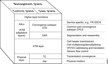
The physical layer is divided into two parts:
The ATM layer processes ATM cells. The ATM cell consists of a 5-byte header and a 48-byte payload. The header contains the ATM cell address and other management information as shown in Figure C-2.

Two basic header types are defined by the standards committees, a UNI header and a NNI header; both are quite similar. Cisco has expanded on these header types to provide additional features beyond those proposed for basic ATM service.
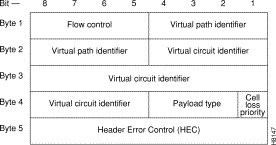
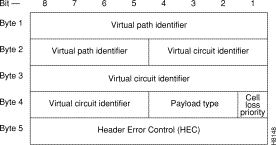
The most important fields in all three ATM cell header types are:
The VPI and VCI are translated at each ATM switch, they are unique only for a given physical link.
A 4-bit Generic Flow Control (GFC) field in the UNI header is intended to be used for controlling user access and flow control. At present, it is not defined by the standards committees and is generally set to all zeros.
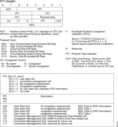
A 3-bit Payload Type Indicator (PTI) field indicates the type of data being carried in the payload. The high-order bit is a "0" if the payload contains user information and is a "1" if it carries connection management information. The second bit indicates if the cell experienced congestion over a path. If the payload is user information, the third bit indicates if the information is from Customer Premises Equipment. The PTI field is identical for UNI/NNI/STI.
In the STI header (see ), the Payload Class is used to indicate various classes of service and BPX switch queues, such as Opticlass, the enhanced class of service feature of the BPX switch. The ForeSight Forward Congestion Indication, the F bit, is used by ForeSight for congestion status.
The Cell Loss Priority (CLP) bit follows the PTI bits in all header types. When set, it indicates that the cell is subject to discard if congestion is encountered in the network. For Frame Relay connections, depending on mapping considerations, the frame Discard Eligibility status is carried by the CLP bit in the ATM Cell. The CLP bit is also set at the ingress to the network for all cells carrying user data transmitted above the minimum rate guaranteed to the user.
Each ATM cell contains a two-part address, VPI/VCI, in the cell header. This address uniquely identifies an individual ATM virtual connection on a physical interface. VCI bits are used to identify the individual circuit or connection. Multiple virtual circuits that traverse the same physical layer connection between nodes are grouped together in a virtual path. The virtual path address is given by the VPI bits. The Virtual Path can be viewed as a trunk that carries multiple circuits all routed the same between switches
The VPI and VCI addresses may be translated at each ATM switch in the network connection route. They are unique only for a given physical link. Therefore, they may be reused in other parts of the network as long as care is taken to avoid conflicts.
The VCI field is 16 bits wide with UNI and NNI header types described earlier. This allows for a total possible 65, 535 unique circuit numbers. The UNI header reserves 8 bits for VPI (256 unique paths) while the NNI reserves 12 bits (4,096 unique paths) as it is likely that more virtual paths will be routed between networks than between a user and the network. The STI header reserves 8 bits for VCI and 10 bits for VPI addresses.
The purpose of the ATM Adaptation Layer (AAL) is to receive the data from the various sources or applications and convert, or adapt, it to 48-byte segments that will fit into the payload of an ATM cell. Since ATM benefits from its ability to accommodate data from various sources with differing characteristics, the Adaptation Layer must be flexible.
Traffic from the various sources have been categorized by the standards committees into four general classifications, Class A through Class D, as indicated in Table C-1. This categorization is somewhat preliminary and initial developments have indicated that it may be desirable to have more than these initial four classes of service.
| Traffic Class | Class A | Class B | Class C | Class D |
|---|---|---|---|---|
Adaptation Layer (AAL) | AAL-1 | AAL-2 | AAL-3/4 AAL-5 | AAL-3/4 |
Connection Mode | Connection-oriented | Connection-oriented | Connection-oriented | Connectionless |
End-to-End Timing Relationship | Yes | Yes | No | No |
Bit Rate | Constant | Variable | Variable | Variable |
Examples | Uncompressed voice, constant bit-rate video | Compressed voice and video | Frame relay, SNA, TCP-IP, E-mail | SMDS |
Initially, four different adaptation layers (AAL1 through AAL4) were envisioned for the four classes of traffic. However, since AAL3 and AAL4 both could carry Class C as well as Class D traffic and since the differences between AAL3 and AAL4 were so slight, the two have been combined into one AAL3/4.
AAL3/4 is quite complex and carries a considerable overhead. Therefore, a fifth adaptation layer, AAL5, has been adopted for carrying Class C traffic, which is simpler and eliminates much of the overhead of the proposed AAL3/4. AAL5 is referred to as the Simple and Efficient Adaptation Layer, or SEAL, and is used for Frame Relay data.
Since ATM is inherently a connection-oriented transport mechanism and since the early applications of ATM will be heavily oriented towards LAN traffic, many of the initial ATM products are implemented supporting the Class C Adaptation Layer with AAL5 Adaptation Layer processing for carrying Frame Relay traffic.
Referring back to Figure C-1, the ATM Adaptation Layer consists of two sub-layers:
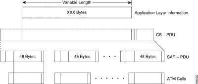
Data is received from the various applications layers by the Convergence Sub-Layer and mapped into the Segmentation and Reassembly Sub-Layer. User information, typically of variable length, is packetized into data packets called Convergence Sublayer Protocol Data Units (CS-PDUs). Depending on the Adaptation Layer, these variable length CS-PDUs will have a short header, trailer, a small amount of padding, and may have a checksum.
The Segmentation and Reassembly Sub-Layer receives the CS-PDUs from the Convergence Sub-Layer and segments them into one or more 48-byte SAR-PDUs, which can be carried in the 48-byte ATM information payload bucket. The SAR-PDU maps directly into the 48-byte payload of the ATM cell transmitted by the Physical Layer. Figure C-6 illustrates an example of the Adaptation Process.
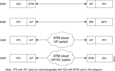
The IGX switch connects to an ATM trunk via the UXM card. The BTM (IGX switch) can operate in several different addressing modes that you can select (see Table C-2 and Figure C-7):
| Addressing Mode | Hdr. Type | Derivation of VPI/VCI | Where Used |
|---|---|---|---|
BAM-BPX switch Addressing Mode | STI | VPI/VCI = Node Derived Address | Between IGX switch and BPX switches, or between IGX switch nodes. |
CAM— | UNI | VPI = User Programmed | IGX switch to IGX switch connections over networks using ATM switches that switch on VPI only. VPI is manually programmed by user. Terminating switch converts VCI address to FastPacket address. |
SAM— | UNI | VPI/VCI = User Programmed | IGX switch to IGX switch connections over networks using ATM switches that switch where all routing is manually programmed by user, both VPI and VCI. |
A specialized adaptation of particular interest to users of Cisco equipment is the adaptation of IPX switch FastPackets to ATM cells. A large number of narrowband IPX switch networks currently in existence efficiently carry voice, video, data, and Frame Relay. A means must be provided to allow these networks to grow by providing a migration path to broadband.
Because FastPackets are already a form of cell relay, the adaptation of FastPackets to ATM cells is relatively simple.
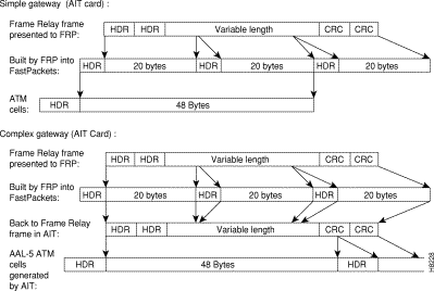
With the Simple Gateway protocol, the AIT card in the IPX switch (or BTM in the IGX switch) loads 24-byte FastPacket cells into ATM cells in ways that are consistent with each application. (Each of the two FastPacket cells loaded into the ATM Cell is loaded in its entirety, including the FastPacket header.) For example, two FastPackets can be loaded into one ATM cell provided they both have the same destination. This adaptation is performed by the IPX switch AIT card or the IGX switch BTM card.
The AIT (or BTM) is configured to wait a given interval for a second FastPacket to combine in one ATM cell for each FastPacket type. The cell is transmitted half full if the wait interval expires. High priority and non-time stamped packets are given a short wait interval. High priority FastPackets will not wait for a second FastPacket. The ATM trunk interface will always wait for Frame Relay data (bursty data) to send two packets. NPC traffic will always have two FastPackets in an ATM cell.
Starting with Release 8.1, with the Complex Gateway capability, the FRSM card in the MGX 8220, the AIT card in the IPX switch (or BTM card in the IGX switch) streams the Frame Relay data into ATM cells, cell after cell, until the frame has been completely transmitted. Since only the data from the FastPacket is loaded, the Complex Gateway is an efficient mechanism. Also, discard eligibility information carried by the Frame Relay bit is mapped to the ATM cell CLP bit, and vice versa. See Chapter 13 for further information on Frame Relay to ATM interworking. A comparison of the simple gateway and complex gateway formats is shown in Figure C-8.
![]()
![]()
![]()
![]()
![]()
![]()
![]()
![]()
Posted: Fri Jul 27 16:48:41 PDT 2001
All contents are Copyright © 1992--2001 Cisco Systems, Inc. All rights reserved.
Important Notices and Privacy Statement.