|
|

This chapter describes Broadband Switch Module (BXM) virtual trunks, a feature supported by the BXM cards beginning with switch software Release 9.2:
Note: Virtual trunking is a purchased feature; Cisco Customer Service must enable it on each node where you intend to use virtual trunking.
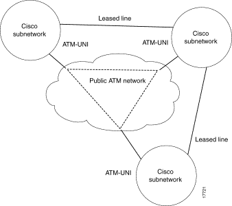
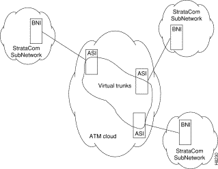
Virtual trunking provides connectivity for Cisco switches through a public ATM cloud as shown in Figure 25-1. Because a number of virtual trunks can be configured across a physical trunk, virtual trunks provide a cost effective means of connecting across a public ATM network. Each virtual trunk typically uses only part of a physical trunk's resources. Yet, like regular trunks, virtual trunks can carry high-priority traffic.
The hybrid network configuration provided by virtual trunking allows private virtual trunks to use the mesh capabilities of the public network in interconnecting the subnets of the private network.
A virtual trunk is simply "a trunk defined over a public ATM service." The trunk really does not exist as a physical line in the network. You use an additional level of reference, called a virtual trunk number, to differentiate the virtual trunks found within a physical port.
You establish connectivity through a public ATM cloud by allocating virtual trunks between the nodes on the edge of the cloud. With only a single trunk port attached to a single ATM port in the cloud, a node uses the virtual trunks to connect to multiple destination nodes on the other side of the cloud. From the perspective of a Cisco node, a virtual trunk is equivalent to a VPC provided by the ATM cloud network, which provides connectivity through the cloud.
The ATM equipment in the cloud must support Virtual Path switching and moving incoming cells based on the VPI in the cell header. Within the cloud, one virtual trunk is equivalent to one VPC. Because the VPC is switched with just the VPI value, the 16 VCI bits (from the ATM cell format) of the ATM cell header are passed transparently through to the other end. The VCI bits within the header are passed transparently through the entire cloud (see Figure 25-1). The virtual path ID (VPI) is provided by the ATM cloud administrator (for example, service provider).
The BXM card's physical trunk interface to the ATM cloud is a standard ATM UNI or NNI interface at the cloud's access point. The administrator of the ATM cloud (such as, Service Provider) specifies whether the interface is UNI or NNI, and also provides the VPI to be used by a virtual trunk across the cloud. Specifying an NNI cell interface provides 4 more bits of VPI addressing space.
There are two general types of virtual trunks:
With the BPX switch, you can set up virtual networks with either the Broadband Network Interface (BNI) card or with the BXM card. The virtual trunks originate and terminate on:
When the Cisco network port is a BXM accessing a port in the Public ATM network, the Public ATM port may be a UNI or NNI port on a BXM or other standards-compliant UNI or NNI port.
When the Cisco network port is a BNI accessing a port in the Public ATM network, the Public ATM port must be a port on a BPX.
Figure 25-1 shows three Cisco WAN switching networks, each connected to a Public ATM Network via a physical line. The Public ATM Network is shown linking all three of these subnetworks to every other one with a full meshed network of virtual trunks. In this example, each physical line is configured with two virtual trunks.
Virtual trunking benefits include:
The BXM card provides several combinations of numbers of VIs, ports, and channels as listed in Table 25-1, depending on the specific BXM card.
 |
Note A virtual trunk cannot be used as a feeder trunk. Feeder connections cannot be terminated on a virtual trunk. |
| Number of VIs | Max LCNs | Default LCNs | |
|---|---|---|---|
BXM | 31 | 32000 | 16320 |
This syntax describes a virtual trunk:
UXM/BXM:slot.port.vtrunk
slot = slot number (1-32) Keep in mind that on the BPX slots 7 and 8 are reserved for BCCs and slot and 15 is reserved for the ASM card.
port = port number (1-16)
vtrunk = virtual trunk number (1-31 on BXM) (1-15 on UXM)
These three principles define card capacities for virtual trunking:
For example, the BXM supports 31 virtual interfaces and therefore up to 31 virtual trunks may be defined within one port.
Thus maximum capacities are:
Trunk redundancy refers to one of two features:
ATM trunk redundancy is the T3 and E3 trunk redundancy supported by the AIT, ALM/B, and BTM cards. Redundancy can exist between either:
Virtual trunking and trunk redundancy are incompatible. Trunk redundancy uses the standard trunk cables rather than a Y-cable. (For all service card sets other than trunk cards, you manage redundancy by using the Y-cable redundancy commands addyred, delyred, prtyred, and dspyred).
Trunk redundancy depends on the applicable commands, the trunk card in the adjacent slot, and the standard trunk cable. You can execute trunk redundancy commands only on the IGX node.
The BPX node does not require information regarding this feature.
In Figure 25-2, three virtual trunks 4.1.1, 4.1.2, and 4.1.3 are shown configured on a physical trunk that connects to the port 4.1 interface of a BXM. Also, a single trunk is shown configured on port 4.2 of the BXM. In this example, four VIs have been used, one each for virtual trunks 4.1, 4.2, and 4.3, and one for physical trunk 4.2.
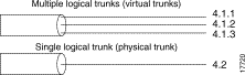
Each logical trunk, whether physical or virtual is assigned a virtual interface when it is activated.
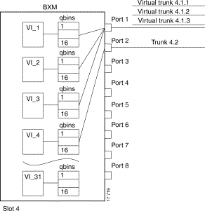
A BXM card has 31 possible egress virtual interfaces. Each of these interfaces in turn has 16 qbins assigned to it.
In the example in Figure 25-3, port 1 has three virtual trunks (4.1.1, 4.1.2, and 4.1.3), each of which is automatically assigned a virtual interface (VI) with the VI's associated 16 qbins. Port 2 is shown with a single physical trunk (4.2) and is assigned a single VI.
On a 1-port BXM-622 card, for example, up to 31 virtual interfaces can be used on the port corresponding to 31 virtual trunks. On an 8-port BXM 155 card, for example, the 31 VIs would be distributed to the active trunks, standard or virtual. If trunks were activated on all eight ports, the maximum number of VIs which can be assigned to one port is 24 (31 less 1 for each of the other 7 trunks activated on the card).
AutoRoute connections use qbins 0 through 9.
Virtual Switch Interfaces (VSIs), which support master controllers use qbins 10 through 15, as applicable. The BXM can concurrently support MPLS and AutoRoute, or PNNI and AutoRoute, or MPLS and PNNI at the same time on a given VSI.
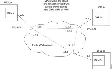
An example of a number of virtual trunks configured across a Public ATM Network is shown in Figure 25-4. There are three virtual trunks shown across the network, each with its own unique VPC.
The three virtual trunks shown in the network are:
Each VPC defines a virtual trunk that supports the traffic types shown in Table 25-2.
AutoRoute, PNNI, and MPLS each use different routing mechanisms. However, the routing mechanisms meet the following criteria when dealing with virtual trunks:
The characteristics of a virtual trunk used by connection routing are maintained throughout the network. This information—virtual trunk existence, traffic classes and connection channels—is sent to every node to allow the routing algorithm to use the trunk correctly. Routing uses only those virtual trunks that can support the traffic type of the connection.
Virtual trunking is supported by these features:
The cell addressing method for connections routed through a virtual trunk handles multiple type of traffic flowing through an ATM cloud. The header format of cells may match the ATM-UNI or ATM-NNI format because the port interface to the ATM cloud is a physical configured as either a UNI or NNI interface, as specified by the administrator of the ATM cloud.
Cells transmitted to a virtual trunk use the standard UNI or NNI cell format.
Before cells enter the cloud on a virtual trunk, the cell header is translated to a user configured VPI value for the trunk, and a software configured VCI value which is unique for the cell. The trunk card at the edge of the cloud ensures that cells destined for a cloud VPC have the correct VPI/VCI.
As cells are received from the cloud by the BPX or IGX in the Cisco networks at the other end of the cloud, these VPI/VCIs are mapped back to the appropriate VPI/VCI addresses by the Cisco nodes for forwarding to the next destination.
The VPI is an 12-bit value ranging from 1 through 4095. The VCI is a 16-bit value ranging from 1 through 65535.
The VPI value across the virtual trunk is identical for all cells on a single virtual trunk. The VCI value in these cells determines the final destinations of the cells. On BNI cards, for virtual trunking a modified ATM UNI cell format (Strata-UNI) stores the ForeSight information, as applicable, in the header of a Strata-UNI cell format. A virtual trunk with a BNI at one end must terminate on a BNI at the other end.
Figure 25-5 shows three different cell header types, ATM-STI, ATM-UNI, and Strata-UNI through a cloud. The ATM-NNI header which is not shown, differs in format from the ATM-UNI only in that there is no GFCI field and those four bits are added to the VPI bits to give a 12-bit VPI.
The ATM-STI header is used with BNI trunks between BPX nodes within a Cisco switch subnetwork. The ATM-UNI is the standard ATM Forum UNI supported by the BXM card along with standard NNI. Virtual trunks terminating on BXMs or UXMs use the standard ATM-UNI or ATM-NNI header as specified by the cloud administrator (such as, Service Provider). Virtual trunks terminating on BNIs use the Strata-UNI header.
Because the BNI cards use a Strata-UNI format across a virtual trunk, BNI virtual trunks are not compatible with BXM/UXM virtual trunks which use either the standard UNI or NNI cell header formats. Therefore, BXM to BXM, UXM to UXM, and BXM to UXM virtual trunks are supported, while BNI to BXM or BNI to UXM virtual trunks are not supported.
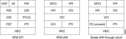
The ATM-STI header uses four of the VPI bit spaces for additional control information. When the cell is to be transferred across a public network, a shift of these bit spaces is performed to restore them to their normal location so they can be used across a network expecting a standard header.
This bit shifting is shown in Table 25-2. A BNI in the Cisco subnetwork can interface to a BXM (port configured for port mode) in the cloud. The BXM in the cloud is configured for no shift in this case.
A BXM in the Cisco subnetwork can interface to a BXM UNI port or other UNI port in the cloud. The BXM in the cloud is configured for bit shifting as shown in Table 25-2.
| Subnetwork | FW Rev | Shift | Cloud | FW Rev | Shift | |
|---|---|---|---|---|---|---|
BXM | -- |
| > | BXM (port mode) |
| Yes** |
BNI | -- |
| > | BXM (port mode) |
| No |
The total bandwidth of all the virtual trunks in one port cannot exceed the maximum bandwidth of the port. The trunk loading (load units) is maintained per virtual trunk, but the cumulative loading of all virtual trunks on a port is restricted by the transmit and receive rates for the port.
The total number of connection channels of all the virtual trunks in one port cannot exceed the maximum number of connection channels of the card. The number of channels available is maintained per virtual trunk
All cells transmitted to a virtual trunk have a translated cell address. This address consists of a VPI chosen by the user and a VCI (ConId) chosen internally by the software. The trunk firmware is configured by the software to perform this translation.
The user-chosen VPI is the same for all cells on a virtual trunk.
At the receiving end, multiple virtual trunks can send cells to one port. The port must be able to determine the correct channel for each of these cells.
The VPI is unique on each trunk for all the cells, but the VCI may be the same across the trunks. Each port type has a different way of handling the incoming cell addresses. Only the BXM and UXM are discussed here.
For connections, the associated LCNs are selected from a pool of LCNs for the entire card. Each virtual trunk can use the full range of acceptable conid values. The range consists of all the 16-bit values (1 through 65535) excluding the node numbers and blind addresses. A port uses the VPI to differentiate connections which have the same conid.
You can change the number of channels per virtual trunk once the trunk has been added to the network. Decreasing the number of channels on an added virtual trunk will cause connection reroutes whereas increasing the number of channels on an added virtual trunk will NOT cause connection reroutes.
A VPC is not allowed to be routed over a virtual trunk. The routing algorithm excludes all virtual trunks from the routing topology. The reason for this restriction is due to how the virtual trunk is defined within the ATM cloud.
The cloud uses a VPC to represent the virtual trunk. Routing an external VPC across a virtual trunk would consist of routing one VPC over another VPC. This use of VPCs is contrary to its standard definition. A VPC should contain multiple VCCs, not another VPC. In order to avoid any non-standard configuration or use of the ATM cloud, VPCs cannot be routed over a virtual trunk through the cloud.
In order for the virtual trunk to successfully move data through an ATM cloud, the cloud must provide some form of connectivity between the trunk endpoints. The ATM equipment in the cloud must support virtual path switching and move incoming cells based on the VPI in the cell header.
A virtual path connection (VPC) is configured in the cloud to join two endpoints. The VPC can support either CBR, VBR, or ABR traffic. A unique VP ID per VPC is used to moved data from one endpoint to the other. The BPX nodes at the edge of the cloud send in cells which match the VPC's VPI value. As a result the cells are switched from one end to the other of the ATM public cloud.
Within the ATM cloud one virtual trunk is equivalent to one VPC. Since the VPC is switched with just the VPI value, the 16 VCI bits (from the ATM cell format) of the ATM cell header are passed transparently through to the other end.
If the public ATM cloud consists of BPX nodes using BXM cards, the access points within the cloud are BXM ports. If the cloud consists of IGX nodes, the access points within the cloud are UXM ports.
The two ends of a virtual trunk can have different types of port interfaces. For example, a virtual trunk may contain a T3 port at one end of the ATM cloud and an OC-3 port at the other end.
However, both ends of the trunk must have the same bandwidth, connection channels, cell format, and traffic classes. This requirement is automatically checked during the addition of the trunk.
All types of traffic from a private network using Cisco nodes are supported through a public ATM cloud. The CBR, VBR, and ABR configured virtual trunks within the cloud should be configured to carry the correct type of traffic.
A CBR configured trunk is best suited to carrying delay sensitive traffic such as voice/data, streaming video, and ATM CBR traffic, and so on.
A VBR configured trunk is best suited to carrying frame relay and VBR traffic, and so on.
An ABR configured trunk is best suited to carrying ForeSight and ABR traffic, and so on.
Two-stage queueing at the egress of virtual trunks to the ATM cloud allows shaping of traffic before it enters the cloud. However, the traffic is still routed on a single VPC and may be affected by the traffic class of the VPC selected.
You can configure any number of virtual trunks up to the maximum number of virtual trunks per slot (card) and the maximum number of logical trunks per node. These trunks can be any of the three trunk types, CBR, VBR, or ABR.
You can configure any number of virtual trunks between two ports up to the maximum number of virtual trunks per slot and the maximum number of logical trunks per node. These trunks can be any of the three trunk types.
In the BXM, the egress cell traffic out a port is queued in 2 stages:
In other words, these types of traffic are queued separately:
AutoRoute |
|
|
| voice |
|
| time-stamped |
|
| non time-stamped |
|
| high-priority |
|
| bursty data A (bdataA) |
|
| bursty data B (bdataB) |
|
| cbr |
|
| vbr |
|
| abr |
|
VSI |
|
|
| MPLS Classes of Service |
|
| UBR |
|
| PNNI traffic |
|
These classes are all queued separately, and the overall queue depth of the virtual interface is the sum of all the queue depths shared by all the available queues. Because each virtual trunk occupies one virtual interface (VI), the overall queue depth available for the virtual trunk is that of its VI.
You do not directly configure the VI.
You use the cnftrkparm command to configure the queues within AutoRoute virtual trunks.
You use the cnfvsiif and cnfqbin commands to configure the queues within VSI virtual trunk VIs.
Before setting up a trunk, you must first finish setting up the nodes. Also, the front and back cards that support the proposed line type and communication technology must reside in the slot intended for the trunk.
The Ports and Trunks feature allows you to configure port, routing trunk and feeder trunk interfaces simultaneously on a slot containing a BXM or UXM card. For example, you can up port 1 on a BXM slot as a trunk interface while also upping port 2 as a line interface. For BXM and UXM cards, you do not need to upgrade the firmware.
You cannot use a virtual trunk as an interface shelf (feeder) trunk; similarly, you cannot configure an interface shelf trunk to act as a virtual trunk. Similarly, you cannot terminate interface shelf (feeder) connections on a virtual trunk.
| Interface Type | BXM | UXM |
|---|---|---|
|
|
|
|
|
|
|
|
|
|
|
|
To setup a trunk:
Use the uptrk command to activate the port so that it can start to generate framing. It also determines whether the trunk is a physical-only trunk or a virtual trunk. The third digit you specify in the uptrk command (represented by slot.port.vtrk) indicates that the trunk is virtual.
Use uptrk at each end of the trunk. When the trunk is upped at only one end, the node detects the trunk as being in an alarm state (see dsptrks). Upping the trunk at both ends clears the alarm.
Step 2 Use the cnftrk command to override the trunk's default values. You must use cnftrk for virtual trunks, but it is an optional command for physical trunks. For virtual trunks, you must change the VPI to a non-0 value before executing addtrk.
If you use cnftrk, you must make the same changes at both ends of the trunk. To display existing trunk parameters, use the dsptrkcnf command. The configurable parameters are listed for each card type in Table 25-3. (The possible parameters are PKT for FastPackets, ATM cells, BNI if the trunk is a BNI card, or All.) Not all of these parameters apply to the BPX node.
Step 3 Use addtrk to add the trunk. Adding the trunk makes the trunk a usable resource, so you can add connections (addcon) to carry traffic. You need to add only one end of the trunk.
After you configure the trunk, and add the trunk (addtrk), you can re-specify certain parameters. For example, a period of trunk use may give you enough information to indicate that you should change parameters to optimize how the trunk is used.
The following example is a general procedure on how to set up a virtual trunk through an ATM cloud using Cisco equipment (that is, a BPX or IGX cloud).
Step 2 Set up cables by doing the following: in the cloud network, physically connect a BXM port to each BNI port that is likely to carry virtual trunks.
Step 3 For each port connected to a BNI virtual trunk port, use the following configuration sequence:
The Shift/No shift parameter specifies whether or not the VCI bits in the cell header should be shifted based on the HCF field of the cell header on cells arriving from the backplane. It is how Cisco networks convert STI cells to standards based cell formats, and similarly how standards-based cell formats are converted back to STI cells.
Step 4 Execute addcon. In the cloud network, add a virtual path connection for each end of the virtual trunk that is to be routed through the cloud. An example of the syntax for this is:
addcon joker 5.1.1.* swstorm 6.2.10.*
where 5.1 and 6.2 are ports that are hooked up and configured for virtual trunking. DACS connections are acceptable.
Note that the third number is the VPI, which must correspond to the virtual trunk VPI configured with cnftrk in step 4. For BNI virtual trunks, the useable range of VPIs is 1 to 255 (for T3/E3 trunks). For BNI OC-3 virtual trunks, the useable range of VPIs is 1-63.
The VPI configured for a virtual trunk must match the VPI of the VPC in the public ATM cloud. Every cell transmitted to the virtual trunk has this VPI value. Valid VPC VPIs depend on the port type as shown in Table 25-5.
| Port Type | Valid VPI Range |
|---|---|
BXM/UXM (UNI) | 1-255 |
BXM/UXM (NNI) | 1-4095 |
BNI T3/E3 | 1-255 |
BNI OC-3 | 1-63 |
The CBR/VBR parameter must also correspond to the virtual trunk type of the virtual trunk. For T3, set PCR to 96000 and CDTV to 24000 for the connection so that the does not drop cells. Cisco recommends these values based on testing.
Step 5 Configure BNI trunks. Use uptrk to enable the virtual trunk on the port. Take this step if the ATM cloud provider has assigned the VPC. On BNIs that connect to the cloud's ports, configure the virtual trunks, as follows:
If the cloud is already configured, the alarm on the virtual trunk should clear.
When you use cnftrk to configure the virtual trunk, make sure the virtual trunk type and VPI correspond to the existing Virtual Path connections (that is, make sure that the virtual trunk matches the cloud's VPC configuration, uses the correct cell format (UNI or NNI), and that HCF-based shifting is off (which you configure using cnfport on the port).
Step 6 Use addtrk to add the virtual trunk to the network topology.
The parameters slot.port.vtrk on a BNI card can have the following values:
This example is a general explanation of how to set up a virtual trunk through a BPX or IGX cloud:
Step 2 Set up cables by doing the following: in the cloud network, physically connect a BXM port to each BXM port that is likely to carry virtual trunks.
Step 3 For each port connected to a BXM virtual trunk port, use the following configuration sequence:
The Shift/No shift parameter specifies whether or not the VCI bits in the cell header should be shifted based on the HCF field of the cell header on cells arriving from the backplane. It is how Cisco networks convert STI cells to standards based cell formats and similarly how standards-based cell formats are converted back to STI cells. See Table 25-6 for some general guidelines on how to set the Shift parameter when using virtual trunking through a cloud of non-Cisco equipment versus Cisco equipment using BXMs.
If the network has BNI cards, or if the VPC can route over BNIs, set the cnfport Shift parameter to "H". This causes the cell, when transported over a public network, to shift these bit spaces to restore them to their normal location that they can be used across a network expecting a standard ATM cell header. If, however, the route through the cloud traverses all BXMs, for example, then configure the cnfport command to No shift (on the port's entry point into the cloud).
For UXM cards, you cannot configure the Shift parameter—the Shift setting is always N, or Shift off.
| Non-Cisco Cloud | Cisco BXM Cloud | |
|---|---|---|
BNI Virtual Trunks | Shift off | Shift off |
BXM/UXM Virtual Trunks | Shift off | Shift on |
Step 4 Execute addcon. In the cloud network, add a virtual path connection for each end of the virtual trunk that is to be routed through the cloud. An example of the syntax for this is:
where 5.1 and 6.2 are ports that are hooked up and configured for virtual trunking. DACS connections are acceptable.
Note that the third number is the VPI, which must correspond to the virtual trunk VPI configured with cnftrk in step 4. For UXM/BXM UNI virtual trunks, the useable range of VPIs is 1 to 255. For UXM/BXM NNI virtual trunks, the useable range of VPIs is 1-4095.
The CBR/VBR parameter must also correspond to the virtual trunk type of the virtual trunk. For T3, set PCR to 96000 and CDTV to 24000 for the connection so that the BXM does not drop cells. Cisco recommends these values based on testing.
Step 5 Configure BXM trunks. Use uptrk to enable the virtual trunk on the port. Take this step if the ATM cloud provider has assigned the VPC. On BXMs that connect to the cloud's ports, configure the virtual trunks, as follows:
If the cloud is already configured, the alarm on the virtual trunk should clear.
When you use cnftrk to configure the virtual trunk, make sure the virtual trunk type and VPI correspond to the existing Virtual Path connections (that is, make sure that the virtual trunk matches the cloud's VPC configuration, uses the correct cell format (UNI or NNI), and that HCF-based shifting is Shift on.)
Ports on UXM cards that connect to a cloud must always be set to Shift off.
Connections between a port set to Shift on and a port set to Shift off are not guaranteed.
Step 6 Optionally, use cnfrsrc to configure the number of connection IDs (conids) and the bandwidth available on the trunk. (Refer to the cnfrsrc command in this chapter.)
Step 7 Use addtrk to add the virtual trunk to the network topology.
The parameters slot.port.vtrk on a BXM card can have the following values:
BXM cards support up to 31 virtual trunks, while UXM cards support up to 15 virtual trunks.
The two ends of a virtual trunk can have different port interfaces. For example, a virtual trunk supported by a UXM-OC-3 on one end can be supported by a BXM-T3 at the other end.
However, both ends of the trunk must have the same:
The addtrk command verifies this when you add the trunk.
The procedure in this section gives the specific commands for every step in adding one virtual trunk across an ATM network. This is a very typical situation.
This procedures assumes this hypothetical situation:
Given this situation, you would perform these steps:
1. Initial Setup |
| Contact Customer Service to enable virtual trunking on the nodes in your network. |
2. In the public ATM cloud |
| Obtain the VPCs for the virtual trunks for the service provider. These are the VPCs that are configured within the ATM cloud by the service provider to support the virtual trunks. |
3. At BPX_A | uptrk 4.3.1 uptrk 4.3.2 | Up virtual trunks 4.3.1 and 4.3.2 on BXM port 4.3. |
4. At BPX_A | cnftrk 4.3.1 ... cnftrk 4.3.2 ... | Configure the virtual trunks to match the cloud's VPC configuration, including: VPI, header type (UNI or NNI), traffic classes, and VPC type, and so on. |
5. At BPX_A | cnfrsrc 4.3.1 ... cnfrsrc 4.3.2 ... | Configure the number of conids, bandwidth, and so on, available for the virtual trunks. |
6. At BPX_B | uptrk 5.1.1 uptrk 5.1.2 | Up virtual trunks 5.1.1 and 5.1.2 on BXM port 5.1. |
7. At BPX_B | cnftrk 5.1.1 ... cnftrk 5.1.2 ... | Configure the virtual trunks to match the cloud's VPC configuration, including: VPI, header type (UNI or NNI), traffic classes, and VPC type, and so on. |
8. At BPX_B | cnfrsrc 5.1.1 ... cnfrsrc 5.1.2 ... | Configure the number of conids, bandwidth, and so on., available for the virtual trunks. |
9. At IGX_A | uptrk 10.2.1 uptrk 10.2.3 | Up virtual trunks 10.2.1 and 10.2.3 on IGX trunk port 10.2. |
10. At IGX_A | cnftrk 10.2.1 ... cnftrk 10.2.3 ... | Configure the virtual trunks to match the cloud's VPC configuration, including: VPI, header type (UNI or NNI), traffic classes, and VPC type, and so on. |
11. At IGX_A | cnfrsrc 10.2.1 ... cnfrsrc 10.2.3 ... | Configure the number of conids, bandwidth, and so on, available for the virtual trunk. |
12. At BPX_A | addtrk 4.3.1 IGX_A 10.2.1 addtrk 4.3.2 BPX_B 5.1.1 | Add the virtual trunks between three nodes. Using addtrk 10.2.1 ... at IGX_A and addtrk 5.1.1 ... at BPX_B would also add the virtual trunks. |
13. At BPX_B | addtrk 5.1.2 IGX_A 10.2.3 | Add the virtual trunks between the two nodes. Using addtrk 10.2.3 ... at IGX_A would also add the virtual trunks. |
The VPI values you choose by using cnftrk must match those used by the cloud VPC.
In addition, both ends of the virtual trunk must match with respect to:
Use the addtrk command to check for matching values before allowing the trunk to be added to the network topology.
The network topology as seen from a dsptrks command at BPX_A would be:
BPX_A 4.3.1-10.2.1/IGX_A
BPX_A 4.3.2-5.1.1/BPX_B
This section is a general procedure for setting up a virtual trunk.
Virtual trunking is an optional feature that must be enabled by Cisco prior to adding virtual trunks. Also, revision levels of BNI firmware must be current.
This procedure assumes that Cisco equipment is used in the ATM Cloud as well as in the Cisco WAN Switching subnetworks. In this case, a BNI output from the subnetwork is connected to a UNI input at the ATM Cloud (see Figure 25-7).
Step 2 Configure the cloud ports. For each port connected to a BNI virtual trunk port, run these commands:
Where 5.1 and 6.2 are ports hooked up and configured for virtual trunking. Daxcons are acceptable.
Note that the third number is the VPI which must correspond to the virtual trunk VPI you configured by using cnftrk in Step 4.
When the cloud is a public ATM service and not a Cisco WAN Switching cloud, the VPI is provided by the carrier, as well as the guaranteed BW associated with the VPI.
The Constant Bit Rate (CBR), Variable Bit Rate (VBR), and Available Bit Rate (ABR) parameters must also correspond to the Virtual Trunk Type of the virtual trunk. For T3, set PCR to the bandwidth of the virtual trunk, and CDVT to 24000 for the connection so that the card does not drop cells. These are values that Cisco recommends based on testing.
Step 3 Configure the Broadband Network Interface (BNI) virtual trunks. On the BNIs that connect to the cloud ports, configure up to 32 virtual trunks:
For cnftrk, make sure that the virtual trunk type and the VPI correspond to the Virtual Path connections that have been set up.
The command summarized here are specific to virtual trunk usage on the BPX, using the BXM cards. For complete information about each these commands, refer to the Cisco WAN Switching Command Reference and Cisco WAN Switch SuperUser Command Reference.
For information about the UXM, refer to the IGX 8400 Series documents. Also, refer to the Cisco WAN Manager documents for application information using a graphical user interface for implementing command functions.
The primary commands used for configuration of virtual trunks are:
The main parameters for cnftrk are:
The VPI configured for a virtual trunk must match the VPI of the VPC in the public ATM cloud. Every cell transmitted to the virtual trunk has this VPI value. Valid VPC VPIs depend on the port type as shown in Table 25-7
| Port Type | Valid VPI Range |
|---|---|
BXM/UXM (UNI) | 1-255 |
BXM/UXM (NNI) | 1-4095 |
BNI T3/E3 | 1-255 |
BNI OC-3 | 1-63 |
Use cnfrsrc to configure conids (lcns) and bandwidth. The conid capacity indicates the number of connection channels on the trunk port which are usable by the virtual trunk.
This number cannot be greater than the total number of connection channels on the card. The maximum number of channels is additionally limited by the number of VCI bits in the UNI cell header.
For a virtual trunk, the number is divided by the maximum number of virtual trunks on the port to determine the default. You configure this value by using the cnfsrc command on the BPX.
Table 25-8 lists the number of connection ids for virtual trunks on various cards.
| Port Type | Maximum Conids | Default |
|---|---|---|
BXM/UXM | 1-(number of channels on the card) | 256 |
BNI T3/E3 | 1-1771 | 256 |
BNI OC-3 | 1-15867 (3837 max/vtrk | 256 |
cnftrkparm
BXM and UXM virtual trunks have all the configuration parameters for queues as physical trunks.
The integrated alarm thresholds for major alarms and the gateway efficiency factor is the same for all virtual trunks on the port.
Note that BNI VTS are supported by a single queue and do not support configuration of all the OptiClass queues on a single virtual trunk.
When a physical port attribute change is made, you are notified that all trunks on the port are affected.
Virtual trunks support APS redundancy on BXM OC-3 and OC-12 ports. For more information, refer to the section on APS Redundancy in this manual. You configure this by using primarily these commands:
The prior Y-redundancy is not supported by virtual trunks, nor the related commands, addtrkred, deltrkred, and dsptrkred.
Because a virtual trunk is defined within a trunk port, its physical characteristics are derived form the port. All the virtual trunks within a port have the same port attributes.
If a physical trunk is specified on a physical port that supports multiple virtual trunks, the command is applied to all virtual trunks on the physical port.
If a virtual trunk is specified for a command that configures information related to the physical port, then the physical port information is configured for all virtual trunks.
With Release 9.2, the BPX statistics organization separates logical and physical trunk statistics. This is also the method used on the UXM card on the IGX 8400 series switches.
The following commands are available on both the IGX and the BPX and have the same results. Refer to the IGX 8xxx Series documentation for information the IGX and UXM.
The entries in Table 25-9 that are marked with a [*} are configured on a logical trunk basis, but automatically affect all trunks on the port when a physical option is changed. For example, if the line framing is changed on a virtual trunk, all virtual trunks on the port are automatically updated to have the modified framing.
| Command | Description |
|---|---|
addtrk | adds a trunk to the network |
ckrtrkerrs | clears the trunk errors for a logical trunk |
clrtrkstats | clears the summary trunk statistics for a logical trunk |
clrphyslnerrs | clears trunk errors for a physical line |
cnflnalm | configures the statistical alarm thresholds for trunks and ports (affects all trunks on node) |
cnftrk | configures a logical trunk [*] |
cnftrkparm | configures the trunk parameters of a logical trunk [*] |
cnftrkstats | configures the interval statistics collection for a logical trunk |
cnfphyslnstats | configures the interval statistics for a physical line |
deltrk | deletes a trunk from the network |
dntrk | downs a trunk |
dsplogtrk | displays the logical trunk information |
dspphyslnstatcnf | displays the statistics configuration for a physical line |
dspphyslnstathist | displays the statistics collection result for a physical line |
dsptrkcnf | displays the trunk configuration |
dsptrkcons | displays the number of connections routed over a trunk |
dsptrkerrs | displays the trunk errors for a logical trunk |
dsptrks | displays the upped/added trunks |
dsptrkstatcnf | displays the configured statistics collection for a trunk |
dsptrkstathist | displays the statistics collection results for a trunk |
dsptrkstats | displays the summary trunk statistics for a trunk |
dsptrkutl | displays the utilization/traffic for a logical trunk |
prtphyslnerrs | print the trunk errors for a physical line |
prttrkerrs | prints the trunk errors for a logical trunk |
prttrks | prints the active logical trunks |
uptrk | ups a trunk |
The commands listed in Table 25-10 are IGX (UXM) specific, or behave differently than their BPX counterparts. Refer to the IGX 8400 Series documentation for further information about UXM virtual trunk commands.
| Command | Description |
|---|---|
clrtrkalm | clears the statistical alarms for a logical trunk (affects logical trunk alarms only) |
clrphyslnalm | clears statistical alarms for a physical trunk (IGX only) |
dspphysln | displays physical line status (IGX only) |
clrtrkstats | clear trunk stats (IGX only) |
The commands listed in Table 25-11 are BPX specific.
| Command | Description |
|---|---|
clrtrkalm | clears the statistical alarms for a logical trunk [*]. (clears logical and physical trunk alarms) |
cnfrsrc | configure cell rate and number of conids (BXM only) |
Virtual trunking is supported on the BNI and BXM cards in the BPX, and on the UXM card in the IGX. Note that firmware levels on these cards must be current.
While virtual trunking is supported on the BPX and IGX, BNI virtual trunks are not compatible with BXM/UXM virtual trunks because the BXM and UXM cards both use the standard UNI and NNI cell header formats across the virtual trunks (instead of the Strata-UNI cell format used on BNI virtual trunks).
To use virtual trunking on a BXM or a UXM card, Release 9.2 software is required, and Release 9.2 BXM and UXM firmware. No hardware upgrade is required. The new firmware is backward compatible.
Nodes running Release 9.2 software can interoperate with nodes running 9.1 or 8.5, but you cannot add UXM and BXM virtual trunks into a network of mixed software releases. This is because the networking messages are different among the software releases, specifically the virtual trunk number and the cell format on virtual trunks.
You configure the BXM and UXM cards similarly as in releases previous to Release 9.2; that is, you use similar card, line, port and connection commands for configuration.
Channel Capacities. In Release 9.2, networking channels are pre-allocated only for AutoRoute trunks. In releases previous to Release 9.2, for UXM and BXM cards, networking channels are pre-allocated when the first trunk is upped; that is, 270 channels are allocated for each trunk on that card.
For example, if the card had four trunks enabled on it, trunk 1 would have channels 0 through 270 allocated, trunk 2 would have channels 271 through 540; trunk 3 would have channels 541 through 810, and trunk 4 would have channels 811 through 960 allocated.
Network channels are no longer pre-allocated. Networking channels will be allocated for each trunk when the trunk is upped. For each trunk that is upped, 270 channels will be dynamically allocated for networking.
For legacy UXM/BXM cards, approximately 270 networking channels are allocated for each virtual trunk. For example, UXM cards will allocate 4320 channels if all 16 virtual trunks are upped on a single card. BXM cards will allocate 8640 channels if all 32 virtual trunks are upped. See Table 25-11 for networking channel capacities for virtual trunks.
| #VT | # Networking Channels for Legacy Cards | # Networking Channels for Enhanced Cards |
|---|---|---|
1 VTs | 270 chans | 270 chans |
2 VT s | 540 chans | 270 chans |
3 VTs | 810 chans | 270 chans |
16 VTs | 4320 chans | 270 chans |
32 VTs | 8640 chans | 270 chans |
This implies that UXM legacy cards upping all 15 virtual trunks would consume 4320 gateway channels for networking, leaving none for user traffic. For this reason, you will need to limit the number of virtual trunks that you up on a legacy UXM card. You can use the cnfport command to control the number of trunks upped on a UXM card.
The fundamental architecture of the virtual trunking feature inthis release is similar to that of the BNI virtual trunk implementation in previous switch software releases. The standard UNI/NNI cell headers are used across the virtual trunks, and two-stage queueing as defined by the VI interface.
This section discusses some features that interact with virtual trunking, including:
You up and configure virtual trunks with the existing commands. The commands have additional parameters for virtual trunk specific items. You up a trunk with uptrk <slot.port.vtrk>. You configure the trunk VPI (VPI range 1-4095) and other parameters on the trunk with cnftrk, cnftrkparm, and cnfrsrc commands.
Below lists the permutation of virtual trunks that you can interface through the public ATM cloud.
| BNIs (T3/E3/OC-3) | BXM (T3/E3/OC-3/OC-12) | UXMs (T3/E3/OC-3) | UXM-AIM | |
|---|---|---|---|---|
BNIs (T3/E3/OC-3) | yes | no | no | no |
BXMs (T3/E3/OC-3/OC-12) | no | yes | yes | yes |
UXMs (T3/E3/OC-3) | no | yes | yes | yes |
UXM-AIM | no | yes | yes | yes |
The Ports and Trunks feature lets you configure multiple trunk lines and circuit lines on a single BXM or UXM card simultaneously. In releases previous to Release 9.2, when you upped a single port as a trunk (by using the uptrk command), all the remaining ports on that card are treated as trunks. Similarly, when you up a single port as a circuit line (by using the upln command), all the remaining ports on the card are treated as circuit-line ports.
The Ports and Trunks feature is supported on the BXM and UXM cards for the BPX and IGX platforms. A port, routing trunk and feeder trunk interface can be supported on a given slot containing a BXM or UXM card type simultaneously. For example, a user of a BXM slot can have port 1 upped as a trunk interface while having port 2 upped as a line interface.
For example a BXM card can have:
Table 25-13 lists the interface types which can be supported on a single card.
| BNIs (T3/E3/OC-3) | BXM (T3/E3/OC-3/OC-12) | UXMs (T3/E3/OC-3) | UXM-AIM | |
|---|---|---|---|---|
MGX 8850 Feeder | yes | yes (except OC-12) | no | no |
IGX Feeder | yes | no | no | no |
Physical Trunks | yes | yes | yes | yes |
Virtual Trunks | yes | yes | yes | yes |
UNI port | no | yes | yes | yes |
Virtual UNI | no | no | no | no |
Table 25-3 shows the communication technology for each node type, card combination, and line type.
| Node Type | Front Card | Back Card | Line Types | Technology |
|---|---|---|---|---|
IGX | NTM | BC-T1 | T1, T1 Fractional | FastPacket |
IGX | NTM | BC-E1 | E1, E1 Fractional | FastPacket |
IGX | NTM | BC-SR | Subrate | FastPacket |
IGX | NTM | BC-Y1 | Y1 | FastPacket |
IGX | UXM | BC-UAI-2OC3-SMF, | OC-3 (STS) | ATM |
IGX | UXM | BC-6T3, BC-6E3 | T3, E3 | ATM |
IGX | ALM/B | BC-BTM-HP-T3 | T3, E3 | ATM |
IGX | BTM | AIT-T3, AIT-E3, AIT-E2, AIT-HSSI, BTI-E1 | T3, E3, E2, E1, HSSI | ATM |
BPX | BNI | LM-3T3, LM-3E3 | T3, E3 | ATM |
BPX | BXM-622-2 | SMF-622-2 | OC-12 (STM4) | ATM |
![]()
![]()
![]()
![]()
![]()
![]()
![]()
![]()
Posted: Fri Jul 27 16:26:39 PDT 2001
All contents are Copyright © 1992--2001 Cisco Systems, Inc. All rights reserved.
Important Notices and Privacy Statement.