|
|

This chapter describes the physical components of the BPX switch:
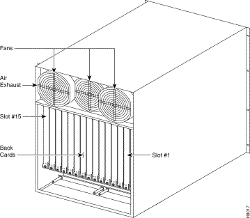
At the front of the enclosure (see Figure 2-1) are 15 slots for mounting the BPX switch front cards. Once inserted, the cards are locked in place by the air intake grille at the bottom of the enclosure.
To remove or insert cards, a mechanical latch on the air intake grille must be released by using a screwdriver and the grille must be tilted forward in order.
At the rear of the enclosure (illustrated in Figure 2-2) is another series of card slots for mounting the rear plug-in cards. These are held in place with two thumbscrews, top and bottom. A mid-plane, located between the two sets of plug-in cards, is used for interconnect and is visible only when the cards are removed.
 |
Warning To provide proper cooling, it is essential that blank faceplates be installed in all unused slots. Failure to do so will degrade node cooling and circuit card damage will result. The blank faceplates also provide RFI shielding. |


A fan assembly with three six-inch 48 VDC fans is mounted on a tray at the rear of the BPX switch shelf (see Figure 2-2). Air for cooling the cards is drawn through an air intake grille located at the bottom in the front of the enclosure. Air passes up between the vertically-mounted cards and exhausts at the top, rear of the chassis.
All unused slots in the front are filled with blank faceplates to properly channel airflow.
The primary power for a BPX switch node is -48 VDC which is bused across the backplane for use by all card slots. DC-to-DC converters on each card convert the -48V to lower voltages for use by the card.
The -48 VDC input connects directly to the DC Power Entry Module (PEM). The DC Power Entry Module (see Figure 2-3) provides a circuit breaker and line filter for the DC input.
Nodes may be equipped with either a single PEM or dual PEMs for redundancy. PEMs are mounted at the back of the node below the backplane. A conduit hookup box or an insulated cover plate is provided for terminating conduit or wire at the DC power input. It is recommended that the source of DC for the node be redundant and separately fused.

For applications requiring operation from an AC power source, an optional AC Power Supply Assembly and shelf is available. It provides a source of -48 VDC from 208/240 VAC input. A shelf, separate from the BPX switch shelf, houses one or two AC Power Supplies and mounts directly below the node cabinet. This provides a secure enclosure for the power supply assemblies (supplies cannot be removed without the use of tools).
Two of these supplies are usually operated in parallel for fail-safe redundant operation. The front of the AC Power Supplies for the BPX switch includes two green LEDs to indicate correct range of the AC input and the DC output for each individual supply (see Figure 2-4).

There are fifteen vertical slots in the front of the BPX switch enclosure to hold plug-in cards (see Figure 2-5).
The middle two slots, slots number 7 and number 8, are used for the primary and secondary Broadband Controller Cards (BCC).
The right-most slot, number 15, is used to hold the single Alarm/Status Monitor Card.
The other twelve slots, number 1 through number 6 and number 8 through number 14, can be used for the Network Interface and Service Interface cards.

There are four major groups of hardware components in the BPX switch:
Table 2-1 lists these groups and their components along with a brief description of each.
For a detailed description of these components, see:
| Card | Card Name | Where |
|---|---|---|
BPX- | Common Core Component Group |
|
BPX-BCC-32 | Broadband Controller Card, operates with versions of System Software Rel. 7.0 and above, and requires 32 Mbyte RAM for 8.1 and later software. For redundancy configuration, installed as a pair of BCC-32s. (System operation equivalent to BCC-3.) | Front |
BPX-BCC-bc | Back card (also known as LM-BCC) used only with the BCC-32. | Back |
BPX-BCC-3-64 | Broadband Controller Card, enhanced BCC-3. Note: BCC-3-64 or BCC-4 required to support VSI and MPLS. |
|
BPX-BCC-4 | Broadband Controller Card, operates with 8.4 software and above. For redundancy configuration, installed as a pair of BCC-4s. Provides 64 Mbyte of RAM and above. Supports up to 19.2 Gbps performance of BXM cards. Note: BCC-3-64 or BCC-4 required to support VSI and MPLS | Front |
BPX-BCC-3-bc | Back card (also known as LM-BCC) used with BCC-4. | Back |
BPX-ASM | Alarm/Status Monitor Card. | Front |
BPX-ASM-BC | Line Module - Alarm/Status Monitor. | Back |
| Network Interface Component Group |
| |
BPX-BXM-T3-8 BPX-BXM-E3-8 BP:X-BXM-T3-12 BPX-BXM-E3-12 | T3/E3 card with 8 or 12 ports. Card is configured for use in either network interface or service access (UNI) mode and with either a T3 or E3 interface. | Front |
BPX-T3/E3-BC | Backcard for use with a BXM-T3/E3-8 or BXM-T3/E3-12 | Back |
BPX-BXM-155-4 BPX-BXM-155-8 | BXM OC-3 cards with 4 or 8 OC-3/STM-1ports, respectively. Card is configured for use in either network interface or service access (UNI) mode. | Front |
BPX-MMF-155-4-BC BPX-SMF-155-4-BC BPX-SMFLR-155-4-BC | Backcards for BXM-155-4. | Back |
BPX-MMF-155-8-BC BPX-SMF-155-8-BC BPX-SMFLR-155-8-BC | Backcards for BXM-155-8.
| Back |
BPX-BXM-622 BPX-BXM-622-2 | OC-12 card with 1or 2 OC-12/STM-4ports. Card is configured for use in either network interface or service access (UNI) mode. | Front |
BPX-BME | Used for multicast connections. Used with SMF-622-2 backcard with port 1 looped to port 2, transmit to receive, and receive to transmit. |
|
BPX-SMF-622 BPX-SMFLR-622 BPX-XLR-622-BC | Backcards for BXM-622. The XLR card supports a 1500nm interface | Back |
BPX-SMF-622-2-BC BPX-SMFLR-622-2-BC BPX-SMFLR-622-2-BC | Backcards for BXM-622-2 and BME (BME typically would use SMF-622-2). | Back |
BPX-BME | Used for multicast connections. Used with SMF-622-2 backcard with port 1 looped to port 2, transmit to receive, and receive to transmit. | Back |
BPX-BNI-3-T3 | Broadband Network Interface Card (with 3 T3 Ports). | Front |
BPX-T3-BC | Line Module, used with BNI-T3 for 3 physical T3 ports. (Configured for 3 ports) | Back |
BPX-BNI-3-E3 | Broadband Network Interface Card (with 3 E3 Ports). | Front |
BPX-E3-BC | Line Module, used with BNI-E3 for 3 physical E3 ports. (Configured for 3 ports). | Back |
| APS Backcards and APS Redundant Backplane |
|
The APS 1+1 feature requires two BXM front cards, an APS redundant frame assembly, and two redundant type BXM backcards. The types of redundant backcard and backplane sets are:
Each of the listed model numbers includes two single backcards and one mini-backplane. | ||
The single backcards and mini-backplane can be ordered as spares. Their model numbers are: BPX-RDNT-BP= (common backplane for all redundant APS backcards) BPX-LR-155-8R-BC= (for BPX-RDNT-LR-155-8) BPX-LR-622-R-BC= (for BPX-RDNT-LR-622 BPX-SMF-155-4R-BC= (for BPX-RDNT-SM-155-4) BPX-SMF-155-8R-BC= (for BPX-RDNT-SM-155-8) BPX-SMF-622-R-BC= (for BPX-RDNT-SM-622) BPX-SMF-622-2R-BC= (for BPX-RDNT-SM-622-2 | ||
| Service Interface Component Group |
|
|
|
|
BPX-E3-BC | Line Module, used with BNI-E3 for 2 physical E3 ports. (Configured for 2 ports) | Back |
| Power Supply Group |
|
| 48 Volt DC Power Supply |
|
| Optional AC Power Supply |
|
The Cisco BPX SES PNNI Controller is an optional Service Expansion Shelf (SES) controller connected diretly to a BPX 8600 series switch to provide Private Network to Network Interface (PNNI) signaling and routing for the establishment of ATM switched virtual circuits (SVCs) and Soft Permanent Virtual Circuits (SPVCs) over a BPX 8600 wide area network. However, the SES can be used in several WAN switching applications and is not limited to function only as a BPX SES PNNI Controller
Every BPX 8600 series switch that deploys PNNI signaling and routing is collocated and attached to a BPX SES PNNI Controller. The BPX SES PNNI Controller uses Cisco's Virtual Switch Interface (VSI) protocol to control the BPX switch for its networking application.
The BPX SES PNNI Controller is a 7-slot chassis that contains two Processor Switch Modules (PXMs) that run the PNNI and SVC software. One of the PXMs serves as the active processor, while the other serves as the standby. The PNNI controller is mounted direclty atop the BPX switch and cabled to it through either the OC-3 ATM interface (Figure 1-3) or the DS3 interfaces (Figure 1-4).
For instructions on installing a Service Expansion Shelf in a BPX 8620 rack and initially powering up, see Cisco Service Expansion Shelf (SES) Hardware Installation Guide. To configure an SES PNNI for a BPX 8620, see the Cisco SES PNNI Controller Software Configuration Guide.
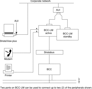
At least one node in the network (or network domain if a structured network) must include a Cisco WAN Manager network management station (see Figure 2-6).
A Y-cable may be used to connect the LAN ports on the primary and secondary BCC Line Modules, through an AUI to the LAN network, because only one BCC is active at a time.
The serial Control port may be connected to a dial-in modem for remote service support or other dial-up network management access. The serial Auxiliary Port can be used for incoming and outgoing data as well as the Autodial feature to report alarms to Cisco TAC.

![]()
![]()
![]()
![]()
![]()
![]()
![]()
![]()
Posted: Fri Jul 27 15:34:28 PDT 2001
All contents are Copyright © 1992--2001 Cisco Systems, Inc. All rights reserved.
Important Notices and Privacy Statement.