|
|

This document covers these topics:
Cisco documentation and additional literature are available in a CD-ROM package, which ships with your product. The Documentation CD-ROM, a member of the Cisco Connection Family, is updated monthly. Therefore, it might be more up to date than printed documentation. To order additional copies of the Documentation CD-ROM, contact your local sales representative or call customer service. The CD-ROM package is available as a single package or as an annual subscription. You can also access Cisco documentation on the World Wide Web at http://www.cisco.com, http://www-china.cisco.com, or http://www-europe.cisco.com.
If you are reading Cisco product documentation on the World Wide Web, you can submit comments electronically. Click Feedback in the toolbar, select Documentation, and click Enter the feedback form. After you complete the form, click Submit to send it to Cisco. We appreciate your comments.
The product number for this document: 71559
The document number for this document: DOC-7811098=
In traditional router IP networks, network managers ensure reliability by creating multiple paths through the network from every source to every destination. If a device or link on one path fails, IP traffic uses an alternate path to reach its destination.
Unlike router networks, circuit switch networks like ATM and Frame Relay transfer data by establishing circuits or virtual circuits. To ensure reliability, network managers incorporate redundant switch components: backup backplanes, power supplies, line cards, trunk cards, and so on.
But unlike router networks, switches take some time to reroute traffic when a failure occurs. Switch connection routing software, such as AutoRoute, PNNI, and MPLS, require calculating routes and reprogramming hardware for each connection. That's why router networks can reroute large aggregates of traffic more quickly than most connection-oriented networks.
Cisco's LSC redundancy recognizes that the LSC is the single point of failure for an IP+ATM network. Whether an LSC is an external router such as the Cisco 7204 router or an internal Routing Processor Module (RPM) in a BPX or MGX switch, an LSC is in the critical path for network reliability. If the LSC fails or if the LSC's port adapter goes down, the ATM-LSR also goes down and the entire connected MPLS network loses connections. As a critical component of IP+ATM networks, label switch controllers must be robust, providing continued service despite equipment or software failures, and do so quickly.
Cisco's LSC redundancy is an alternative way to increase reliability in IP networks. This reliability is nearly equivalent to that provided with the use of hot-standby routing processes. But the result is in general terms the same: if the primary controller fails, traffic can be almost instantly routed by a secondary controller. In addition, the Cisco LSC redundancy architecture reroutes traffic much faster than conventional rerouting processes.
LSC redundancy basically consists of:
In essence, two independent MPLS controllers, via VSI, control separate partitions in the IP+ATM switch, creating a set of two identical subnetworks. Multipath IP routing chooses to use both subnetworks equally, leading to identical connections in both subnetworks. If a controller in one subnetwork fails, then multipath IP routing very quickly diverts traffic to the other subnetwork.
LSC redundancy differs from hot-standby redundancy in that the LSCs do not need copies of each other's internal state or database, thus increasing reliability. LSC redundancy is simpler than hot-standby redundancy because it is not necessary to set up new connections when a controller fails. The LSC redundancy architecture requires the same amount of equipment as a network with hot-standby controllers, except that the controllers act independently, rather than in hot-standby mode.
The LSCs work independently; there is no interaction between the controllers. They do not share the controller's state or database, as other redundancy models require. Therefore, you can run different versions of the IOS software on the LSCs, which provides these advantages:
 |
Note Using different IOS software version on different LSCs is recommended only as a temporary measure. Different versions of IOS software in a network could be incompatible, although it is unlikely. For best results, run the same version of IOS software on all devices. |
In the LSC redundancy model, the LSCs do not share states or databases, which increases reliability. Sometimes, when states and databases are shared, an error in the state or database information can cause both controllers to fail simultaneously.
Also, new software features and enhancements do not affect LSC redundancy. Because the LSCs do not share states or database information, you do not have to worry about ensuring redundancy during every step of the update.
You can use different models of routers in this LSC redundancy model. For example, one LSC can be a Cisco 7200 series router, and the other LSC can be a Cisco 7500 series router. Using different hardware in the redundancy model reduces the chance that a hardware fault would interrupt network traffic.
You can implement hot or warm redundancy and switch from one model to the other. Hot redundancy can use redundant physical interfaces, slave ATM switches with Y-redundancy, and redundant LSCs. This enables parallel paths and instant failover. If your resources are limited, you can implement warm redundancy, which uses only redundant LSCs. When one controller fails, the backup controller requires some reroute time. As your network grows, you can switch from hot to warm redundancy and back, without bringing down the entire network.
Other redundancy models require complex hardware and software configurations, which are difficult to alter when you change the network configuration. You must manually change the connection routing software from hot-standby mode to warm standby mode.
You can migrate from a standalone LSC to a redundant LSC and back again without affecting network operations. Because the LSCs work independently, you can add a redundant LSC without interrupting the other LSC.
The hot LSC redundancy model provides two parallel, independent networks. Therefore, you can disable one LSC without affecting the other LSC. This feature has two main benefits:
The hot LSC redundancy model offers redundant paths for every destination. Therefore, reroute recovery is very fast. Other rerouting processes in IP+ATM networks require many steps and take more time.
In normal IP+ATM networks, the reroute process consists of the following steps:
After this reroute process, the new path is ready to transfer data. However, rerouting data by using this process takes time.
The hot LSC redundancy method allows you to quickly reroute data in IP+ATM networks without using the normal reroute process. Hot LSC redundancy creates active parallel paths. Every destination has at least one alternative path. If a device or link along the path fails, the data uses the other path to reach its destination. The hot LSC redundancy model provides the fastest reroute recovery time for IP+ATM networks.
The architecture is distinguished by two main features:
Consider a basic IP network of switches with one MPLS controller (or a hot-standby pair of them) and MPLS Edge Label Switch Routers (LSR) feeding the edge of the network.
The LSC redundancy architecture adds to this basic network two independent controllers of the same type (such as MPLS), enabled by the Virtual Switch Interface (VSI) to control two separate partitions on the same IP+ATM switch. The pair of controllers on the switch form two separate MPLS control planes for the network that effectively create two independent parallel IP subnetworks.
Provided that the two independent MPLS controllers on each switch have identical shares of the switch's resources and link capacity, the two subnetworks are identical. The two identical, parallel IP subnetworks exist on virtually the same equipment that would otherwise support only one IP network.
 |
Note Each control plane and partition might have a redundant pair of controllers, but these are coupled. Note that the two independent controllers must be of the same type. Also, the equipment must have sufficient connection capacity for the doubled-up connections. |
The LSC redundancy solution differs from hot-standby redundancy in that the MPLS controllers need not have copies of each other's internal state.
The second feature of the LSC redundancy architecture is the linkage of the two parallel subnetworks on the same physical ATM-LSR at the edge.
This LSC redundancy network might use the Open Shortest Path First (OSPF) protocol with equal-cost multipath or a similar IP routing protocol with multipath capability. Because there are two identical, parallel IP subnetworks, there are at least two equally good paths from every edge LSR to every other edge LSR, one in each subnetwork.
OSPF equal-cost multipath chooses to distribute traffic evenly across both sets of paths (and hence both subnetworks). Because of this, MPLS sets up two identical sets of connections for the two MPLS control planes. IP traffic is shared evenly across the two sets of connections, across both control planes.
LSC Redundancy works with any routing protocol. For example, you can use:
If there were a failure in one MPLS controller in one switch, some paths in one of the subnetworks would no longer work. If there were only one subnetwork, there would be an undesirable interruption in passing data while other switches break connections and reroute them around the failed node.
However, because all connections are mirrored in the secondary subnetwork, there are already alternative paths for the traffic without the need to establish new links. All that is required is for multipath routing to detect the failure of one set of paths and to divert the traffic onto the remaining good paths. Because connections on the other paths have already been set up, the interruption to traffic flow is much smaller than if new connections were required.
The LSC redundancy architecture supports these operational modes:
You can configure the LSC controller to provide two levels of redundancy, providing either equal cost routing (Hot Redundancy) or unequal-cost routing (Warm Redundancy).
In both cases, the two LSCs:
Hot and warm redundancy differ in the following ways:
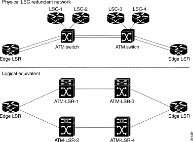
The hot redundancy level (Figure 1) provides the fastest rerouting.
The backup MPLS controller provisions connections in tandem with the primary controller. Both controllers are active or "hot" at all times, giving each destination two independent paths, each path generated by one of the two controllers.
The two partitions on the switch must be configured with equal bandwidth and cross-connect space. Also, both LSCs must run the same routing protocols.
The result is that the edge LSRs have multiple routes to the same destination and request multiple labels. If one controller fails, only one of the two paths fails; the secondary controller already has the labels established and immediately provides an active backup path to handle the traffic with no time lost for rerouting or setting up labels.
 |
Note By placing two LSCs on an ATM switch, they become two logically separate ATM-LSRs, which is what the "Logical equivalent" is showing. It's important to clearly distinguish between an LSC and an ATM-LSR: an LSC is not an ATM-LSR, it is merely part of one. |
Warm redundancy (Figure 2) is more flexible but less robust than hot redundancy.
Both LSCs are active on the switch, but to avoid overburdening the single VC, one controller is designated "primary" with least-cost path and the other is designated "backup" with higher cost. The edge LSRs have only one route over the primary (least-cost) LSC.
The backup controller, configured with higher routing cost, creates only one physical path for each destination. If the primary controller fails, the backup controller creates new paths for the destinations.
The advantage of warm redundancy is that the switch's resources are conserved because only one partition is in use at a given time. Unlike hot redundancy, the two partitions on the switch need not be configured for equal bandwidth and cross-connect space. Also, the two controllers can run different routing protocols. Thus, warm redundancy offers additional flexibility
The disadvantage of warm redundancy is that there is no way for the backup processor to maintain existing connections during the changeover. For the backup controller to reestablish the path takes at least one reroute time to become active. This also incurs LDP negotiation/bind time.
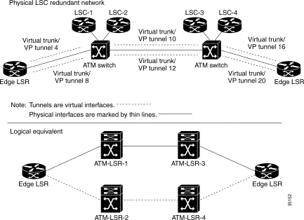
The LSC and slave ATM switch have these characteristics:
If a component on the LSC fails, the ATM switch's IP switching function is disabled. The stand-alone LSC is the single point of failure.
The VSI implementation includes these characteristics:
To make an LSC redundant, you perform these basic steps:
In the LSC redundancy model, two LSCs control different partitions of the ATM switch. When you partition the ATM switch for LSC redundancy, follow these guidelines:
See the Cisco BPX 8600 Series documentation for more information about configuring the slave ATM switch.
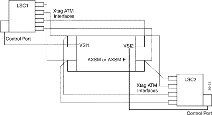
The parallel VSI model means that the physical interfaces on the ATM switch are shared by more than one LSC. For example:
With this mapping, you achieve fully meshed independent masters.
Figure 3 shows four ATM physical interfaces mapped as four XtagATM interfaces at LSC1 and LSC2. Each LSC is unaware that the other LSC is mapped to the same interfaces. Both LSCs are active all the time. The ATM switch runs the same VSI protocol on both partitions.
To ensure reliability throughout the LSC redundant network, you can also implement:
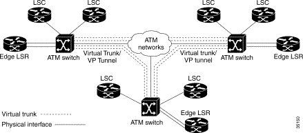
In hot redundancy, the LSCs run parallel and independent Label Distribution Protocols (LDPs). At the edge LSRs, when the LDP has multiple routes for the same destination, it requests multiple labels. It also requests multiple labels when it needs to support Class of Service (CoS). When one LSC fails, the labels distributed by that LSC are removed.
To achieve hot redundancy, you can implement these redundant components:
Virtually any configuration of switches and LSCs that provides hot redundancy can also provide warm redundancy. You can also switch from warm to hot redundancy with little or no change to the links, switch configurations, or partitions.
If you run the same routing protocols, you specify a higher cost for the interfaces on the backup LSC. This causes the data to use only the lower-cost path. This also saves resources on the ATM switch, because the edge LSR requests LVCs only through the lower-cost LSC. When the primary LSC fails, the edge LSR uses the backup LSC and creates new paths to the destination. Creating new paths requires reroute time and LDP negotiation time.
Normally, LSCs include edge LSRs. In the "dedicated" LSC mode, the LSC removes edge LSR functionality. In Cisco 6400 NRP-based LSCs, the dedicated LSC mode of operation provides an opportunity for the LSC to be scaled. To achieve the edge LSR functionality, the LSC creates a label switch path (LSP) for each destination in the route table.
With LSC redundancy, if 400 destinations exist in the network, each redundant LSC adds 400 head-end VCs. In hot redundancy mode, 800 head-end VCs are created for the LSCs. If the LSCs are not edge LSRs, then 800 LVCs are wasted.
The number of LVCs increases as the number of redundant LSCs increases. In the case of a VC-merged system, the number of LVCs can be low. However, in non-VC-merged system, using the dedicated LSC mode is recommended.
The sample configuration settings shown in this section assumes a network topology with two BPX switches (BPX1 and BPX2). Each BPX is connected to its own edge label switch router (LER) and each BPX supports two LSCs in separate partitions.
The diagram in Figure 5 indicates the connections to support two active independent controllers on each BPX switch with two independent paths for each destination; that is, hot redundancy.
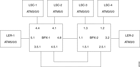
LSC1 4.4
LSC2 4.1
LER1 5.1
LSC3 1.3
LSC4 1.2
LER2 3.2
Use the cnfrsrc command to configure all VSI and AutoRoute resources. The following dsprsrc command screens show the recommended settings the BPX1 side of the basic topology. Naturally, depending on your network, your will need to adjust the resource parameters to maximize efficiency.
Note that the configuration for BPX2 and its LER2, LSC3 and LSC4 are almost identical to those of the BPX1 but with different addresses for the BPX, the router ATM port, and loopback.
-----------------------------------------------------------------------
Port/Trunk : 4.4

Maximum PVC LCNS:             256     Maximum PVC Bandwidth:148207
                                      (Statistical Reserve: 5000)

Partition 1

Partition State :             Enabled
Minimum VSI LCNS:             0
Maximum VSI LCNS:             4096
Start VSI VPI:                100
End VSI VPI :                 200
Minimum VSI Bandwidth :       0       Maximum VSI Bandwidth :        200000
VSI ILMI Config       :       0

Last Command: dsprsrc 4.4 1

-----------------------------------------------------------------------
Port/Trunk : 4.4

Maximum PVC LCNS:             256     Maximum PVC Bandwidth:148207
                                      (Statistical Reserve: 5000)

Partition 2

Partition State :             Disable


Last Command: dsprsrc 4.4 2

-----------------------------------------------------------------------
Port/Trunk : 4.1

Maximum PVC LCNS:             256     Maximum PVC Bandwidth:148207
                                      (Statistical Reserve: 5000)

Partition 1

Partition State :             Disable


Last Command: dsprsrc 4.1 1

-----------------------------------------------------------------------
Port/Trunk : 4.1

Maximum PVC LCNS:             256     Maximum PVC Bandwidth:148207
                                      (Statistical Reserve: 5000)

Partition 2

Partition State :             Enabled
Minimum VSI LCNS:             0
Maximum VSI LCNS:             4096
Start VSI VPI:                201
End VSI VPI :                 300
Minimum VSI Bandwidth :       0       Maximum VSI Bandwidth :        200000
VSI ILMI Config       :       0

-----------------------------------------------------------------------
Port/Trunk : 4.8

Maximum PVC LCNS:             256     Maximum PVC Bandwidth:148207
                                      (Statistical Reserve: 5000)

Partition 1

Partition State :             Enabled
Minimum VSI LCNS:             0
Maximum VSI LCNS:             4096
Start VSI VPI:                100
End VSI VPI :                 200
Minimum VSI Bandwidth :       0       Maximum VSI Bandwidth :        200000
VSI ILMI Config       :       0

Last Command: dsprsrc 4.8 1

-----------------------------------------------------------------------
Port/Trunk : 4.8

Maximum PVC LCNS:             256     Maximum PVC Bandwidth:148207
                                      (Statistical Reserve: 5000)

Partition 2

Partition State :             Enabled
Minimum VSI LCNS:             0
Maximum VSI LCNS:             4096
Start VSI VPI:                201
End VSI VPI :                 255
Minimum VSI Bandwidth :       0       Maximum VSI Bandwidth :        100000
VSI ILMI Config       :       0

Last Command: dsprsrc 4.8 2

-----------------------------------------------------------------------
Virtual Trunk : 4.5.1

Maximum PVC LCNS:             256     Maximum PVC Bandwidth:867
                                      (Statistical Reserve: 1000)

Partition 1

Partition State :             Enabled
Minimum VSI LCNS:             0
Maximum VSI LCNS:             4096
Start VSI VPI:                35
End VSI VPI :                 35
Minimum VSI Bandwidth :       0       Maximum VSI Bandwidth :        1000
VSI ILMI Config       :       0

Last Command: dsprsrc 4.5.1 1


-----------------------------------------------------------------------
Virtual Trunk : 3.5.1

Maximum PVC LCNS:             256     Maximum PVC Bandwidth:867
                                      (Statistical Reserve: 1000)

Partition 1

Partition State :             Enabled
Minimum VSI LCNS:             0
Maximum VSI LCNS:             4096
Start VSI VPI:                36
End VSI VPI :                 36
Minimum VSI Bandwidth :       0       Maximum VSI Bandwidth :        1000
VSI ILMI Config       :       0

Last Command: dsprsrc 3.5.1 1

-----------------------------------------------------------------------
Port/Trunk : 5.1

Maximum PVC LCNS:             256     Maximum PVC Bandwidth:30000

Partition 1

Partition State :             Enabled
Minimum VSI LCNS:             0
Maximum VSI LCNS:             4096
Start VSI VPI:                100
End VSI VPI :                 200
Minimum VSI Bandwidth :       0       Maximum VSI Bandwidth :        30000
VSI ILMI Config       :       0


Last Command: dsprsrc 5.1 1

-----------------------------------------------------------------------
Port/Trunk : 5.1

Maximum PVC LCNS:             256     Maximum PVC Bandwidth:30000

Partition 2

Partition State :             Enabled
Minimum VSI LCNS:             0
Maximum VSI LCNS:             4096
Start VSI VPI:                201
End VSI VPI :                 255
Minimum VSI Bandwidth :       0       Maximum VSI Bandwidth :        30000
VSI ILMI Config       :       0


Last Command: dsprsrc 5.1 2
!
version 12.1
service timestamps debug uptime
service timestamps log uptime
no service password-encryption
!
hostname 7500-12
!
boot system slot0:rsp-pv-mz.121-1.1.T
enable secret 5 $1$QvGU$NDhlWJM9eYcXN3gJfgZcc1
enable password cisco
ip subnet-zero
ip cef
!
no ip domain-lookup
clns routing
tag-switching tdp router-id Loopback0
!
interface Loopback0
 ip address 12.12.12.12 255.255.255.255
!
nterface ATM5/0/0
 no ip address
 no ip route-cache distributed
 atm framing cbitplcp
 no atm ilmi-keepalive
 tag-switching ip
!
interface ATM5/0/0.1 tag-switching
 ip unnumbered Loopback0
 tag-switching atm multi-vc
 tag-switching atm vpi 100-200
 tag-switching ip
!
interface ATM5/0/0.2 tag-switching
 ip unnumbered Loopback0
 tag-switching atm multi-vc
 tag-switching atm control-vc 201 40
 tag-switching atm vpi 201-255
 tag-switching ip
!
router ospf 50
 network 12.12.12.12 0.0.0.0 area 5
!
ip classless
ip route 0.0.0.0 0.0.0.0 172.29.113.1
no ip http server
!
!
tftp-server slot0:rsp-jsv-mz.120-6.5.T4
!
line con 0
 exec-timeout 0 0
 transport input none
line aux 0
line vty 0 4
 exec-timeout 0 0
 password cisco
 login
!
no scheduler max-task-time
end
!
version 12.1
no service pad
service timestamps debug uptime
service timestamps log uptime
no service password-encryption
service compress-config
!
hostname R7200-12
!
boot system slot0:c7200-p-mz.121-1.1.T
enable password cisco
!
!
!
!
!
ip subnet-zero
ip cef
no ip domain-lookup
!
tag-switching tdp router-id Loopback0
!
!
interface Loopback0
 ip address 112.112.112.112 255.255.255.255
 no ip route-cache
 no ip mroute-cache
!
interface ATM3/0
 no ip address
 no ip mroute-cache
 tag-control-protocol vsi
 no atm ilmi-keepalive
!
!
interface XTagATM48
 ip unnumbered Loopback0
 no ip route-cache cef
 extended-port ATM3/0 bpx 4.8
 tag-switching ip
!
interface XTagATM51
 ip unnumbered Loopback0
 no ip route-cache cef
 extended-port ATM3/0 bpx 5.1
 tag-switching ip
!
interface XTagATM351
 ip unnumbered Loopback0
 no ip route-cache cef
 extended-port ATM3/0 bpx 3.5.1
 tag-switching ip
!
interface XTagATM451
 ip unnumbered Loopback0
 no ip route-cache cef
 extended-port ATM3/0 bpx 4.5.1
 tag-switching ip
!
router ospf 50
 network 112.112.112.112 0.0.0.0 area 5
!
ip classless
ip route 0.0.0.0 0.0.0.0 172.29.113.1
no ip http server
!
!
line con 0
 exec-timeout 0 0
 password cisco
 transport input none
line aux 0
line vty 0 4
 exec-timeout 0 0
 password cisco
 login
!
end
!
version 12.1
no service pad
service timestamps debug uptime
service timestamps log uptime
no service password-encryption
!
hostname R7200-13
!
boot system tftp c7200-p-mz.121-1.1.T 172.29.113.87
enable password cisco
!
!
!
!
!
ip subnet-zero
ip cef
no ip domain-lookup
!
tag-switching tdp router-id Loopback0
!
!
!
!
!
interface Loopback0
 ip address 13.13.13.13 255.255.255.255
interface ATM5/0
 no ip address
 tag-control-protocol vsi id 2
 no atm ilmi-keepalive
 tag-switching ip
!
interface Hssi6/0
 no ip address
 no ip mroute-cache
 shutdown
 fair-queue
!
interface XTagATM48
 ip unnumbered Loopback0
 no ip route-cache cef
 extended-port ATM5/0 bpx 4.8
 tag-switching atm control-vc 201 40
 tag-switching ip
!
interface XTagATM51
 ip unnumbered Loopback0
 extended-port ATM5/0 bpx 5.1
 tag-switching atm control-vc 201 40
 tag-switching ip
!
interface XTagATM351
 ip unnumbered Loopback0
 no ip route-cache cef
 extended-port ATM5/0 bpx 3.5.1
 tag-switching atm control-vc 36 40
 tag-switching ip
!
interface XTagATM451
 ip unnumbered Loopback0
 no ip route-cache cef
 extended-port ATM5/0 bpx 4.5.1
 tag-switching atm control-vc 35 40
 tag-switching ip
!
router ospf 50
 network 13.13.13.13 0.0.0.0 area 5
!
ip classless
ip route 0.0.0.0 0.0.0.0 172.29.113.1
no ip http server
!
!
!
line con 0
 exec-timeout 0 0
 transport input none
line aux 0
line vty 0 4
 exec-timeout 0 0
 no login
!
no scheduler max-task-time
end
![]()
![]()
![]()
![]()
![]()
![]()
![]()
![]()
Posted: Fri May 4 08:27:31 PDT 2001
All contents are Copyright © 1992--2001 Cisco Systems, Inc. All rights reserved.
Important Notices and Privacy Statement.