|
|

Table Of Contents
Optimizing Traffic Routing and Bandwidth
Specifying Channel Utilization
Optimizing Traffic Routing and Bandwidth
To achieve peak network performance, the routing of traffic and the use of available bandwidth is configurable. The information used in configuring traffic routing and bandwidth is gathered from historical network trends. The tasks required to optimize the network are specifying channel utilization, specifying the class of service (including the use of the priority bumping feature), and managing bandwidth. These tasks are discussed in the paragraphs that follow.
Specifying Channel Utilization
Use the cnfchutl command to specify the expected utilization of Frame Relay, data, or voice channel as a percentage of the channel's total capacity. The specified value can be in the range of 0% to 100%; 100% is the default for data and Frame Relay channels. The default for voice channels is 40%. To display the utilization of a particular trunk, use the dsptrkutl command. This command displays a details on the packets transmitted over the trunk. The user can specify the rate in seconds at which the screen is updated. Use the dspload command to display the load for a specified trunk at a node.
Specifying Class of Service
Use the cnfcos command to specify a class of service (COS) for a Frame Relay, data, or voice channel connection. The class of service is the delay in seconds before the network reroutes a connection in the event of a trunk failure. The range is 0-15. By spreading out the COS numbers to vary the rerouting delay, one class of channels has a chance to reroute before the another class starts to reroute.
Specifying Priority Bumping
Priority bumping allows both BPX and IGX to switch connections that are classified as more important (via COS value) to bump existing connections that are less important when network resources become scarce. While the existing AutoRoute feature is capable of automatically redirecting all failed connections onto other paths, use the priority bumping command cnfbmpparm command to activate the priority bumping feature in order to retain important connections when network resources are diminished to a point when all connections cannot be sustained. Network resources are reclaimed for the more important connections by bumping (or derouting) the less important connections. Priority bumping is triggered by insufficient resources (such as bandwidth), resulting from a number of events, including changes to the network via the addcon, upcon, cnfcon, cnfpref, cnftrk, deltrk, as well as a trunk line/card failure, and node failure. The most typical event is a trunk failure.
In priority bumping, connections are defined by their Class of Service (COS) value. Connections tagged with the lowest COS, zero, are the most important to maintain. Connections tagged with the highest COS, 15, have the lowest priority. Connections that have a COS value in between 0 and 15 are progressively less important as they ascend upward.
The COS values are categorized into a set of 8 bands. These bands can be configured to meet the specific needs of each network. However, when priority bumping is enabled, the default settings are as follows:
Note
Configuring priority bumping requires a thorough knowledge of AutoRouting capabilities (also known as Automatic Routing Management) available bandwidth, and COS values.
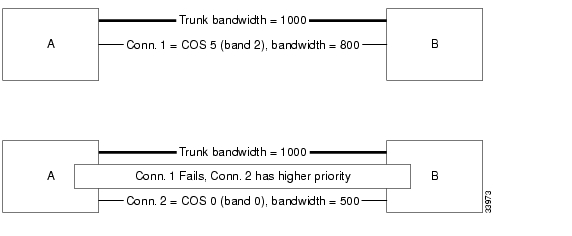
For an example of how this feature works, refer to Figure 10-1. If a trunk is established between switches A and B with a bandwidth of 1000 load units, it can support connection 1 (Conn. 1) with a bandwidth of 800. However, if we add a second connection (Conn. 2) with a bandwidth of 500, the trunk can no longer support both connections.
Conn. 1 (800) + Conn. 2 (500) = total bandwidth of 1300
When priority bumping is enabled the least important connection is bumped.
Conn. 1 has COS of 5
Conn. 2 has a COS of 0
The lower COS connection has the higher priority. Conn. 1 with a COS of 5 is failed in order for Conn. 2 traffic (with a COS of 0) to flow without interruption.
Figure 10-1 Priority Bumping between Two Switches
Another example with three switches is illustrated in Figure 10-2. Three trunks are established:
Two connections are established:
All traffic on the connections is uninterrupted, but if Trunk AB fails, Trunk BC, with a bandwidth of 600, cannot handle the total bandwidth of both connections (700). Conn. 1 is in Band 5; Conn. 2 is in Band 7. The lower the band, the higher the priority. Conn. 2 is bumped to accommodate Conn. 1 with the higher priority.
Note
Figure 10-2 Priority Bumping between Three Switches
Managing Bandwidth
There are a number of commands that assist in managing bandwidth to achieve satisfactory traffic patterns.
Summary of Commands
Table 10-1 Shows the full command name and starting page for each description.
cnfbmpparm
Priority bumping requires a number of configuration parameters which are saved in the BRAM and sent to the Standby Processor card. The parameters consist of a feature activation flag, a bundle size, and a set of seven COS bands (0-7), implicitly defining eight COS bands. Unlike AutoRoute capabilities, which include a number of different operational flavors, priority bumping is strictly a COS-based (or, more accurately, band-based) algorithm. Each band is defined by the low-end COS value within the band. Band 0 (implicitly defined) is the most important one, whereas Band 7 is the least important. Each connection within a band is equally important, despite the fact that it might be tagged with a different COS. Note that Band 0 is not bumpable.
A minimum of two bands are required to be defined for the priority bumping feature to work. A network with only one band is equivalent to having the priority bumping feature disabled.
The entire network must be upgraded to 9.3.0 in order for the priority bumping feature to be operational.
Use the following steps to setup priority bumping:
1.
Example 10-1 Purchase priority bumping on a BPX using the cnfswfunc command, option 6
Purchasing PB license on a BPX---------------------------------------------bpx1 TN StrataCom BPX 8620 9.3.0K Jan. 26 2000 14:16 PSTIndex Status Function1 Enabled Configuration Save/Restore2 Enabled ForeSight3 Enabled Multiple VTs (6 sessions enabled)4 Enabled Virtual Trunks5 Enabled ABR standard with VSVD6 Enabled Priority BumpingLast Command: cnfswfunc 6 e2.
The default configuration when priority bumping is enabled is shown below.
3.
a.
b.
c.
You then can use the dspcons command to view connection routing.
4.
Example 10-2 COS-based loads
igxaf1 TN StrataCom IGX 8420 9.3 the.0F Jan. 10 2000 15:33 PSTConfigured Trunk Loading: TRK igxaf1 16.4--10.1 bpx2Band: CoS Xmt-c Rcv-cB1 : 1- 1 191 191 Conid In Use+Avail 256B2 : 2- 2 288 288B3 : 3- 3 1036 1036 VPC conids: 0/256B4 : 4- 4 216 216B5 : 5- 5 216 216 Trunk type is TerrestrialB6 : 6-13 900 900 Trunk supports cell routingB7 :14-15 300 300 Trunk does not use ZCSTotal In Use 3147 3147 Trunk end supports all gateway typesReserved 400 400 Gateway conns: 28/200Available 75 75 Traffic: V TS NTS FR FST CBR NRT-VBR ABRTotal Capacity 3622 3622 RT-VBRLcn/GwLcn bmap, oe: 7F/5F,7F/00Limitations
1.
2.
3.
4.
5.
Full Name
Configure priority bumping.
Syntax
cnfbmpparm [1 [<enable>|<disable>] ]
[2 <bundle> ]
[3 <b1> <b2> [<b3> [<b4> [<b5> [<b6> [<b7>]]]]]]
Attributes
1-2
No
No
IGX or BPX
NPM-32
NPM-64
BCC-64.
Yes
Related Commands
dspbmpparm, dspbmpstats
Example 10-3 Default Setup, Eight COS Bands
The default configuration is priority bumping disabled. However, when the feature is simply enabled (without changing the other banding parameters), the network would operate with eight COS bands.
Example 10-4 Refined Granularity of COS Banding
A sample PB_Band configuration of 1, 2, 3, 4, 5, 11 and 13 provides a better granularity of COS banding at the more important end of the spectrum
Another sample PB_Band configuration of 3, 5, 8, 12, 13, 14 and 15 provides a better granularity of COS banding at the less important end of the spectrum.
Example 10-5 Reduced COS Banding, Better Operational Performance
A sample PB_Band configuration of 1, 2, 8, 9, 9, 9 and 9 provides a reduced COS banding, thus allowing better routing performance (with fewer iterations through the bands)
The following screen illustrates how the bands in Example 10-5 are configured, than displayed.
bpx1 TN StrataCom BPX 8620 9.3.0K Jan. 26 2000 14:28 PST1 Priority Bumping Enabled [ YES]2 Priority Bumping Bundle [ 10] (D)3 Priority Bumping Bands:Bumping Band 1 [ 1] (D)Bumping Band 2 [ 2] (D)Bumping Band 3 [ 8] (D)Bumping Band 4 [ 9] (D)Bumping Band 5 [ 9] (D)Bumping Band 6 [ 9] (D)Bumping Band 7 [ 9] (D)Last Command: cnfbmpparm 3 1 2 8 9 9bpx1 TN StrataCom BPX 8620 9.3.0K Jan. 26 2000 14:28 PST1 Priority Bumping Enabled [ YES]2 Priority Bumping Bundle [ 10] (D)3 Priority Bumping Bands:Bumping Band 1 [ 1] (D)Bumping Band 2 [ 2] (D)Bumping Band 3 [ 8] (D)Bumping Band 4 [ 9] (D)Bumping Band 5 [ 9] (D)Bumping Band 6 [ 9] (D)Bumping Band 7 [ 9] (D)Priority Bumping Active on this node [ YES]Number of Priority Bumping Bands [ 4] (D)Last Command: dspbmpparmExample 10-6 Minimum COS Banding
Another sample PB_Band configuration of 1, 1, 1, 1, 1, 1 and 1 provides a minimum COS banding of only two bands)
cnfchutl
Informs the system software of the expected utilization rate of connections with traffic-dependent compression algorithms (voice connections with VAD, data connections with DFM, Frame Relay connections). The software load model then takes the user-specified rate of the connection and modifies it by using the percent of utilization you specify with cnfchutl. The resulting rate is used in calculations for loading trunks. The load model uses these figures instead of calculated estimates from real traffic patterns.
For the full benefits of the compression algorithms to be used, the default utilizations should be modified after traffic studies have been performed. Traffic studies of Frame Relay connections should be used to determine optimum utilization settings. When calculating loads in a network, the load allocated to a connection is:
channel utilization x full load for the connection type
For example, with a channel utilization of 50% and a full load of 480 packets per second, the load allocated to a connection is:
0.50 x 480 pps = 240 pps
For voice connections with VAD turned off, the bandwidth allocated is always the maximum bandwidth for the connection type. In other words, the utilization, although configurable, is ignored for a voice channel without VAD and a data channel without DFM.
If you use cnfchutl to increase the utilization of a connection, the system verifies that the additional bandwidth is available on the connection's current route. If the bandwidth is not available, the system attempts to reroute the connection. If no other route is found, the connection is failed.
If you use cnfchutl to decrease the utilization of a connection, the system makes the bandwidth available to other connections that require a route. The screen displayed by the cnfchutl command depends upon whether a data channel, voice channel, or Frame Relay channel is specified.
Full Name
Configure channel utilization
Syntax
cnfchutl <channel(s)> <%_util>
Related Commands
dspchcnf
Attributes
Example 1
cnfchutl 5.1 40
Description
Set utilization on data channel 5.1 at 40%.
System Response
alpha TRM YourID:1 IGX 8420 9.2 Aug. 23 1998 10:45 PSTMaximum EIA % DFM Pattern DFMChannels Update Rate Util Length Status5.1 15 40 8 Enabled5.2-4 2 100 8 EnabledLast Command: cnfchutl 5.1 40Next Command:Example 2
cnfchutl 14.1 55
Description
Set utilization on voice channel 14.1 at 55%.
System Response
alpha TRM YourID:1 IGX 8420 9.2 Aug. 16 1998 10:10 PST% Adaptive Gain (dB) Dial OnHk CondChannels Util Voice In Out Type Interface Type A B C D Crit.14.1 55 Enabled -4 - User Unconfig ? ? - - a14.2-24 40 Enabled 0 - Inband Unconfig ? ? - - aLast Command: cnfchutl 14.1 55Next Command:Example 3
cnfchutl 8.1.100 60
Description
Set utilization on Frame Relay channel 8.1.100 at 60%.
System Response
alpha TRM YourID:1 IGX 8420 9.2 Aug. 23 1998 10:45 PSTFrame Relay Channel Configuration Port: 8.1From Minimum Peak AvgFrame Cmax VC Q ECN Q % Util 8.1.100 9.6 * 70 10 65535 65535 60 8.1.301 9.6 * 70 10 65535 65535 100Last Command: cnfchutl 8.1.100 60Next Command:
cnfcmb
Configures a time the node waits for a second packet to become available for placing in an ATM cell. You can use the cnfcmb command to control the time that the node waits for individual traffic types. When you enter a value for a parameter, switch software multiplies the value by 125 microseconds to derive the timeout.
Full Name
Configure combine timeout parameters
Syntax
cnfcmb <parameter number> <value>
Related Commands
dspchcnf
Attributes
Example 1
cnfcmb 1 1
Description
Change the timeout for voice packets from the default of 2 * 125 microseconds to 1 * 125 microseconds.
System Response
pubsigx1 TN SuperUser IGX 32 9.2 Sep. 17 1998 23:38 PDTSystem-Wide Combine Timeout Parameters1 Packet Combining Timeout for Voice (125 usec *)...................... 22 Packet Combining Timeout for Time Stamped Traffic (125 usec *)....... 23 Packet Combining Timeout for High Priority Traffic (125 usec *)...... 04 Packet Combining Timeout for Non Time Stamped Traffic (125 usec *)... 25 Packet Combining Timeout for Bursty Data 1 Traffic (125 usec *)...... 2556 Packet Combining Timeout for Bursty Data 2 Traffic (125 usec *)...... 255This Command: cnfcmbWhich parameter do you wish to change: 1 1
cnfcos
Determines the priority for rerouting a connection. You determine the priority by specifying a delay before the network reroutes one or more failed connections. The COS applies to:
•
•
•
When connections have failed (typically due to a trunk failure), the network reroutes them according to priorities that are set primarily by the class of service (COS). The value of COS is the number of seconds the network waits before it begins to reroute the connection, so the COS determines the rerouting order for connections owned by a node. The range of possible COS values is 0-15.
The number of connections in a network has an effect on the increment between COS values you should use. For larger numbers of connections, you should allow more time to reroute the connections in a class. To facilitate the greater time required to reroute larger numbers of connections, use a larger increment between COS values. In a larger network, for example, you could specify COS values that are 3 seconds apart (such as 0, 3, 6, 9, 12, and so on, for example). For a network with less traffic, assign COS values in increments of 1 or 2. This strategy ensures that all connections of a given COS reroute before the connections with the next COS start to reroute.
Full Name
Configure class of service for connections
Syntax
cnfcos <group | channel(s)> <cos>
Related Commands
dspcons
Attributes
Example 1
cnfcos 5.1 0
Description
Set the COS for channel 5.1 to 0.
System Response
alpha TRM YourID:1 IGX 8420 9.2 Aug. 16 1998 10:12 PSTLocal Remote Remote RouteChannel NodeName Channel State Type Compression Code Avoid COS O5.1 beta 25.1 Ok 256 7/8 0 L9.1.100 gamma 8.1.200 Ok fr 0 L9.2.400 beta 19.2.302 Ok fr 0 L14.1 gamma 15.1 Ok v 0 LLast Command: cnfcos 5.1 0Next Command:
cnfpref
Specifies the preferred route for a connection or range of connections. Enter cnfpref only at a node that is an end point of the connection. This command applies only to connections that exist within a domain. Do not attempt to execute cnfpref on connections that exist between domains.
The preferred route for a connection is used when possible. If the preferred route is different from the existing route, the connection automatically moves to the preferred route whenever network conditions allow (for example, when trunks are out of alarm and sufficient bandwidth exists).
Full Name
Configure preferred route for connections
Syntax
cnfpref <channel(s) | *> <route> < + | -> [d]
Related Commands
dsprts
Attributes
Example 1
cnfpref 14.1 13/beta 15/gamma d
Description
Select the preferred route for channel 14.1 to be through beta trunk 13 to beta then to gamma trunk 15. For gamma, the "d" in the command specifies that the route is directed.
System Response
alpha TRM YourID:1 IGX 8420 9.2 Aug. 16 1998 10:22 PSTFrom 14.1 Route14.1alpha 14--13beta 15--15gammaPref:(D) alpha 14--13beta 15--15gammaLast Command: cnfpref 14.1 13/beta 15/gamma dNext Command:Example 2
cnfpref 6.4 -
Description
Remove the preferred route for channel 6.4.
Example 3
cnfpref * +
Description
Designate the current routing of all locally owned connections to be the preferred routing. Using a "-" instead of a "+" in the command would remove the preferred routing designation of all locally owned connections.
System Response
alpha TRM YourID:1 IGX 8420 9.2 Aug. 23 1998 10:48 PSTChan/Grp Route5.1alpha 10-- 7betaPref: alpha 10-- 7beta9.1.100alpha 14--13beta 15--15gammaPref: alpha 14--13beta 15--15gamma9.1.200alpha 10-- 7beta 15--15gammaPref: alpha 10-- 7beta 15--15gamma9.2.400alpha 10-- 7betaPref: alpha 10-- 7betaLast Command: cnfpref * +Next Command:
Table 10-7 cnfpref-Optional Parameters
d
Specifies directed routing. If the preferred route is not available, the connection is failed.
cnfrtcost
Configures the cost cap for a connection when cost-based routing is configured.
A maximum allowable cost value (cost cap) is used during route determination to prevent selection of a route which exceeds an acceptable cost. For routing based on delay, the cost cap is the acceptable end-to-end delay for the connection type. This cap is configured network-wide per delay-sensitive connection type.
For routing based on trunk cost, the cost cap is the acceptable end-to-end cost. This cap is configured per connection. The default cost cap is 100, which is derived from the maximum hops per route (10) and default cost per trunk (10). The cost cap can be changed at any time. If the cost cap is decreased below the current route cost, the connection is not automatically rerouted. A manual reroute is required to route the connection to fit under the new cost cap. This gives the user more control over the connection reroute outage.
Note
Full Name
Display connection loading
Syntax
cnfrtcost <connection> <max cost>
<connection> indicates the connection endpoint (that is, slot.port.vpi.vci)
<max cost> indicates the maximum allowable route cost
Valid values = 1 - 500
Related Commands
dspcon, cnfpref, dsprtcache
Attributes
Example
cnfrtcost 9.2.5.100 40 1
After configuring the cost cap for a connection, you can check to see the configured value with the dspcon command, as is shown in the System Response example. This is the dspcon response for 9.2.5.100 with the additional fields of Max Cost (40) and Route Cost (1). For a route optimized on trunk delay, the cost labels are updated to indicate delay: Max Cost becomes Max Delay and Route Cost becomes Route Delay.
Description
Select route cost for channel 9.2.5.100.
System Response
sw203 TN StrataCom BPX 8620 9.1.a4 Sep. 24 1998 18:18 GMTConn: 9.2.5.100 sw242 14.2.5.100 cbr Status:OKPCR(0+1) % util CDVT(0+1) Policing50/50 100/100 10000/10000 4/4Owner: LOCAL Restriction: NONE COS: 0TestRTD: 0 msec Trunk Cell Routing Restrict: Y Max Cost: 40 Route Cost: 1Path: sw203 3.1.1-- 2.1.1sw242Pref: Not Configuredsw203 ASI-T3 : OK sw242 ASI-OC-3 : OKLine 9.2 : OK Line 14.2 : OKOAM Cell RX: Clear NNI : OKNNI : OKLast Command: dspcon 9.2.5.100Next Command:dncon
Deactivates (downs) a connection, bundle of connections, a connection group or all connection in a COS or COS range. The dncon command temporarily removes one or more connections from the network. This command is useful for temporarily removing voice connections when additional bandwidth is necessary for other types of connections.
Connections can be downed immediately or with courtesy. Even with immediate downing, a prompt appears that requests confirmation. With courtesy downing, the system waits until the connection is onhook before downing the connection. Courtesy downing is possible only if the onhook status has been configured with the cnfvchtp command. The upcon command reactivates the voice connections. The up/down status of the voice connections appears in the "State" column of the dspcons screen. Table 10-8 shows each item in the State column.
Full Name
Down connection
Syntax
dncon {<group | local_chan(s)> | COS <cos_range>} {i | c}
Related Commands
upcon
Attributes
Example 1
dncon 14.1 c
Description
Down connection 14.1 with courtesy.
Example 2
dncon 14.1 i
Description
Down connection 14.1 immediately.
Example 3
dncon cos 4-8 c
Description
Courtesy down on-hook connections network-wide with COS 4 through 8. This command marks all connections that may be courtesy downed at one time and does not monitor new connections or those that later fit the COS.
Example 4
dncon 3.1.100 i
Description
Immediately down connection 3.1.100.
System Response
pubsigx1 TN SuperUser IGX 32 9.2 Aug. 26 1998 16:51 GMTLocal Remote RemoteChannel NodeName Channel State Type Compress Code COS3.1.100 pubsigx1 3.2.200 Ok fr3.2.200 pubsigx1 3.1.100 Ok frThis Command: dncon 3.1.100 iDown these connections (y/n)?Example 5
dncon cos 4-8 i
Description
Immediately down all connections network-wide with COS 4 through 8. This command executes once, so if individual connections are subsequently upped or new connections added in this COS range, they remain up.
Table 10-9 dncon—Parameters
channels or group
Specifies a group, a channel, or a range of channels to down.
cos range
Specifies the COS or COS range. The range is 0-15.
Table 10-10 dncon—Optional Parameters
i/c
Specifies immediate downing (i) of the specified connections or courtesy downing (c) of the specified connections.
dspbmpparm
Displays the priority bumping parameters.
Full Name
Display priority bumping parameters
Syntax
dspbmpparm
Example 10-7 Use dspbmpparm to view the priority bumping parameters. Note that priority bumping for the whole network is shown at the top of the display, and then at the bottom for a specific node
igxr2 TN StrataCom IGX 8420 9.3.0K Jan. 26 2000 15:19 PDT1 Priority Bumping Enabled [ YES]2 Priority Bumping Bundle [ 10] (D)3 Priority Bumping Bands:Bumping Band 1 [ 2] (D)Bumping Band 2 [ 4] (D)Bumping Band 3 [ 6] (D)Bumping Band 4 [ 8] (D)Bumping Band 5 [ 10] (D)Bumping Band 6 [ 12] (D)Bumping Band 7 [ 14] (D)Priority Bumping Active on this node [ YES]Number of Priority Bumping Bands [ 7] (D)Last Command: dspbmpparmbpx1 TN StrataCom BPX 8620 9.3.0K Jan. 26 2000 14:20 PST1 Priority Bumping Enabled [ YES]2 Priority Bumping Bundle [ 10] (D)3 Priority Bumping Bands:Bumping Band 1 [ 2] (D)Bumping Band 2 [ 4] (D)Bumping Band 3 [ 6] (D)Bumping Band 4 [ 8] (D)Bumping Band 5 [ 10] (D)Bumping Band 6 [ 12] (D)Bumping Band 7 [ 14] (D)Priority Bumping Active on this node [ NO]Number of Priority Bumping Bands [ 0] (D)Last Command: dspbmpparmRelated Command
cnfbmpparm
dspbmpstats
Displays priority bumping operational statistics for the priority bumping feature.
Full Name
Display priority bumping statistics.
Syntax
dspbmpstats
Related Commands
dspbmpparm, cnfbmpparm, dsprrsts, rrtinf
Attributes
Example 1
Description
dspbmpstats command from a BPX
Example 10-8 dspbmpstats
sw67 TN StrataCom BPX 8620 9.3.0L Jan. 28 2000 18:57 PSTPB Routing StatisticLatest bumping band - Latest bumped band -Hwm bumping band - Lwm bumped band -Latest # bumping conns/req 0 Latest # bumped conns/req 0Hwm # bumping conns/req 0 Hwm # bumped conns/req 0Accum # bumping conns 0 Accum # bumped Lcons 0Avg # bumping conns/req 0.00 Accum # bumped VLcons 0Last Command: dspbmpstats
dspload
Displays both the used and available bandwidth (both in the transmit and receive directions) for each trunk at the specified node. The "transmit" direction is from the node specified and to the node at the other end of the trunk. In the screen display, the numbers of disabled trunks appear in dim, reverse video on the screen.
The dspload display reflects the static load model stored by the node and used to determine the bandwidth available for new connections and reroutes. The display does not represent changes due to the dynamic utilization of the trunks. Some types of connections, such as voice connections using adaptive voice and data connections using Data Frame Multiplexing (DFM), suppress packets. In contrast, Frame Relay connections may generate additional packets when bandwidth permits.
When this command is executed at a local node in structured networks, the information displayed is for any node on the intra-domain lines belonging to the same domain. The node uses the terminating and through routed connections' calculated load to calculate the trunk load. The connection type (v, c, a, or d) or baud rate (9.6 Kbps, 56 56 Kbps, and so on) and other factors determine its basic load. The calculated trunk load is also modified by the cnfchutl command for connections that use VAD, DFM, or Frame Relay.
A certain amount of bandwidth is reserved for each trunk (using cnftrk). The reserved bandwidth is available only for high priority packets (for example, PCC traffic). The node cannot route connections using this reserved bandwidth. The following loading, in packets per second, is calculated for each trunk in each direction:
total trunk capacity = current load + open space + statistical reserve
If the dspload arguments include a trunk number, detailed information for each of the packet types on that line appears. See Example 2. Additional categories of information for Frame Relay loads on the trunk include Cmax In Use, Cmax Available, and Cmax Capacity.
As shown in Example 3, the dspload screen displays the bandwidth used by rt-VBR and nrt-VBR connections on a trunk.
And in Example 4, the dspload screen used with the -cos parameter displays the load categorized by bands. This is applicable and meaningful only when the Priority Bumping option is enabled.
Full Name
Display connection loading
Syntax
dspload [nodename] [line number] [-cos]
Related Commands
dsptrkutl, cnfcmparm
Attributes
Example 1
dspload
Description
Display the load for all trunks that terminate on the current node.
System Response
alpha TRM YourID:1 IGX 8420 9.2 Aug. 16 1998 11:54 PSTTrunk loads for node 'alpha'Units Used Available Reserved Cmax In Use Cmax In UsePLN Xmt Rcv Xmt Rcv Xmt Rcv Xmt Rcv XmtA RcvA XmtB RcvB10 Pkts Pkts 1760 1744 8304 8320 600 600 0 0 0 014 Pkts Pkts 504 504 6896 6896 600 600 20 20 0 0Last Command: dsploadNext Command:Example 2
dspload 10
Description
Display the load for the trunk in slot 10 of the current node.
System Response
sw151 TN SuperUser IGX 16 9.2 Aug. 26 1998 17:05 GMTConfigured Trunk Loading: TRK sw151 10--10 sw150Load Type Xmt-p Rcv-p lclNTS 2016 2016 Conid In Use 11TS 432 432 Conid Available 1760Voice 208 208 Total Capacity 1771BData A 0 0BData B 0 0 Line type is TerrestrialCBR 0 0 Line supports BData Loadrt-VBR 0 0 Line does not use ZCSnrt-VBR 50 50ABR 0 0 Traffic class:Total In Use 2656 2656 V TS NTS FR FST CBR nrt-VBR ABR rt-VBRReserved 992 992Available 76352 76352Total Capacity 80000 80000Last Command: dspload 10Next Command:Example 3
dspload 1.1
Description
Displays the load for trunk 1 in slot 1 of the current node based on load type (CBR, ABR, etc.). The trunk queue delay is also displayed if routing with delay is enabled.
System Response
sw203 TN SuperUser BPX 8620 9.2 Sep. 24 1998 17:05 GMTConfigured Trunk Loading: TRK sw203 1.1-- 1.1 sw242Load Type Xmt-c Rcv-c lclNTS 0 0 Conid In Use 1068TS 0 0 Conid Available 703Voice 0 0 Total Capacity 1771BData A 0 0BData B 0 0 Trunk cost: 26CBR 23100 23100 Trunk V Qdelay: 2.5 msecrt-VBR 14300 14300 Trunk NTS Qdelay: 31.9 msecnrt-VBR 14300 14300 Trunk end doesn't support complex gatewayABR 18901 18901 Trunk is TerrestrialTotal In Use 56301 56301 Trunk does not use ZCSReserved 1000 1000 Trunk end doesn't support complex gatewayAvailable 38699 38690 Traffic class: V TS NTS FR FST CBR nrt-VBR ABRTotal Capacity 96000 96000 rt-VBRLast Command: dspload 1.1Next Command:Example 4
dspload 1.1 -cos
Description
Displays the "cos based" load for trunk 1 in slot 1 of the current node. The -cos option displays the load categorized by bands. This is applicable and meaningful only when the Priority Bumping option is enabled.
System Response
sw67 TRM StrataCom BPX 8620 9.3.a7 Mar. 2 200013:52 GMTConfigured Trunk Loading: TRK sw67 1.1--13.1 sw66Band: CoS Xmt-c Rcv-cB0 : 0- 1 50 50 Conid In Use+Avail: 1+1770= 1771B1 : 2- 3 0 0 VPC conids: 0/256B2 : 4- 5 0 0B3 : 6- 7 0 0 Trunk is TerrestrialB4 : 8- 9 0 0 Trunk supports cell routingB5 :10-11 0 0 Trunk does not use ZCSB6 :12-13 0 0 Trunk end doesn't support complexgatewayB7 :14-15 0 0 Traffic: V TS NTS FR FST CBRNRT-VBR ABRTotal In Use 50 50 RT-VBRReserved 5000 5000 Lcn/GwLcn bmap, oe: 00/00,00/00Available 90950 90950Total Capacity 96000 96000Last Command: dspload 1.1 -cos
dspospace
Displays the open space for a connection route.
Full Name
Display open space for a route
Syntax
dspospace <connection | group>
Related Commands
none
Attributes
Example 1
dspospace 4.1.1
Description
Display the open space for the ATM Frame Relay connection 4.1.1. The line interface card is a UFM-8C.
System Response
sw110 TN SuperUser IGX 16 9.2 Jan. 22 1998 19:11 GMTOpen Space for 4.1.1 SnapshotDomainLocal: sw110 8--10.3sw86 6.2-- 6.1sw81ms_cur_pkts: 524272 ms_cur_cells: 12576sm_cur_pkts: 4368 sm_cur_cells: 11296Last Command: dspospace 4.1.1Next Command:
dsprtcache
This command displays the cache of all cost-based routing connections. The optional `index' parameter lets you specify a cache entry index. The optional `c' parameter clears the cache. The information displayed includes:
Full Name
Display cost-based route cache
Syntax
dsprtcache [index] [c]
[index] specifies the cache entry index
[c] specifies to clear the entire cache or a single entry
Related Commands
dspcon, cnfrtcost, cnfpref
Attributes
Example 1
dsprtcache
Description
Display route cache contents, and let you monitor and manually clear the cache.
System Response
pissaro TN StrataCom BPX 8620 9.2 Jun. 18 1998 11:11 GMTRoute Cache (Summary)Index Use # Cost Delay Restrict Load VPC Hops RemoteNode 0 Yes 1 Yes No None VBR No 2 lautrec 1 Yes 6 Yes No *s BDB No 3 vangogh 2 Yes 9 Yes No None BDA No 3 matisse 3 Yes 3 Yes No *t BDB No 3 rousseau 4 Yes 1 Yes No None CBR No 3 seurat <- current 5 No 0 No No None --- No 0 --- 6 No 0 No No None --- No 0 --- 7 No 0 No No None --- No 0 --- 8 No 0 No No None --- No 0 --- 9 No 0 No No None --- No 0 --- 10 No 0 No No None --- No 0 --- 11 No 0 No No None --- No 0 ---Last Command: dsprtcacheNext Command:
dsprts
Displays the routes used by all connections at a node. The display shows the trunk numbers and names of all nodes in the path.
The command dsprts displays the current cost for all connection routes. A derouted connection shows no current cost. A connection route optimized with trunk delay shows the current total delay. A highlighted connection on the display has exceeded the maximum route cost.
Full Name
Display connection routing
Syntax
dsprts [start group | chan] [nodename]
Related Commands
cnfpref
Attributes
Example 1
dsprts
Description
Display the connection routes.
System Response
sw203 TN SuperUser BPX 8620 9.2 Sep. 24 1998 17:47 GMTConn Route9.1.1.* (Cost = 5)sw203 1.1-- 1.1sw242Pref: Not Configured9.2.5.100 (Cost = 1)sw203 3.1.1-- 2.1.1sw242Pref: Not Configured9.2.5.101 (Cost = 1)sw203 3.1.1-- 2.1.1sw242Pref: Not Configured9.2.5.102 (Cost = 5)sw203 1.1-- 1.1sw242Pref: Not ConfiguredThis Command: dsprtsContinue?
dsptrkutl
Displays dynamic utilization information for a specified trunk. The trunk must be upped and added to use this command. Table 10-17 lists the trunk utilization and terminated connection parameters included in the display. The parameter values are updated according to the specified or default interval and the screen remains displayed until the DEL key is depressed. Disabled trunks have their trunk number displayed in dim, reverse video on the screen.
If you notice that data traffic has slowed or stopped due to the very high trunk utilization due to network traffic, it may be because a node is receiving excessive volumes of network traffic (CC) traffic. In this case, the node may start dropping messages, which will result in communication breaks with other nodes as well as possible communication failures on some of its trunks.
You can detect the excessive traffic by displaying various statistics such as network statistics (nwstats), SAR statistics (srstats), and check utilization of the node's trunks by using the dsptrkutl command. In the event of excessive traffic, these command displays will show values that are increasing at a high rate. (See the cnfnodeparm parameters Enable Degraded Mode, Auto Switch on Degrade, and Max Degraded Aborts for descriptions of how to set parameters so that if a node has exhausted its internal resources due to excessive messaging (among other possible causes), which leads the node to abort, the node will either switch to the standby CC if available, or it will enter degraded mode (if the cnfnodeparm Enable Degraded Mode parameter is enabled).
Full Name
Display trunk utilization
Syntax
dsptrkutl <trunk number> [interval]
Related Commands
dspload, dspchhist, dsptrkhist
Attributes
Example 1
dsptrkutl 5.3
Description
Display trunk utilization for port 3 of the BNI in slot 5. The node is a BPX.
System Response
bootzilla TN SuperUser BPX 8620 9.2 Aug. 27 1998 15:21 GMTTRK 5.3 Utilization DisplayElapsed time (seconds) 160.1 Terminated Connection StatisticsTotal cells transmitted 30 Voice terminated 0Overall cell rate (cells/sec) 0 Data terminated 0Overall utilization 0% ATM and FR terminated 1584Peak interval utilization 1% Num voice OffHook 0Last interval (seconds) 5.1Interval cells generated 0 Connection Modem Modem VADInterval cell rate (cells/sec) 0 Type Num On V.25 EnabledInterval utilization 0% c 0 0 0 0a 0 0 0 -Terminated Connections 1584 v 0 0 0 0Via Connections and Groups 0 p/t 0 0 0 -This Command: dsptrkutl 5.3Hit DEL key to quit:
Table 10-19 dsprtkutl—Parameters
trunk number
Specifies the number of the trunk in the format slot.trunk. If the card has only one trunk, you can enter just the slot.
Table 10-20 dsptrkutl—Optional Parameters
interval
Specifies the number of seconds between screen updates. The range is 1-60. The default is 5.
prtrts
Prints the connection routes for channels on the IGX node. It uses the same syntax and prints the same information as the dsprts command. See the dsprts description for output information.
Full Name
Print connection routes
Syntax
prtrts [start_channel] [dest_nodename]
Related Commands
dsprts
Attributes
Example 1
prtrts
Description
Print connection routes.
System Response
None available as command produces hardcopy.
upcon
Ups (activates) a connection, bundle of connections, group of connections, or all connections with a COS or COS range. When a connection is upped, the system tries to route. If the connection cannot immediately be routed, the connection is failed and generates a major alarm. The State display column in an upcon or dspcons screen has the following meaning:
Full Name
Up a connection
Syntax
upcon {<group | local_chan(s)> | COS <cos_range>}
Related Commands
dncon, dspcon, dspcons
Attributes
Example 1
upcon 5.1
Description
Activate connections 5.1.
System Response
alpha TRM YourID:1 IGX 8420 9.2 Aug. 23 1998 11:33 PSTLocal Remote Remote RouteChannel NodeName Channel State Type Compression Code Avoid COS O5.1 beta )25.1 Ok 256 7/8 0 L9.1.100 gamma 8.1.200 Ok fr 0 L9.1.200 gamma 8.1.300 Ok fr 0 L9.2.400 beta 19.2.302 Ok fr(Grp) 0 L14.1 )gamma 15.1 Ok v 0 LLast Command: upcon 5.1Next Command:Example 2
upcon 9.1-4
Activate a range of connections 9.1-4
Example 3
upcon alpha
Activate a Frame Relay group connection
Example 4
upcon 9
Activate all downed connections with a COS of 9
Example 5
upcon cos 9-12
Activate all downed connections with a COS of 9-12
![]()
![]()
![]()
![]()
![]()
![]()
![]()
![]()
Posted: Mon Jan 8 11:07:26 PST 2007
All contents are Copyright © 1992--2007 Cisco Systems, Inc. All rights reserved.
Important Notices and Privacy Statement.