|
|

This chapter contains an overall physical and functional description of the BPX switch. The physical description includes the BPX switch enclosure, power, and cooling subsystems. The functional description includes an overview of BPX switch operation.
This chapter contains the following:
The BPX switch is supplied as a stand-alone assembly. It may be utilized as a stand-alone ATM switch, or it may be integrated at customer sites with one or more narrowband IPX switches, multi-band IGX switches, MGX 8220 shelves, and other access devices to provide network access to broadband backbone network links for narrowband traffic. Cisco and CPE service interface equipment can also be co-located with the BPX switch and connect to its ATM service interfaces.
The BPX switch enclosure is a self-contained chassis which may be rack mounted in any standard
19 inch rack or enclosure with adequate ventilation. It contains a single shelf which provides fifteen slots for vertically mounting the BPX switch cards front and rear. Refer to Figure 2-1 which illustrate the front view of the BPX switch Shelf.
At the front of the enclosure (see Figure 2-1) are 15 slots for mounting the BPX switch front cards. Once inserted, the cards are locked in place by the air intake grille at the bottom of the enclosure. A mechanical latch on the air intake grille must be released by using a screwdriver and the grille must be tilted forward in order to remove or insert cards.
At the rear of the enclosure (illustrated in Figure 2-2) is another series of card slots for mounting the rear plug-in cards. These are held in place with two thumbscrews, top and bottom. A mid-plane, located between the two sets of plug-in cards, is used for interconnect and is visible only when the cards are removed.
To provide proper cooling, it is essential that blank faceplates be installed in all unused slots. Failure to do so will degrade node cooling and circuit card damage will result. The blank faceplates also provide RFI shielding.

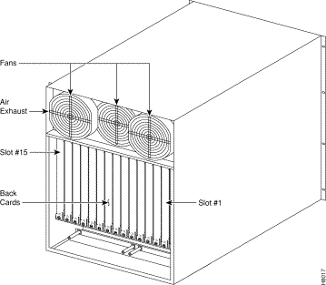
A fan assembly, with three six-inch 48 VDC fans is mounted on a tray at the rear of the BPX switch shelf (see Figure 2-2). Air for cooling the cards is drawn through an air intake grille located at the bottom in the front of the enclosure. Air passes up between the vertically-mounted cards and exhausts at the top, rear of the chassis. All unused slots in the front are filled with blank faceplates to properly channel airflow.
The primary power for a BPX switch node is -48 VDC which is bused across the backplane for use by all card slots. DC-to-DC converters on each card convert the -48V to lower voltages for use by the card. The -48 VDC input connects directly to the DC Power Entry Module (PEM). The DC Power Entry Module (see Figure 2-3) provides a circuit breaker and line filter for the DC input.
Nodes may be equipped with either a single PEM or dual PEMs for redundancy. They are mounted at the back of the node below the backplane. A conduit hookup box or an insulated cover plate is provided for terminating conduit or wire at the DC power input. It is recommended that the source of DC for the node be redundant and separately fused.

For applications requiring operation from an AC power source, an optional AC Power Supply Assembly and shelf is available. It provides a source of -48 VDC from 208/240 VAC input. A shelf, separate from the BPX switch shelf, houses one or two AC Power Supplies and mounts directly below the node cabinet. This provides a secure enclosure for the power supply assemblies (supplies cannot be removed without the use of tools).
Two of these supplies are usually operated in parallel for fail-safe redundant operation. The front of the AC Power Supplies for the BPX switch includes two green LEDs to indicate correct range of the AC input and the DC output for each individual supply (see Figure 2-4).

There are fifteen vertical slots in the front of the BPX switch enclosure to hold plug-in cards (see Figure 2-5). The middle two slots, slots number 7 and number 8, are used for the primary and secondary Broadband Controller Cards (BCC). The right-most slot, number 15, is used to hold the single Alarm/Status Monitor Card. The other twelve slots, number 1 through number 6 and number 8 through number 14, can be used for the Network Interface and Service Interface cards.

ATM transmits broadband information using fixed length, relatively small, 53-byte cells which are suitable for carrying both constant rate data (e.g., voice and video) as well as bursty data.
ATM evolved from the Broadband Integrated Services Digital Network (B-ISDN) standard, which in turn is an extension of ISDN. ISDN defines service and interfaces for public telecommunications networks. B-ISDN utilizes a 7-layer reference model similar to the Open Systems Interconnection (OSI) 7-layer architecture. ATM redefines the lower three levels as shown in Figure 2-6. These are the Physical Layer, the ATM layer, and the ATM Adaptation Layer (AAL).
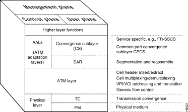
The physical layer is divided into two parts, the Transmission Convergence sub-layer and the Physical Medium sub-layer.
The Physical Medium sub-layer (PMD) handles processing specific to a particular physical layer, such as transmission rate, clock extractions, etc.
The Transmission Convergence sub-layer (TC) extracts the information content from the physical layer data format. This includes HEC generation and checking, extraction of cells from the data stream, processing of idle cells, etc.
The ATM layer processes ATM cells. The ATM cell consists of a 5-byte header and a 48-byte payload. The header contains the ATM cell address and other management information Figure 2-7.

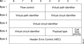
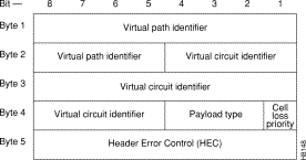
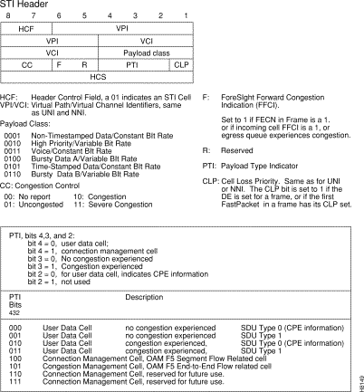
The most important fields in all three ATM cell header types are the Virtual Path Identifier (VPI) and a Virtual Circuit Identifier (VCI). The VPI identifies the route (path) to be taken by the ATM cell while the VCI identifies the circuit or connection number on that path. The VPI and VCI are translated at each ATM switch, they are unique only for a given physical link.
A 4-bit Generic Flow Control (GFC) field in the UNI header is intended to be used for controlling user access and flow control. At present, it is not defined by the standards committees and is generally set to all zeros.
A 3-bit Payload Type Indicator (PTI) field indicates the type of data being carried in the payload. The high-order bit is a "0" if the payload contains user information and is a "1" if it carries connection management information. The second bit indicates if the cell experienced congestion over a path. If the payload is user information, the third bit indicates if the information is from Customer Premises Equipment. The PTI field is identical for UNI/NNI/STI.
In the STI header (see Figure 2-10), the Payload Class is used to indicate various classes of service and BPX switch queues, e.g., Opticlass, the enhanced class of service feature of the BPX switch. The ForeSight Forward Congestion Indication, the F bit, is used by ForeSight for congestion status.
The Cell Loss Priority (CLP) bit follows the PTI bits in all header types. When set, it indicates that the cell is subject to discard if congestion is encountered in the network. For Frame Relay connections, depending on mapping considerations, the frame Discard Eligibility status is carried by the CLP bit in the ATM Cell. The CLP bit is also set at the ingress to the network for all cells carrying user data transmitted above the minimum rate guaranteed to the user.
Each ATM cell contains a two-part address, VPI/VCI, in the cell header. This address uniquely identifies an individual ATM virtual connection on a physical interface. VCI bits are used to identify the individual circuit or connection. Multiple virtual circuits that traverse the same physical layer connection between nodes are grouped together in a virtual path. The virtual path address is given by the VPI bits. The Virtual Path can be viewed as a trunk that carries multiple circuits all routed the same between switches
The VPI and VCI addresses may be translated at each ATM switch in the network connection route. They are unique only for a given physical link. Therefore, they may be reused in other parts of the network as long as care is taken to avoid conflicts.
The VCI field is 16 bits wide with UNI and NNI header types described earlier. This allows for a total possible 65, 535 unique circuit numbers. The UNI header reserves 8 bits for VPI (256 unique paths) while the NNI reserves 12 bits (4,096 unique paths) as it is likely that more virtual paths will be routed between networks than between a user and the network. The STI header reserves 8 bits for VCI and 10 bits for VPI addresses.
The purpose of the ATM Adaptation Layer (AAL) is to receive the data from the various sources or applications and convert, or adapt, it to 48-byte segments that will fit into the payload of an ATM cell. Since ATM benefits from its ability to accommodate data from various sources with differing characteristics, the Adaptation Layer must be flexible.
Traffic from the various sources have been categorized by the standards committees into four general classifications, Class A through Class D, as indicated in Table 2-1. This categorization is somewhat preliminary and initial developments have indicated that it may be desirable to have more than these initial four classes of service.
| Traffic Class | Class A | Class B | Class C | Class D |
|---|---|---|---|---|
Adaptation Layer (AAL) | AAL-1 | AAL-2 | AAL-3/4 AAL-5 | AAL-3/4 |
Connection Mode | Connection-oriented | Connection-oriented | Connection-oriented | Connectionless |
End-to-End Timing Relationship | Yes | Yes | No | No |
Bit Rate | Constant | Variable | Variable | Variable |
Examples | Uncompressed voice, constant bit-rate video | Compressed voice and video | Frame relay, SNA, TCP-IP, E-mail | SMDS |
Initially, four different adaptation layers (AAL1 through AAL4) were envisioned for the four classes of traffic. However, since AAL3 and AAL4 both could carry Class C as well as Class D traffic and since the differences between AAL3 and AAL4 were so slight, the two have been combined into one AAL3/4.
AAL3/4 is quite complex and carries a considerable overhead. Therefore, a fifth adaptation layer, AAL5, has been adopted for carrying Class C traffic, which is simpler and eliminates much of the overhead of the proposed AAL3/4. AAL5 is referred to as the Simple and Efficient Adaptation Layer, or SEAL, and is used for Frame Relay data.
Since ATM is inherently a connection-oriented transport mechanism and since the early applications of ATM will be heavily oriented towards LAN traffic, many of the initial ATM products are implemented supporting the Class C Adaptation Layer with AAL5 Adaptation Layer processing for carrying Frame Relay traffic.
Referring back to Figure 2-6, the ATM Adaptation Layer consists of two sub-layers:
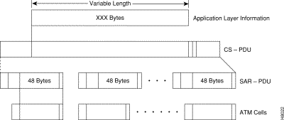
Data is received from the various applications layers by the Convergence Sub-Layer and mapped into the Segmentation and Reassembly Sub-Layer. User information, typically of variable length, is packetized into data packets called Convergence Sublayer Protocol Data Units (CS-PDUs). Depending on the Adaptation Layer, these variable length CS-PDUs will have a short header, trailer, a small amount of padding, and may have a checksum.
The Segmentation and Reassembly Sub-Layer receives the CS-PDUs from the Convergence Sub-Layer and segments them into one or more 48-byte SAR-PDUs, which can be carried in the 48-byte ATM information payload bucket. The SAR-PDU maps directly into the 48-byte payload of the ATM cell transmitted by the Physical Layer. Figure 2-11 illustrates an example of the Adaptation Process.
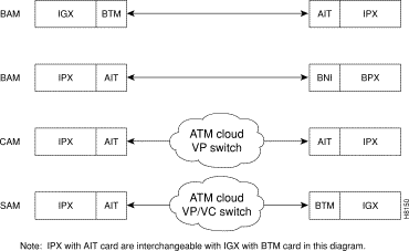
The IPX switch connects to a BPX switch or other ATM switch via an AIT/BTM T3 or E3 trunk. the IGX switch also connects to an ATM trunk via the UXM card. The AIT(IPX switch) or BTM (IGX switch) can operate in several different addressing modes selected by the user (see Table 2-2 and Figure 2-12). To allow the IPX switch or IGX switch to be used in mixed networks with other ATM switches, there are two other addressing modes available, Cloud Addressing Mode (CAM) and Simple Addressing Mode (SAM).
In the BPX switch Addressing Mode (BAM), used for all Cisco WAN switching networks, the system software determines VPI and VCI values for each connection that is added to the network. The user enters the beginning and end points of the connection and the software automatically programs routing tables in each node that will carry the connection to translate the VPI/VCI address. The user does not need to enter anything more. This mode uses the STI header format and can support all of the optional Cisco WAN switching features.
In the Simple Addressing Mode (SAM), the user must manually program the path whole address, both VPI and VCI values.
The Cloud Addressing Mode (CAM) is used in mixed networks where the virtual path addresses are programmed by the user and the switch decodes the VCI address. Both CAM and SAM utilize the UNI header type.
| Addressing Mode | Hdr. Type | Derivation of VPI/VCI | Where Used |
|---|---|---|---|
BAM-BPX switch Addressing Mode | STI | VPI/VCI = Node Derived Address | Between IPX switch (or IGX switch) and BPX switches, or between IPX switch (or IGX switch) nodes. |
CAM— | UNI | VPI = User Programmed | IPX switch to IPX switch (or IGX switch) connections over networks using ATM switches that switch on VPI only. VPI is manually programmed by user. Terminating IPX switch converts VCI address to FastPacket address. |
SAM— | UNI | VPI/VCI = User Programmed | IPX switch to IPX switch (or IGX switch) connections over networks using ATM switches that switch where all routing is manually programmed by user, both VPI and VCI. |
A specialized adaptation that is of particular interest to users of Cisco equipment is the adaptation of IPX switch FastPackets to ATM cells. There are a large number of narrowband IPX switch networks currently in existence that are efficiently carrying voice, video, data, and Frame Relay. A means must be provided to allow these networks to grow by providing a migration path to broadband.
Since FastPackets are already a form of cell relay, the adaptation of FastPackets to ATM cells is relatively simple.
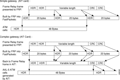
With the Simple Gateway protocol, the AIT card in the IPX switch (or BTM in the IGX switch) loads 24-byte FastPacket cells into ATM cells in ways that are consistent with each application. (Each of the two FastPacket cells loaded into the ATM Cell is loaded in its entirety, including the FastPacket header.) For example, two FastPackets can be loaded into one ATM cell provided they both have the same destination. This adaptation is performed by the IPX switch AIT card or the IGX switch BTM card.
The AIT (or BTM) is configured to wait a given interval for a second FastPacket to combine in one ATM cell for each FastPacket type. The cell is transmitted half full if the wait interval expires. High priority and non-time stamped packets are given a short wait interval. High priority FastPackets will not wait for a second FastPacket. The ATM trunk interface will always wait for Frame Relay data (bursty data) to send two packets. NPC traffic will always have two FastPackets in an ATM cell.
Starting with Release 8.1, with the Complex Gateway capability, the FRSM card in the MGX 8220, the AIT card in the IPX switch (or BTM card in the IGX switch) streams the Frame Relay data into ATM cells, cell after cell, until the frame has been completely transmitted. Since only the data from the FastPacket is loaded, the Complex Gateway is an efficient mechanism. Also, discard eligibility information carried by the Frame Relay bit is mapped to the ATM cell CLP bit, and vice versa. See Chapter 13 for further information on Frame Relay to ATM interworking. A comparison of the simple gateway and complex gateway formats is shown in Figure 2-13.
There are four major groups in the BPX switch. These are listed in Table 2-3.
Table 2-3 lists these groups and their components along with a brief description of each.
| Card | Card Name | Where |
|---|---|---|
BPX- | Common Core Group |
|
BPX-BCC-32 | Broadband Controller Card, operates with versions of System Software Rel. 7.0 and above, and requires 32 Mbyte RAM for 8.1 and later software. For redundancy configuration, installed as a pair of BCC-32s. (System operation equivalent to BCC-3.) | Front |
BPX-BCC-bc | Back card (also known as LM-BCC) used only with the BCC-32. | Back |
BPX-BCC-3 | Broadband Controller Card, operates with 7.X software versions 7.2.84 and above, and with 8.X System Software versions 8.1.12 and above. For redundancy configuration, installed as a pair of BCC-3s. (System operation equivalent to BCC-32.) | Front |
BPX-BCC-3-64 | Broadband Controller Card, enhanced BCC-3. Note: BCC-3-64 or BCC-4 required to support VSI and MPLS. |
|
BPX-BCC-4 | Broadband Controller Card, operates with 8.4 software and above. For redundancy configuration, installed as a pair of BCC-4s. Provides 64 Mbyte of RAM and above. Supports up to 19.2 Gbps performance of BXM cards. Note: BCC-3-64 or BCC-4 required to support VSI and MPLS | Front |
BPX-BCC-3-bc | Back card (also known as LM-BCC) used with BCC-3 or BCC-4. | Back |
BPX-ASM | Alarm/Status Monitor Card. | Front |
BPX-ASM-BC | Line Module - Alarm/Status Monitor. | Back |
| Network Interface Group |
| |
BPX-BXM-T3-8 BPX-BXM-E3-8 BP:X-BXM-T3-12 BPX-BXM-E3-12 | T3/E3 card with 8 or 12 ports. Card is configured for use in either network interface or service access (UNI) mode and with either a T3 or E3 interface. | Front |
BPX-T3/E3-BC | Backcard for use with a BXM-T3/E3-8 or BXM-T3/E3-12 | Back |
BPX-BXM-155-4 BPX-BXM-155-8 | BXM OC-3 cards with 4 or 8 OC-3/STM-1ports, respectively. Card is configured for use in either network interface or service access (UNI) mode. | Front |
BPX-MMF-155-4-BC BPX-SMF-155-4-BC BPX-SMFLR-155-4-BC | Backcards for BXM-155-4. | Back |
BPX-MMF-155-8-BC BPX-SMF-155-8-BC BPX-SMFLR-155-8-BC | Backcards for BXM-155-8.
| Back |
BPX-BXM-622 BPX-BXM-622-2 | OC-12 card with 1or 2 OC-12/STM-4ports. Card is configured for use in either network interface or service access (UNI) mode. | Front |
BPX-BME | Used for multicast connections. Used with SMF-622-2 backcard with port 1 looped to port 2, transmit to receive, and receive to transmit. |
|
BPX-SMF-622 BPX-SMFLR-622 BPX-XLR-622-BC | Backcards for BXM-622. The XLR card supports a 1500nm interface | Back |
BPX-SMF-622-2-BC BPX-SMFLR-622-2-BC BPX-SMFLR-622-2-BC | Backcards for BXM-622-2 and BME (BME typically would use SMF-622-2). | Back |
BPX-BME | Used for multicast connections. Used with SMF-622-2 backcard with port 1 looped to port 2, transmit to receive, and receive to transmit. | Back |
BPX-BNI-3-T3 | Broadband Network Interface Card (with 3 T3 Ports). | Front |
BPX-T3-BC | Line Module - used with BNI-T3 for 3 physical T3 ports. (Configured for 3 ports) | Back |
BPX-BNI-3-E3 | Broadband Network Interface Card (with 3 E3 Ports). | Front |
BPX-E3-BC | Line Module - used with BNI-E3 for 3 physical E3 ports. (Configured for 3 ports). | Back |
BPX-BNI-155 | Broadband Network Interface Card (with 2 OC3c/STM-1 ports). | Front |
BPX-SMF-2-BC | OC3/STM-1 Interface Card, single mode fiber optic, used with either BNI-155 or ASI-155 front card. | Back |
BPX-SMFLR-2-BC | OC3/STM-1 Interface Card, single mode fiber optic long range, used with either BNI-155 or ASI-155. | Back |
BPX-MMF-2-BC | OC3/STM-1 Interface Card, multi-mode fiber optic (1 x 9 LED), used with either BNI-155 or ASI-155 front card. | Back |
| APS Backcards and APS Redundant Backplane |
|
The APS 1+1 feature requires two BXM front cards, an APS redundant frame assembly, and two redundant type BXM backcards. The types of redundant backcard and backplane sets are:
Each of the listed model numbers includes two single backcards and one mini-backplane. | ||
The single backcards and mini-backplane can be ordered as spares. Their model numbers are: BPX-RDNT-BP= (common backplane for all redundant APS backcards) BPX-LR-155-8R-BC= (for BPX-RDNT-LR-155-8) BPX-LR-622-R-BC= (for BPX-RDNT-LR-622 BPX-SMF-155-4R-BC= (for BPX-RDNT-SM-155-4) BPX-SMF-155-8R-BC= (for BPX-RDNT-SM-155-8) BPX-SMF-622-R-BC= (for BPX-RDNT-SM-622) BPX-SMF-622-2R-BC= (for BPX-RDNT-SM-622-2 | ||
| Service Interface Group |
|
|
|
|
BPX-ASI-1-2T3 | ATM Service Interface Card (with 2 usable T3 ports). | Front |
BPX-T3-BC | Line Module - used with ASI-1-2T3 for 2 physical T3 ports. (Configured for 2 ports) | Back |
BPX-ASI-1-2E3 | ATM Service Interface Card (with 2 usableE3 ports). | Front |
BPX-E3-BC | Line Module - used with BNI-E3 for 2 physical E3 ports. (Configured for 2 ports) | Back |
BPX-ASI-155 | ATM Service Interface Card (with 2 OC3c/STM-1 ports). | Front |
BPX-SMF-2-BC | OC3/STM-1 Interface Card, SMF (single mode fiber optic) MMF (1x9 LED), used with either BNI-155 or ASI-155 front card. | Back |
BPX-MMF-2-BC | OC3/STM-1 Interface Card, multi-fiber mode (1 x 9 LED), used with BNI-155 or ASI-155. | Back |
BPX-SMFLR-2-BC | OC3/STM-1 Interface Card, single mode fiber optic long range, used with either BNI-155 or ASI-155. | Back |
| Power Supply Group |
|
| 48 Volt DC Power Supply |
|
| Optional AC Power Supply |
|
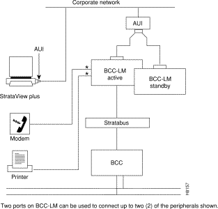
At least one node in the network (or network domain if a structured network) must include a Strata-View Plus network management station (see Figure 2-14). A Y-cable may be used to connect the LAN ports on the primary and secondary BCC Line Modules, through an AUI to the LAN network, as only one BCC is active at a time. The serial Control port may be connected to a dial-in modem for remote service support or other dial-up network management access. The serial Auxiliary port is used for outgoing data only, for example, for connection to a printer.
![]()
![]()
![]()
![]()
![]()
![]()
![]()
![]()
Posted: Sun Jan 14 18:41:37 PST 2001
All contents are Copyright © 1992--2001 Cisco Systems, Inc. All rights reserved.
Important Notices and Privacy Statement.