|
|

This appendix illustrates typical cable management and space requirements for various system configurations in the Cisco cabinet. It also contains a table with the height of Cisco components in inches, centimeters, and rack-mount units (RMUs). This can help in the calculation of height requirements for individual setups. The last illustration shows the bracket installation in the Cisco (for a BPX switch, in this case). The information is grouped as follows:
Table A-1 lists Cisco cabinet dimensions and the heights of components that may be installed in the cabinet.
| Components | Unit Height | ||
|---|---|---|---|
| Inches | CM | RMUs | |
MGX 8220 Card Cage | 8.75 | 22.225 | 5 |
MGX 8220 AC Power Supply shelf | 5.25 | 13.335 | 3 |
MGX 8220 Booster Fan Assembly | 3.5 | 8.89 | 2 |
MGX 8220 Cooling Assembly | 5.25 | 13.335 | 3 |
MGX 8220 Exhaust Plenum | 3.5 | 8.89 | 2 |
BPX switch AC Power Supply shelf | 5.25 | 13.335 | 3 |
BPX switch Card Cage | 22.75 | 57.785 | 13 |
IGX switch AC Power Supply shelf | 5.25 | 13.335 | 3 |
IGX switch Booster Fan Assembly | 3.5 | 8.89 | 2 |
IGX switch Card Cage | 17.5 | 44.45 | 10 |
IGX switch Cooling Assembly | 5.25 | 13.335 | 3 |
IGX switch Exhaust Plenum | 3.5 | 8.89 | 2 |
IGX 8410 switch | 24.5 | 62.23 | 14 |
DAS, VNS, and ESP | 5.25 | 13.335 | 3 |
| Cabinet | Unit Height | ||
| Inches | CM | RMUs | |
Cisco Cabinet | 71.75 | 1822.45 | 41 |
Figure A-1 shows a back view of an empty Cisco cabinet.
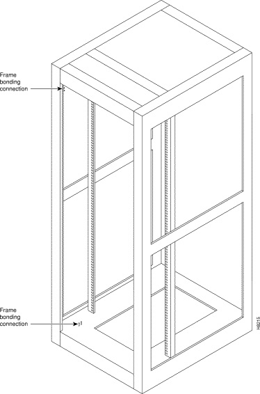 Back View of Empty Cisco Cabinet
Figure A-2 shows a typical cable management configuration for an IGX-32 switch in a Cisco cabinet.
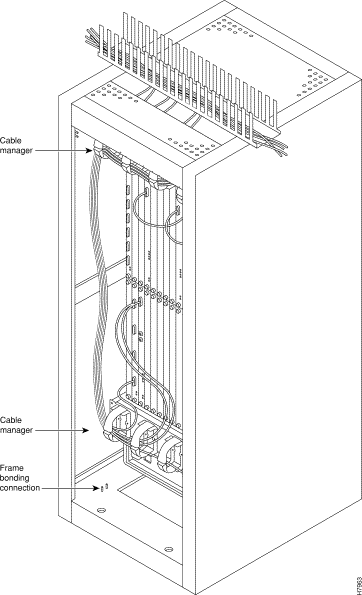
Figure A-3 through Figure A-9 show various BPX switch configurations.
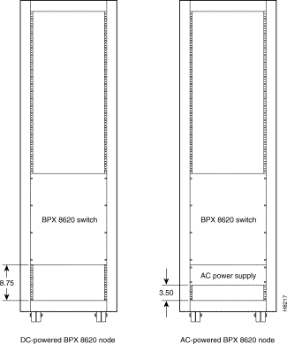 Single BPX Switch, DC and AC Systems
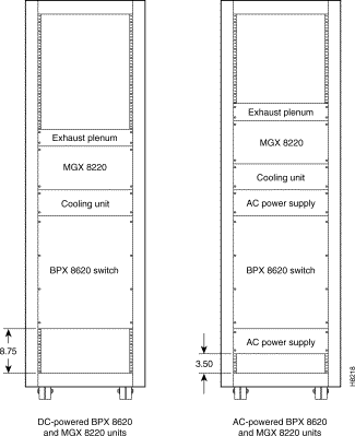 Single BPX Switch and MGX 8220, DC and AC Systems
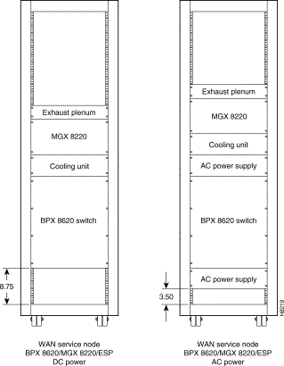 BPX Switch, MGX 8220, and ESP, DC and AC Systems

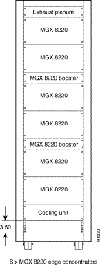 Six MGX 8220, DC System
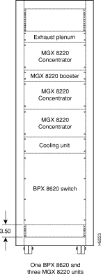 BPX Switch with Three MGX 8220s, DC System
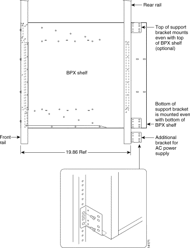 Mounting Brackets (BPX switch), Standard Configuration
Figure A-10 through Figure A-12 show various IGX switch configurations.
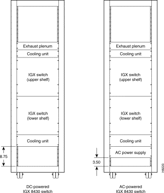 IGX 8430 Switch, DC and AC Systems
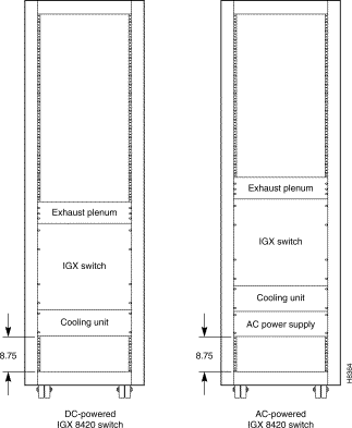 Single IGX 8420 Switch, DC and AC Systems
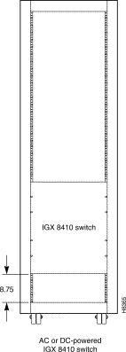 Single IGX 8410 switch, DC or AC System
![]()
![]()
![]()
![]()
![]()
![]()
![]()
![]()
Posted: Thu Jul 26 18:04:55 PDT 2001
All contents are Copyright © 1992--2001 Cisco Systems, Inc. All rights reserved.
Important Notices and Privacy Statement.