|
|

This chapter contains an overview of multicasting, a description of the BME card used on the BPX switch for multicasting for PVCs, and configuration information.
This chapter contains the following:
The BME provides multicast services in the BPX switch. It is used in conjunction with a two-port OC-12 backcard.
Multicasting point-to-multipoint services meets the demands of users requiring virtual circuit replication of data (Frame Relay and ATM) performed within the network. Some examples of functions benefiting from multicasting are:
Multicasting point-to-multipoint connections benefits include:
Root connections and leaf connections can be added in any order:
Root and leaf connections can be deleted in any order.
Root can be deleted and replaced with a new root.
Cisco WAN Manager management includes the following functions:
Cables are connected between port 1 and port 2 of the backcard, transmit to receive and receive to transmit.
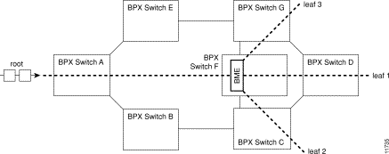
Figure 18-1 shows a BME with a single root input multicasting with 3 leaves. The root connection can be added at a BPX switch (BPX switch A) distant from where the traffic is replicated by the BME card (BPX switch F) and routed through a number of BPX nodes. Similarly, the leaves can be routed from the multicasting node through a number of nodes before reaching their destination.
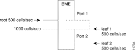
As an example of how traffic appears on the BME, if there is one root at port 1 with two leaves at port 2, and traffic is passed on the root at 500 cells/sec, then one should see an egress port stat of 1000 cell/sec on port 1 and an ingress port stat of 1000 cells/sec on port 2, as shown in Figure 18-2.
Two multicasting groups are shown in Figure 18-3. For purposes of the illustration only a few leaves are shown for each connection. However, as described previously, each multicasting group could contain up to 8064 connections. Also, in this example, the two connections with a VCI of 0 each define a multicasting root connection. Their VPI defines a broadcasting group. For example, one group is defined by 2.1.70.0, where the VCI of zero defines the root connection to a BME, and the VPI of 70 defines a group. All the leaves in that group are of the form 2.2.70.x. The other group is defined by 2.2.80.0, where the VCI of zero defines the root connection to a BME, and the VPI of 80 defines a group. All the leaves in that group are of the form 2.1.80.x.
| Group 2.1.70.x | Action | Command |
|---|---|---|
at bpx switch_F, | add input to root | addcon 2.1.70.0 bpx switch_A 1.1.80.100 c 500 * * * |
at bpx switch_F, | add leaf 1 | addcon 2.2.70.101 bpx switch_D 6.1.100.50 c 500 * * * |
at bpx switch_F, | add leaf 2 | addcon 2.2.70.100 bpx switch_C 4.3.50.60 c 500 * * * |
at bpx switch_F, | add leaf 3 | addcon 2.2.70.102 bpx switch_G 3.4.55.75 c 500 * * * |
| Group 2.2.80.x | ||
at bpx switch_F, | add input to root | addcon 2.2.80.0 bpx switch_B 10.1.233.400 v 4000 * * * |
at bpx switch_F, | add leaf 1 | addcon 2.1.80.201 bpx switch_E 13.1.78.900 v 4000 * * * |
at bpx switch_F, | add leaf 2 | addcon 2.1.80.100 bpx switch_E 14.1.100.40 v 4000 * * * |
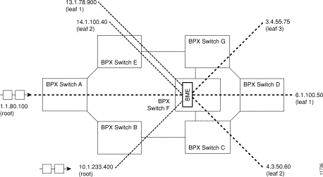
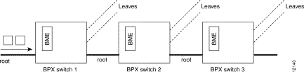
Figure 18-4 shows an example of a multi-segment multicast connection where a leaf connection from one BME can become a root connection for another BME. This capability allows the users to configure multi-segment multicast tree topologies.
Channel statistics are available for leaf connections on the BME end. However, channel statistics are not available for the root connection on the BME end.
For the example in Figure 18-5, execute the following commands to display channel statistics for the leaf connections:
For the example in Figure 18-5, the following command will not display channel statistics (because 5.1.75.0 is a root connection):

Policing is supported on all leaf connections on the BME end.
All policing types available on the BXM are available on the BME leaves.
No policing functionality is available on the root connection on the BME end.
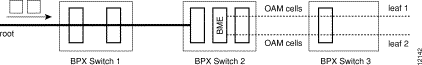
OAM cells coming into the root are multicast into the leaves along with data, as shown in Figure 18-6.
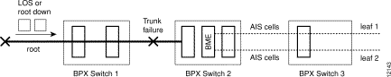
AIS cells are automatically generated on the leaves, as shown in Figure 18-7, when:
BME cards can be set up to provide hot standby backup. Both cards are set up with port 1 connected to port 2 on the same card to provide the multicasting connection, transmit to receive and receive to transmit. There is no Y-cabling connection between the cards, and they do not have to be adjacent to each other.
The addyred command is used to enable hot standby backup between the cards. The addyred command must be used before any connections are added to the active card. The command will be rejected if used after connections have been added to the active card.
If the multicast tree has a large number of leaf connections, for example, 3000, then the cnfportq command should be used to configure the Qbin threshold to be greater than needed for half the number of leaves so as to assure that the multicast group will have no discards. The Qbin default depth is about 1200 cells.
The following is a Qbin example using the cnfportq command:
j4b            VT    SuperUser     ~ BPX 15    9.2      Nov. 24 1998 16:59 PST
Port:       3.2     [ACTIVE  ]
Interface:          LM-BXM
Type:               NNI
Speed:              1412830 (cps)
SVC Queue Pool Size:          0
CBR Queue Depth:              1200
CBR Queue CLP High Threshold: 80%
CBR Queue CLP Low Threshold:  60%
CBR Queue EFCI Threshold:     80%
VBR Queue Depth:              10000   UBR/ABR Queue Depth:               40000
VBR Queue CLP High Threshold: 80%     UBR/ABR Queue CLP High Threshold:  80%
VBR Queue CLP Low Threshold:  60%     UBR/ABR Queue CLP Low Threshold:   60%
VBR Queue EFCI Threshold:     80%     UBR/ABR Queue EFCI Threshold:      30%

This Command: cnfportq 3.2
SVC Queue Pool Size [0]:
Virtual Terminal      CD
BME
The BPX switch must be initially installed, configured, and connected to a network.
Following this, multi-casting connections can be added to the BPX switch.
![]()
![]()
![]()
![]()
![]()
![]()
![]()
![]()
Posted: Thu Jul 26 18:03:49 PDT 2001
All contents are Copyright © 1992--2001 Cisco Systems, Inc. All rights reserved.
Important Notices and Privacy Statement.