|
|

This chapter contains a description of the BPX network interface (trunk) cards, including the Broadband Network Interface (BNI) and associated backcards.
This chapter contains the following:
The BPX network interface group of cards provides the interface between the BPX and the ATM network (Figure 4-1). The BNI series of cards (DS3, E3, and OC3) are described in this chapter. The BXM card trunk operation is briefly described in this chapter with additional information provided in a later chapter. The BXM cards may be configured for either trunk or service (port UNI) mode. In trunk mode they provide BPX network interfaces.
The BXM card sets supports T3/E33, OC-3/STM-1, or OC-12/STM-4 interfaces, and provide the capacity to meet the needs of emerging bandwidth driven applications. The BXM cards provide high speed ATM connectivity, flexibility, and scalability. The card sets are comprised of a front card that provides the processing, management, and switching of ATM traffic and of a back card that provides the physical interface for the card set.
A BXM port may be configured to operate as either a trunk or UNI port. The BXM OC-12 back cards support either Single Mode Fiber (SMF) or Single Mode Fiber Long Reach (SMFLR). The BXM OC-3 back cards support either Multi-Mode Fiber (MMF), Single Mode Fiber (SMF), or Single Mode Fiber Long Reach (SMFLR). The BXM-T3/E3 supports T3 1.544 Mbps and E3 34.368 Mbps interfaces.
For a further description of the BXM cards refer to Chapter 6, BXM T3/E3, 155, and 622.
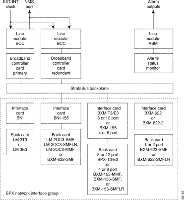
The BNI-T3 and BNI-E3 interface the BPX with ATM T3 and E3 broadband trunks, respectively. These ATM trunks may connect to either another BPX, an IPX equipped with an AIT card, or an AXIS Shelf.
The BNI-3T3 back card provides three DS3 interfaces on one card while the BNI-E3 back card provides three E3 interface ports. The BNI back card types are very similar differing only in the electrical interface and framing. Any of the 12 general purpose slots can be used to hold these cards. Each BNI operates as a pair with a corresponding Line Module back card.
A summary of features for the BNI cards include:
The BNI T3 and E3 cards are functionally alike except for the two different electrical interfaces. Refer to Figure 4-2 illustrating the main functional blocks in the BNI-3T3 card.
The DS3 port interface on the BNI-T3 card is the DS3 Function Block, a Physical Layer Protocol Processor (PLPP) custom semiconductor device, which implements the functions required by the DS3 PLCP as defined in various AT&T(TM) technical advisories. This VLSI device operates as a complete DS3 transmitter/receiver. Each BNI-3T3 has three of these devices, one for each of the DS3 ports on the card.
In the transmit direction (from the BPX switching matrix towards the transmission facility, referred to as egress), the BNI performs the following functions:
In the receive direction (from the transmission facility towards the BPX switching matrix, sometimes referred to as ingress), the BNI performs the following functions:

Some of the functions performed by the PLPP in the BNI-3T3 include:
In the BNI-3E3 the PLPP is replaced by a G.804 framer. The E3 framer obtains end-to-end synchronization on the Frame Alignment bytes. And a E3 transmitter/receiver replaces the DS3 transmitter/receiver for the BNI-3E3.
Another major BNI function is queuing of the ATM cells waiting to be transmitted to the network trunk. This is controlled by the Queue Service Engine. There are 32 queues for each of the three ports to support 32 classes of service, each with its programmable parameters such as minimum bandwidth, maximum bandwidth, and priority. Queue depth is constantly monitored to provide congestion notification (EFCN) status. The Queue Service Engine also implements a discard mechanism for the cells tagged with Cell Loss Priority.
The destination of each cell is contained in the Virtual Path Identifier/Virtual Circuit Identifier VPI/VCI) field of the cell header. This is translated to a Logical Connection Number via table lookup in the Network Address Table. Both terminating and through connections can coexist on a port.
A Serial Interface Module (SIM) provides cell interface to the StrataBus backplane. This operates at 800 Mbps. It provides a serial-to-parallel conversion of the data and loopback and pseudo-random bit generation for test purposes.
The transmit bandwidth can be throttled down for certain applications. For example, when interfacing with an IPX E3 ATM Trunk Card, the trunk transmit rate is limited to 40,000 cells/second. If a T2 trunk adapter is used, the trunk transmit rate is limited to 14,000 cells/second.
There are two types of self-tests that may be performed. A non-disruptive self test is automatically performed on a routine basis. A more complete, disruptive test may be initiated manually when a card failure is suspected. If the card self-test detects a failure, the card status LEDs displays an indication of the failure type (see Table 4-5).
Several loopback paths are provided. A digital card loopback path, used by the node for self-test, loops the data at the serial DS3 or E3 interface back towards the node. A digital line loopback loops the data at the electrical transmitter/receiver at the card output. Internally, the PLPP circuit in the BNI-T3 has several loopbacks for use by diagnostic routines.
There are several loopback paths within the BNI for testing. A digital loopback at the DS3 or E3 transmitter/receiver to check both the transmit and receive signal paths in the near-end BNI card. These loopbacks loop the signal in both directions, towards the StrataBus as well as towards the output. Therefore, they can be used to support both near end and far end maintenance loopback testing. On the BNI-3T3, there is a digital loopback capability to the PLPP processor used for the internal self test to basically check the operation of the signal processor.
Once a trunk has been assigned to a BNI card but before it is made active (upped), it is put in a loopback mode and a diagnostic test is continuously performed. This loopback is disruptive so it cannot be performed on a card that has an active trunk. This diagnostic test checks the data path through the BNI out to the BCC, through the switch matrix, and back to the BNI. Active trunks are constantly checked by the Communications Fail test routine which is part of system software.
The lower section of the BNI front panel (Figure 4-3) has a three-section, multicolored LED to indicate the card status. The card status LED is color-coded as indicated in Table 4-1. At the upper portion of the front panel, there is a three-section multicolored LED to indicate the status of the three ports on the BNI. Types of failures are indicated by various combinations of the card status indicators as indicated in Table 4-2.
| Status | LED color | Status Description |
|---|---|---|
Port | off | Trunk is inactive and not carrying data. |
| green | Trunk is actively carrying data. |
| yellow | Trunk is in remote alarm. |
| red | Trunk is in local alarm. |
Card | green (act) | Card is on-line and one or more trunks on the card have been upped. If off, card may be operational but is not carrying traffic. |
| yellow (stby) | Card is off-line and in standby mode (for redundant card pairs). May not have any upped trunks. If blinking, indicates card firmware or configuration data is being updated. |
| red (fail) | Card failure; card has failed self-test and/or is in a reset mode. See Table 4-5 for more information. |

| act | stby | fail | Failure Description |
|---|---|---|---|
on | off | on | Non-fatal error detected; card is still active. |
off | on | on | Non-fatal error detected; card is in standby mode. |
off | blinking | on | Fatal error detected; card is in a reboot mode. |
on | on | on | Card failed boot load and operation is halted. |
The Line Modules for the BNI-T3 and BNI-E3 front cards are back cards used to provide a physical interface to the transmission facility. The LM-3T3 is used with the BNI-T3 and the LM-3E3 with the BNI-3E3. The Line Module connects to the BNI through the StrataBus midplane. Two adjacent cards of the same type can be made redundant by using a Y-cable at the port connectors. All three ports on a card must be configured the same.
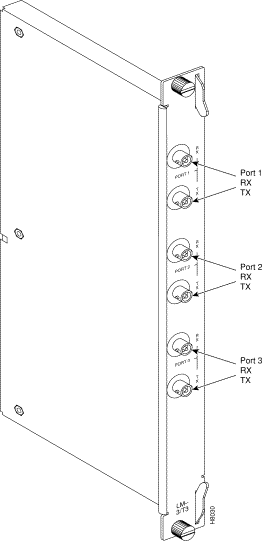
Refer to Figure 4-4, Figure 4-5, and Table 4-3 which describe the faceplate connectors of the LM-3T3 and LM-3E3. There are no controls or indicators.
The LM-3T3 provides the following features:
A final node loopback is found at the end of the LM-3T3 or LM-3E3 card. This is a metallic loopback path that uses a relay contact closure. It is a near-end loopback path only; the signal is looped at the final output stage back to circuits in the node receive side. It is only operated when the corresponding front card is in standby.
| No. | Connector | Function |
|---|---|---|
1. | PORT 1 RX - TX | BNC connectors for the transmit and receive T3/E3 signal to/from ATM trunk #1. |
2. | PORT 2 RX - TX | BNC connectors for the transmit and receive T3/E3 signal to/from ATM trunk #2. |
3. | PORT 3 RX - TX | BNC connectors for the transmit and receive T3/E3 signal to/from ATM trunk #3. |

The BNI-155 interfaces the BPX with ATM OC3/STM-1 broadband trunks. The ATM trunk may connect to either another BPX or customer CPE equipped with an ATM OC3/STM-1 interface.
There are three BNI-155 back cards, the LM-2OC3-SMF for single-mode fiber intermediate range, the LM-2OC3-SMFLR for single-mode fiber long range, and the LM-2OC3-MMF for multi-mode fiber. Any of the 12 general purpose slots can be used to hold these cards. These backcards may also be used with the ASI-155.
A summary of features for the BNI-155 cards include:
Egress
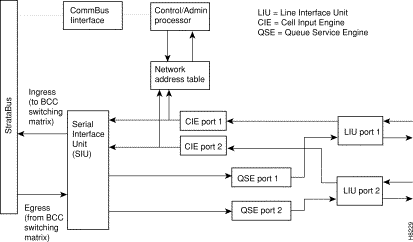
In the transmit direction (from the BPX switching matrix towards the transmission facility, referred to as egress), the BNI performs the following functions (Figure 4-6):
Ingress
In the receive direction (from the transmission facility towards the BPX switching matrix, referred to as ingress), the BNI performs the following functions (Figure 4-6):
In the egress direction, the BNI-155 has 2 Queue Service Engine (QSEs) which provide each of the ports with 12 programmable queues with selectable parameters such as minimum bandwidth, priority, and maximum bandwidth. The BNI queues are based on a class of service algorithm. The BNI supports the following trunk queues:
In the ingress direction, the BNI-155 has 2 Cell Input Engines (CIEs) that convert the incoming cell headers to the appropriate connection ID based on input from a Network Address Table.
The Serial Interface Unit (SIU) provides the BNI with an 800 Mbps cell interface to the StrataBus. It provides serial-to-parallel conversion of data, along with loopback and test signal generation capabilities.
The Line Interface Unit (LIU)performs the following ingress functions:
The Line Interface Unit (LIU) performs the following egress functions:
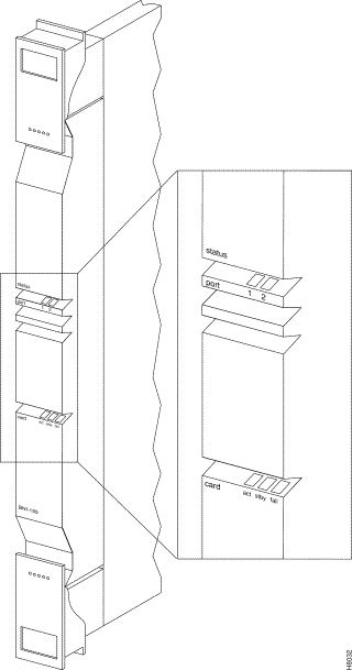
The BNI-155 front panel (Figure 4-7) has a three-section, multicolored "card" LED to indicate the card status. The card status LED is color-coded as indicated in Table 4-4. A three-section multicolored "port" LED indicates the status of the two ports on the BNI-155. Types of failures are indicated by various combinations of the card status indicators as indicated in Table 4-5.
| Status | LED color | Status Description |
|---|---|---|
port | off | Trunk is inactive and not carrying data. |
| green | Trunk is actively carrying data. |
| yellow | Trunk is in remote alarm. |
| red | Trunk is in local alarm. |
card | green (act) | Card is on-line and one or more trunks on the card have been upped. If off, card may be operational but is not carrying traffic. |
| yellow (stby) | Card is off-line and in standby mode (for redundant card pairs). May not have any upped trunks. If blinking, indicates card firmware or configuration data is being updated. |
| red (fail) | Card failure; card has failed self-test and/or is in a reset mode. See Table 4-5 for more information. |
| act | stby | fail | Failure Description |
|---|---|---|---|
on | off | on | Non-fatal error detected; card is still active. |
off | on | on | Non-fatal error detected; card is in standby mode. |
off | blinking | on | Fatal error detected; card is in a reboot mode. |
on | on | on | Card failed boot load and operation is halted. |
The Line Modules for the OC3 BNI cards are back cards used to provide a physical interface to the transmission facility. There are three types, a single-mode fiber intermediate range, single-mode fiber long range, and a multi-mode fiber backcard. The Line Modules connect to the BNI through the StrataBus midplane.
For connector information, refer to Figure 4-8 and Table 4-6 for the LM-OC3-SMF and to Figure 4-9 and Table 4-7 for the LM-OC3-MMF. The LM-OC3-SMFLR uses the same type of connectors as the LM-OC3-SMF.
| No. | Connector | Function |
|---|---|---|
1. | PORT | FC-PC connectors for the transmit and receive OC3 signal to/from ATM trunk #1. |
2. | PORT | FC-PC connectors for the transmit and receive OC3 signal to/from ATM trunk #2. |
| No. | Connector | Function |
|---|---|---|
1. | PORT | Duplex SC connectors for the transmit and receive OC3 signal to/from ATM trunk #1. |
2. | PORT | Duplex SC connectors for the transmit and receive OC3 signal to/from ATM trunk #2. |


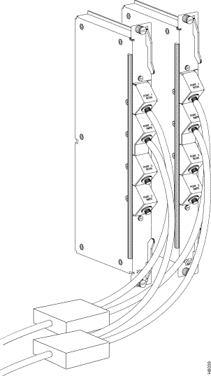
The LM-OC3-SMF (Model SMF-2-BC) backcards may be Y-cabled for redundancy using the Y-Cable splitter shown in Figure 4-10. The cards must be configured for Y-Cable redundancy using the addyred command.
![]()
![]()
![]()
![]()
![]()
![]()
![]()
![]()
Posted: Wed Jan 17 21:22:34 PST 2001
All contents are Copyright © 1992--2001 Cisco Systems, Inc. All rights reserved.
Important Notices and Privacy Statement.