|
|

For the BCC-3, the backcard is the BCC-3-bc. For the BCC-32, the backcard is the BCC-bc (also known as the BCC backcard). The BCC-3 and the BCC-32 are functionally interchangeable, but both BCCs in a node should be of the same type. The backcards for the Broadband Controller Card serve as an interface between the BPX node and the BPX network management system. The backcard provides the following interfaces:
The face plate connectors are described in Table 2-5 and shown in Table 2-17. There is a XFER TMG port on the face plate for providing a clock output. There are also two EXT TMG inputs for 1.544 MHz for T1 systems and 2.048 MHz for CEPT systems.
| BCC-C Connector | BCC-C Function | BCC-3-BC Connector | BCC-3-C Function |
|---|---|---|---|
CONTROL | A DB25 connector for a VT100 or equivalent terminal for a basic terminal connection using command line interface commands. Can also be connected to a dial-in modem for remote service support or other network management dial-up access. This is a bidirectional RS232 communications port. This is not used for SV+ Network Management; the LAN connector is used for SV+ Network Management. | CONTROL | Same as BCC-C CONTROL connector |
AUXILIARY | A DB25 connector for a system printer. This is a one-way, RS232 outgoing port. | AUXILIARY | Same as BCC-C LAN connector |
XFER TMG | DB15 connector for supplying a 80 kHz timing signal output that is synchronized to the BPX system clock. Could be used to synchronize a co-located IPX. | LAN | Same as BCC-C EXT TMG connector |
EXT TMG | A 75-ohm/120-ohm BNC connection for E1 clock input in lieu of using connector #5. | EXT TMG | Same as BCC-C EXT TMG BNC connector |
EXT TMG | DB15 connector for a primary and optional redundant external source of system clock at either 1.544 or 2.048 MHz. | EXT 1 TMG | Same as BCC-C EXT TMG DB15 connector |
LAN | A DB15 Ethernet LAN connection for connecting to a StrataView Plus NMS. A terminal or NMS other than SV+ can also be connected to the BPX LAN port via Ethernet. However only the SV+ NMS provides full management configuration and statistics capabilities via SNMP and TFTP. | EXT 2 TMG | Provides for an external clock source redundant to the EXT 1 TMG source. |
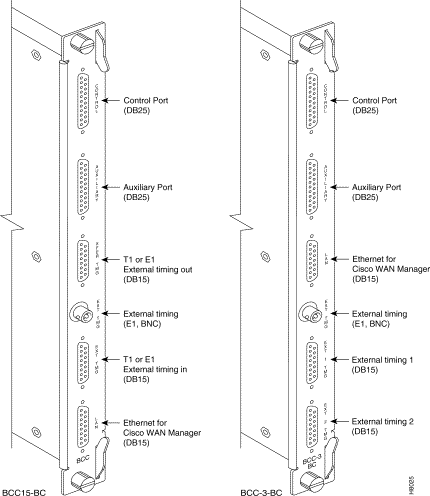
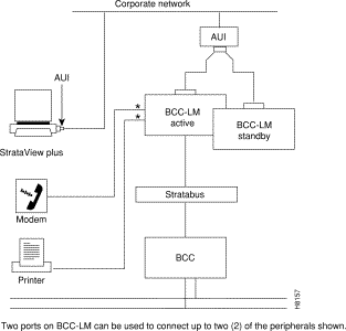
Another function of the line module back card is to provide two low-speed, serial communications ports. Refer to Table 2-5. The first port (CONTROL) is a bidirectional port used for connecting the BPX to a local terminal or to a modem for a remote terminal "dial-in" connection. The second port (AUXILIARY) is an output only and is used to connect to a log printer.
The SV+ NMS is connected to the LAN port on the BCC backcards. When control is provided via an Ethernet interface, the node IP address is configured with the cnflan command for the BPX node, and the back cards are Y-cable connected to an AUI adapter (individual cables and AUIs may also be used for each LAN port.) The LAN port of the primary Broadband Control Card is active. If the secondary Broadband Control Card becomes primary (active), then its LAN port becomes active. The SV+ workstation will automatically try to restore communications over the LAN and will interface with the newly active Broadband Controller Card.
For small networks, one SV+ workstation is adequate to collect statistics and provide network management. For larger networks, additional SV+ workstations may be required. Refer to the SV+ Operations Guide for more information.
The ASM card provides a number of support functions for the BPX including:
There are four significant circuits controlled by the ASM processor: alarm, power supply monitor, fan and temperature monitor, and card detection. The alarm monitor controls the operation of the front panel alarm LEDs and ACO and history pushbuttons as well as the alarm relays which provide dry contact closures for alarm outputs to customer connections. BPX system software commands the ASM card to activate the major and minor alarm indicators and relays.
The power supply monitor circuit monitors the status of the -48V input to the shelf on each of the two power buses, A and B. The status of both the A bus and B power bus is displayed on the ASM front panel.
The front panel displays the status of the node, and any major or minor alarms that may be present. Figure 2-18 illustrates the front panel of the ASM card and each front panel feature is described in Table 2-6.
| No. | Controls/ Indicator | Function |
|---|---|---|
1. | alarms LEDs | A red major alarm and a yellow minor alarm indicator to display the status of the local node. In general, a major alarm is service-affecting whereas a minor alarm is a non-service affecting failure. |
2. | dc LEDs | Two green LEDs displaying the status of the two dc power busses on the Stratabus backplane. On-indicates voltage within tolerance. Off-indicates an out-of-tolerance voltage. |
3. | ACO/hist LEDs | ACO LED (yellow) lights when the front panel ACO pushbutton is operated. History LED (green) indicates an alarm has been detected by the ASM at some time in the past but may or may not be clear at present time. |
4. | ACO switch | When operated, releases the audible alarm relay. |
5. | history clear switch | Extinguishes the history LED if the alarm condition has cleared. If alarm still present, history LED stays lighted. |
6. | card status LEDs | Active (green) indicates card is on-line and clear of alarms. Standby (yellow) indicates card is off-line. Fault (red) indicates a card failure is detected by the card self-test diagnostics. |
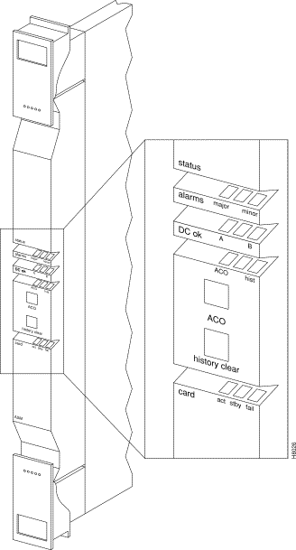
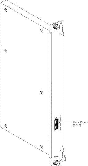
Figure 2-19 illustrates the face plate of the LM-ASM which contains a single subminiature connector (Table 2-7). The Alarm Relay connector provides dry-closure (no voltage) relay contact outputs.
| No. | Connector/ Indicator | Function |
|---|---|---|
1. | ALARM RELAYS | A DB15 connector for alarm relay outputs. Refer to Chapter 3 or Appendix C for pinouts. |
All BPX modules are interconnected by the BPX StrataBus backplane physically located between the front card slots and the back card slots. Even though the ATM data paths to/from the switching fabric and the interface modules are individual data connections, there are also a number of system bus paths used for controlling the operation of the BPX node. The StrataBus backplane, in addition to the 15 card connectors, contains the following signal paths:
All StrataBus wiring is completely duplicated and the two sets of bus wiring operate independently to provide complete redundancy. Either the A side wiring or B side wiring is enabled at any particular time by signals on the Control bus.
The BPX Network Interface group includes the Broadband Network Interface Cards (BNI) and associated Line Module cards. This card group provides the interface between the BPX and the ATM network (Figure 2-20). Different card sets operate at broadband data rates of DS3, E3, and at OC3/STM-1 rates.

The BNI-T3 and BNI-E3 interface the BPX with ATM T3 and E3 broadband trunks, respectively. These ATM trunks may connect to either another BPX, an IPX equipped with an AIT card, or an AXIS Shelf.
The BNI-3T3 back card provides three DS3 interfaces on one card while the BNI-E3 back card provides three E3 interface ports. The BNI back card types are very similar differing only in the electrical interface and framing. Any of the 12 general purpose slots can be used to hold these cards. Each BNI operates as a pair with a corresponding Line Module back card.
A summary of features for the BNI cards include:
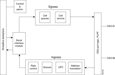
The BNI T3 and E3 cards are functionally alike except for the two different electrical interfaces. Refer to Figure 2-21 illustrating the main functional blocks in the BNI-3T3 card.
The DS3 port interface on the BNI-T3 card is the DS3 Function Block, a Physical Layer Protocol Processor (PLPP) custom semiconductor device, which implements the functions required by the DS3 PLCP as defined in various AT&T(TM) technical advisories. This VLSI device operates as a complete DS3 transmitter/receiver. Each BNI-3T3 has three of these devices, one for each of the DS3 ports on the card.
Egress
In the transmit direction (from the BPX switching matrix towards the transmission facility, referred to as egress), the BNI performs the following functions:
In the receive direction (from the transmission facility towards the BPX switching matrix, sometimes referred to as ingress), the BNI performs the following functions:

Some of the functions performed by the PLPP in the BNI-3T3 include:
In the BNI-3E3 the PLPP is replaced by a G.804 framer. The E3 framer obtains end-to-end synchronization on the Frame Alignment bytes. And a E3 transmitter/receiver replaces the DS3 transmitter/receiver for the BNI-3E3.
Another major BNI function is queuing of the ATM cells waiting to be transmitted to the network trunk. This is controlled by the Queue Service Engine. There are 32 queues for each of the three ports to support 32 classes of service, each with its programmable parameters such as minimum bandwidth, maximum bandwidth, and priority. Queue depth is constantly monitored to provide congestion notification (EFCN) status. The Queue Service Engine also implements a discard mechanism for the cells tagged with Cell Loss Priority.
The destination of each cell is contained in the Virtual Path Identifier/Virtual Circuit Identifier VPI/VCI) field of the cell header. This is translated to a Logical Connection Number via table lookup in the Network Address Table. Both terminating and through connections can coexist on a port.
A Serial Interface Module (SIM) provides cell interface to the StrataBus backplane. This operates at 800 Mbps. It provides a serial-to-parallel conversion of the data and loopback and pseudo-random bit generation for test purposes.
The transmit bandwidth can be throttled down for certain applications. For example, when interfacing with an IPX E3 ATM Trunk Card, the trunk transmit rate is limited to 40,000 cells/second. If a T2 trunk adapter is used, the trunk transmit rate is limited to 14,000 cells/second.
There are two types of self-tests that may be performed. A non-disruptive self test is automatically performed on a routine basis. A more complete, disruptive test may be initiated manually when a card failure is suspected. If the card self-test detects a failure, the card status LEDs displays an indication of the failure type (see Table 2-12).
Several loopback paths are provided. A digital card loopback path, used by the node for self-test, loops the data at the serial DS3 or E3 interface back towards the node. A digital line loopback loops the data at the electrical transmitter/receiver at the card output. Internally, the PLPP circuit in the BNI-T3 has several loopbacks for use by diagnostic routines.
There are several loopback paths within the BNI for testing. A digital loopback at the DS3 or E3 transmitter/receiver to check both the transmit and receive signal paths in the near-end BNI card. These loopbacks loop the signal in both directions, towards the StrataBus as well as towards the output. Therefore, they can be used to support both near end and far end maintenance loopback testing. On the BNI-3T3, there is a digital loopback capability to the PLPP processor used for the internal self test to basically check the operation of the signal processor.
Once a trunk has been assigned to a BNI card but before it is made active (upped), it is put in a loopback mode and a diagnostic test is continuously performed. This loopback is disruptive so it cannot be performed on a card that has an active trunk. This diagnostic test checks the data path through the BNI out to the BCC, through the switch matrix, and back to the BNI. Active trunks are constantly checked by the Communications Fail test routine which is part of system software.
The lower section of the BNI front panel (Figure 2-22) has a three-section, multicolored LED to indicate the card status. The card status LED is color-coded as indicated in Table 2-8. At the upper portion of the front panel, there is a three-section multicolored LED to indicate the status of the three ports on the BNI. Types of failures are indicated by various combinations of the card status indicators as indicated in Table 2-12.
| Status | LED color | Status Description |
|---|---|---|
Port | off | Trunk is inactive and not carrying data. |
| green | Trunk is actively carrying data. |
| yellow | Trunk is in remote alarm. |
| red | Trunk is in local alarm. |
Card | green (act) | Card is on-line and one or more trunks on the card have been upped. If off, card may be operational but is not carrying traffic. |
| yellow (stby) | Card is off-line and in standby mode (for redundant card pairs). May not have any upped trunks. If blinking, indicates card firmware or configuration data is being updated. |
| red (fail) | Card failure; card has failed self-test and/or is in a reset mode. See Table 2-12 for more information. |

| act | stby | fail | Failure Description |
|---|---|---|---|
on | off | on | Non-fatal error detected; card is still active. |
off | on | on | Non-fatal error detected; card is in standby mode. |
off | blinking | on | Fatal error detected; card is in a reboot mode. |
on | on | on | Card failed boot load and operation is halted. |
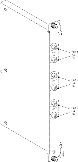
The Line Modules for the BNI-T3 and BNI-E3 front cards are back cards used to provide a physical interface to the transmission facility. The LM-3T3 is used with the BNI-T3 and the LM-3E3 with the BNI-3E3. The Line Module connects to the BNI through the StrataBus midplane. Two adjacent cards of the same type can be made redundant by using a Y-cable at the port connectors. All three ports on a card must be configured the same.
Refer to Figure 2-23, Figure 2-24, and Table 2-10 which describe the faceplate connectors of the LM-3T3 and LM-3E3. There are no controls or indicators.
The LM-3T3 provides the following features:
A final node loopback is found at the end of the LM-3T3 or LM-3E3 card. This is a metallic loopback path that uses a relay contact closure. It is a near-end loopback path only; the signal is looped at the final output stage back to circuits in the node receive side. It is only operated when the corresponding front card is in standby.
| No. | Connector | Function |
|---|---|---|
1. | PORT 1 RX - TX | BNC connectors for the transmit and receive T3/E3 signal to/from ATM trunk #1. |
2. | PORT 2 RX - TX | BNC connectors for the transmit and receive T3/E3 signal to/from ATM trunk #2. |
3. | PORT 3 RX - TX | BNC connectors for the transmit and receive T3/E3 signal to/from ATM trunk #3. |

The BNI-155 interfaces the BPX with ATM OC3/STM-1 broadband trunks. The ATM trunk may connect to either another BPX or customer CPE equipped with an ATM OC3/STM-1 interface.
Currently there are three BNI-155 back cards, the LM-2OC3-SMF for single-mode fiber intermediate range, the LM-2OC3-SMFLR for single-mode fiber long range, and the LM-2OC3-MMF for multi-mode fiber. Any of the 12 general purpose slots can be used to hold these cards. These backcards may also be used with the ASI-155.
A summary of features for the BNI-155 cards include:
Egress
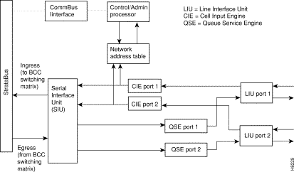
In the transmit direction (from the BPX switching matrix towards the transmission facility, referred to as egress), the BNI performs the following functions (Figure 2-25):
Ingress
In the receive direction (from the transmission facility towards the BPX switching matrix, referred to as ingress), the BNI performs the following functions (Figure 2-25):
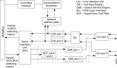
In the egress direction, the BNI-155 has 2 Queue Service Engine (QSEs) which provide each of the ports with 12 programmable queues with selectable parameters such as minimum bandwidth, priority, and maximum bandwidth. The BNI queues are based on a class of service algorithm. The BNI supports the following trunk queues:
In the ingress direction, the BNI-155 has 2 Cell Input Engines (CIEs) that convert the incoming cell headers to the appropriate connection ID based on input from a Network Address Table.
The Serial Interface Unit (SIU) provides the BNI with an 800 Mbps cell interface to the StrataBus. It provides serial-to-parallel conversion of data, along with loopback and test signal generation capabilities.
The Line Interface Unit (LIU)performs the following ingress functions:
The Line Interface Unit (LIU) performs the following egress functions:
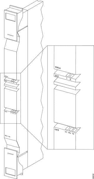
The BNI-155 front panel (Figure 2-26) has a three-section, multicolored "card" LED to indicate the card status. The card status LED is color-coded as indicated in Table 2-11. A three-section multicolored "port" LED indicates the status of the two ports on the BNI-155. Types of failures are indicated by various combinations of the card status indicators as indicated in Table 2-12.
| Status | LED color | Status Description |
|---|---|---|
port | off | Trunk is inactive and not carrying data. |
| green | Trunk is actively carrying data. |
| yellow | Trunk is in remote alarm. |
| red | Trunk is in local alarm. |
card | green (act) | Card is on-line and one or more trunks on the card have been upped. If off, card may be operational but is not carrying traffic. |
| yellow (stby) | Card is off-line and in standby mode (for redundant card pairs). May not have any upped trunks. If blinking, indicates card firmware or configuration data is being updated. |
| red (fail) | Card failure; card has failed self-test and/or is in a reset mode. See Table 2-12 for more information. |
| act | stby | fail | Failure Description |
|---|---|---|---|
on | off | on | Non-fatal error detected; card is still active. |
off | on | on | Non-fatal error detected; card is in standby mode. |
off | blinking | on | Fatal error detected; card is in a reboot mode. |
on | on | on | Card failed boot load and operation is halted. |
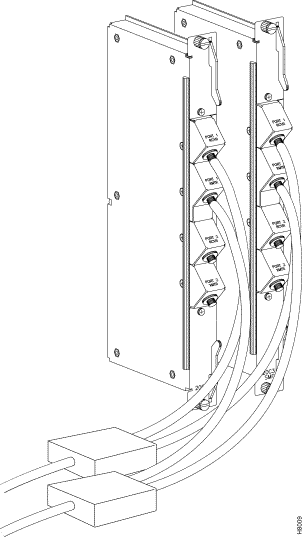
The Line Modules for the OC3 BNI cards are back cards used to provide a physical interface to the transmission facility. There are three types, a single-mode fiber intermediate range, single-mode fiber long range, and a multi-mode fiber backcard. The Line Modules connect to the BNI through the StrataBus midplane.
For connector information, refer to Figure 2-27 and Table 2-13 for the LM-OC3-SMF and to Figure 2-28 and Table 2-14 for the LM-OC3-MMF. The LM-OC3-SMFLR uses the same type of connectors as the LM-OC3-SMF.
| No. | Connector | Function |
|---|---|---|
1. | PORT | FC-PC connectors for the transmit and receive OC3 signal to/from ATM trunk #1. |
2. | PORT | FC-PC connectors for the transmit and receive OC3 signal to/from ATM trunk #2. |
| No. | Connector | Function |
|---|---|---|
1. | PORT | Duplex SC connectors for the transmit and receive OC3 signal to/from ATM trunk #1. |
2. | PORT | Duplex SC connectors for the transmit and receive OC3 signal to/from ATM trunk #2. |


The LM-OC3-SMF (Model SMF-2-BC) backcards may be Y-cabled for redundancy using the Y-Cable splitter shown in Figure 2-29. The cards must be configured for Y-Cable redundancy using the addyred command.
The BPX Service Interface group includes the ATM Service Interface (ASI) card and an associated Line Module card (Figure 2-30). This card group provides a direct interface between an ATM user device such as the AXIS and an ATM network.
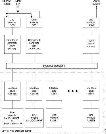
The ATM Service Interface Card for T3 and E3 interfaces (ASI-1) is a front card for use in the BPX to interface an ATM user device e.g., CPE (Customer Premise Equipment). The ASI provides an industry-standard ATM User-to-Network Interface (UNI) or ATM Network-to-Network Interface (NNI) to the BPX switching fabric.
A summary of features for the ASI card include:
Each ASI-1 card provides two ATM UNI/NNI ports, each operating at DS3 rates or E3 rates (Figure 2-31). Any of the 12 general purpose slots can be used to hold these cards. The ASI-1 operates with a corresponding T3 or E3 Line Module back card LM-2T3 or LM-2E3, respectively. Only the first two connectors on the back card are active; the lower port is not used.
Each port provides an aggregate ATM connection bandwidth of 96,000 cells/second (T3) or 80,000 cells/sec (E3), or 353,208 cells/sec (OC3).
Connections are added using the addcon command.
Some of the functions performed by the PLPP in the ASI-1 include:
Connections are routed using the VPI and VCI address fields in the UNI header. The allowable range for VPI is from 0 to 255 (UNI) and 0 to 1023 (NNI), while VCI can range from 1 to 65535. A total of 1000 combinations of these can be used per ASI card at any one time.
A total of 1000 logical connections (ungrouped) may be configured for the node at any one time. On the BPX, 5000 grouped connections can be configured. The ASI-1 supports 1000 connections per card.
Two connection addressing modes are supported. The user may enter a unique VPI/VCI address in which case the BPX functions as a virtual circuit switch. Or the user may enter only a VPI address in which case all circuits are switched to the same destination port and the BPX functions as a virtual path switch in this case.
There are sixteen egress queues per line (port), including CBR, VBR, and ABR. When a connection is added, the user selects either constant bit rate (CBR), variable bit rate (VBR), or available bit rate (ABR, which uses ForeSight). The CBR queue has higher priority. Queue depth is specified when configuring a line. Maximum depth that can be specified for any one queue is 11,000 cells. Total queue depth cannot exceed 22,000 cells.
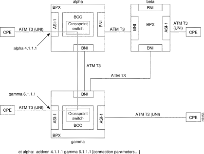
Connections are routed between CPE connected to ASI ports (Figure 2-32). Before adding connections, an ASI line is upped with the upln command and configured with the cnfln command. Then the associated port is configured with the cnfport command and upped with the upport command. Following this, the ATM connections are added via the addcon command with the syntax: slot.port.vpi.vci. The example shows a connection between alpha 4.1.1.1 and gamma 6.1.1.1.
The slot number is the ASI card slot on the BPX. The port number is one of two ports on the ASI, the VPI is the virtual path identifier, and the VCI is the virtual circuit identifier. (The top two ports on the LM-2T3 card are used, the bottom one is not.)
The VPI and VCI fields have significance only to the local BPX, and are translated by tables in the BPX to route the connection. Connections are automatically routed by the AutoRoute feature once the connection endpoints are specified.
Connections can be either Virtual Path Connections (VPC) or Virtual Circuit Connections (VCC). Virtual Path Connections are identified by an * in the VCI field. Virtual Circuit Connections specify both the VPI and VCI fields. Refer to the Command Reference and System Manual for further information.
Port, line, and channel statistics are collected by the ASI-1. Refer to the StrataView Plus Operations Guide for a listing and description of these statistics.
The ASI front panel (Figure 2-33) has a three-section, multicolored "card" LED to indicate the card status. The card status LED is color-coded as indicated in Table 2-15. A two-section multicolored "port" LED indicates the status of the two ports on the ASI. The port status LED display is color-coded as indicated in Table 2-15
| Status | LED color | Status Description |
|---|---|---|
port | off | Line is inactive and not carrying data. |
| green | Line is actively carrying data. |
| yellow | Line is in remote alarm. |
| red | Line is in local alarm. |
card | green (act) | Card is on-line and one or more ports on the card have been upped. If off, card may be operational but is not carrying traffic. |
| yellow (stby) | Card is off-line and in standby mode (for redundant card pairs). May not have any upped ports. If blinking, indicates card firmware or configuration data is being updated. |
| red (fail) | Reserved for card failure. |

The T3 Line Module for the ASI-1 Front Card is a backcard used to provide a physical interface to the service interface (Figure 2-34). The Line Module connects to the ASI-1 through the StrataBus midplane. Two adjacent cards of the same type can be made redundant by using a Y-cable at the port connectors.
Except for using two ports instead of three, the LM-2T3 back card operates similarly to the BNI back cards, described previously.

The E3 Line Module for the ASI-1 Front Card is a backcard used to provide a physical interface to the service interface (Figure 2-35). The Line Module connects to the ASI-1 through the StrataBus midplane. Two adjacent cards of the same type can be made redundant by using a Y-cable at the port connectors.
Except for using two ports instead of three, the LM-2E3 back card operates similarly to the BNI back cards, described previously.

The ATM Service Interface Card for OC3/STM-1, the ASI-155, is a BPX front card used to interface with an ATM user device e.g., CPE (Customer Premise Equipment). The ASI provides an industry-standard ATM User-to-Network Interface (UNI) or ATM Network-to-Network Interface (NNI) over OC3 lines to the BPX switching fabric.
Currently there are three ASI-155 back cards, the LM-2OC3-SMF for single-mode fiber intermediate range, the LM-2OC3-SMFLR for single-mode fiber long range, and the LM-2OC3-MMF for multi-mode fiber. Any of the 12 general purpose slots can be used to hold these cards. These backcards may also be used with the BNI-155
A summary of features for the ASI-155 card include:
Connections are routed using the VPI and VCI address fields in the UNI header. The allowable range for VPI is from 0 to 255 (UNI) and 0 to 1023 (NNI), while VCI can range from 1 to 65535. A total of 1000 combinations of these can be used per ASI card at any one time. Future releases will support the full ATM address range.
There are two connection addressing modes supported. The user may enter a unique VPI/VCI address in which case the BPX functions as a virtual circuit switch. Or the user may enter only a VPI address in which case all circuits are switched to the same destination port and the BPX functions as a virtual path switch in this case.
There are 12 egress queues per line (port), two of which are used. These are for CBR, and VBR. When a connection is added, the user selects either a constant bit rate (CBR) or variable bit rate (VBR) connection class.
Connections are routed between CPE connected to ASI ports. Before adding connections, an ASI line is upped with the upln command and configured with the cnfln command. Then the associated port is configured with the cnfport command and upped with the upport command. Following this, the ATM connections are added via the addcon command with the syntax: slot.port.vpi.vci.
The slot number is the ASI card slot on the BPX. The port number is one of two ports on the ASI, the VPI is the virtual path identifier, and the VCI is the virtual circuit identifier.
The VPI and VCI fields have significance only to the local BPX, and are translated by tables in the BPX to route the connection. Connections are automatically routed by the AutoRoute feature once the connection endpoints are specified.
Connections can be either Virtual Path Connections (VPC) or Virtual Circuit Connections (VCC). Virtual Path Connections are identified by an * in the VCI field. Virtual Circuit Connections specify both the VPI and VCI fields.
ATM to Frame Relay Network and Service Interworking connections to the ASI are also supported. In the case of Network Interworking, the user CPE must be aware of the interworking function and provide the appropriate protocol mapping.
Refer to the Command Reference Manual and System Manual for further information.
For ingress traffic, the ATM Layer Interface (ALI) provides traffic management and admission controls (UPC) for the ASI-155 (Figure 2-36). The ASI-155 supports CBR and VBR connections and employs a single leaky bucket GCRA mechanism for policing cell streams seeking entrance to the network. Each PVC (VPC.VCC) is policed separately, providing firewalling between connections, and assuring that each connection uses only a fair share of network bandwidth. The ALI also performs ingress OAM functions.
The single leaky bucket policing function is implemented using a GCRA (Generic Rate Algorithm) defined by two parameters:
In the ingress direction, the ASI-155 has 2 Cell Input Engines (CIEs) that convert the incoming cell headers to the appropriate connection ID based on input from a Network Address Table.
For egress traffic, the Supervisory Cell Filter (SCF) provides routing and direction of non-data cells, such as test cells and OAM cells.
The Serial Interface Unit (SIU) provides the ASI with an 800 Mbps cell interface to the StrataBus. It provides serial-to-parallel conversion of data, along with loopback and test signal generation capabilities.
The Line Interface Unit (LIU) performs the following ingress functions:
The Line Interface Unit (LIU) performs the following egress functions:
Port, line, and channel statistics are collected by the ASI-155. The StrataView Plus workstation is used to collect and monitor these statistics. For additional information regarding ASI-155 statistics refer to the StrataView Plus Operations Guide.
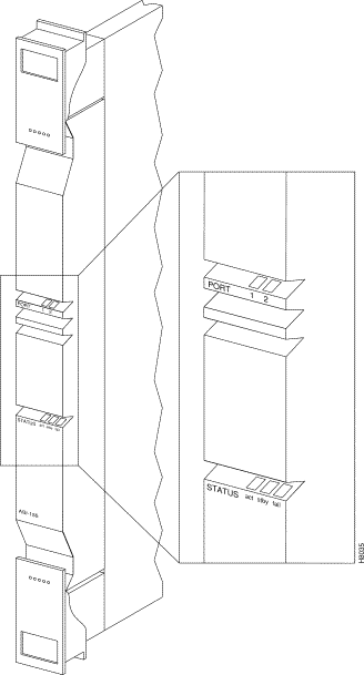
The ASI-155 front panel (Figure 2-37) has a three-section, multicolored "card" LED to indicate the card status. The card status LED is color-coded as indicated in Table 2-16. A two-section multicolored "port" LED indicates the status of the two ports on the ASI-155. The port status LED display is color-coded as indicated in Table 2-16.
| Status | LED color | Status Description |
|---|---|---|
port | off | Line is inactive and not carrying data. |
| green | Line is actively carrying data. |
| yellow | Line is in remote alarm. |
| red | Line is in local alarm. |
card | green (act) | Card is on-line and one or more ports on the card have been upped. If off, card may be operational but is not carrying traffic. |
| yellow (stby) | Card is off-line and in standby mode (for redundant card pairs). May not have any upped ports. If blinking, indicates card firmware or configuration data is being updated. |
| red (fail) | Reserved for card failure. |
The LM- 2OC3 -SMF (Model SMF-2-BC) line module for the ASI-155 Front Card is a backcard that provides a SMF intermediate range service interface (Figure 2-27). The line module connects to the ASI-155 through the StrataBus midplane. Two adjacent cards of the same type can be made redundant by using a Y-cable at the port connectors. This is the same LM-2OC3-SMF backcard that is used for the BNI-155.
The LM- 2OC3 -SMFLR (Model SMFLR-2-BC) line module for the ASI-155 Front Card is a backcard that provides a SMF long range service interface. The line module connects to the ASI-155 through the StrataBus midplane. This is the same LM-2OC3-SMFLR backcard that is used for the BNI-155.
The LM-2OC3 -MMF (Model MMF-2-BC) line module for the ASI-155 Front Card is a backcard that provides a MMF service interface (Figure 2-28). The line module connects to the ASI-155 through the StrataBus midplane. This is the same LM-2OC3-SMF backcard that is used for the BNI-155.
The LM-OC3-SMF (Model SMF-2-BC) backcards may be Y-cabled for redundancy using the Y-Cable splitter (Model SMFY) shown in Figure 2-29. The cards must be configured for Y-Cable redundancy using the addyred command.
At least one node in the network (or network domain if a structured network) must include a Strata-View Plus network management station (Figure 2-38). A Y-cable may used to connect the LAN ports on the primary and secondary BCC Line Modules, through an AUI to the LAN network, as only one BCC is active at a time. The serial Control port may be connected to a dial-in modem for remote service support or other dial-up network management access. The serial Auxiliary port is used for outgoing data only, for example, for connection to a printer.
![]()
![]()
![]()
![]()
![]()
![]()
![]()
![]()
Posted: Thu Jan 18 14:29:45 PST 2001
All contents are Copyright © 1992--2001 Cisco Systems, Inc. All rights reserved.
Important Notices and Privacy Statement.