|
|

This chapter is provided for users who wish to have an in-depth knowledge of network frame relay connections and related functions.
The examples in the "Introduction" through "Connection Parameters" sections of this chapter are based on IPX Frame Relay connections, but the general information is applicable to the IGX and to the AXIS shelf. See the respective Reference Manuals for Frame Relay information specific to the IGX and the AXIS shelves.
The use of the Port Concentrator Shelf (PCS) which extends the port capacity of an FRP on an IPX or of an FRM on an IGX from 4 high-speed ports to 44 low-speed ports is described in the "Port Concentrator Shelf Frame Relay Connections" section later in this chapter. The addition and configuration of frame relay connections via the ports on the PCS is essentially the same as that for connections added directly at an FRP port. The general information provided in the "Introduction" through "Connection Parameters" sections of this chapter is applicable to the PCS, except as described in the "Port Concentrator Shelf Frame Relay Connections" section.
Frame relay can be used to transport virtually any higher layer data protocol. Higher layer protocol frames are encapsulated in Frame Relay frames, usually according to the scheme defined by Internet Standards RFC-1294. Figure 10-1 illustrates this for a typical LAN format (TCP-IP).
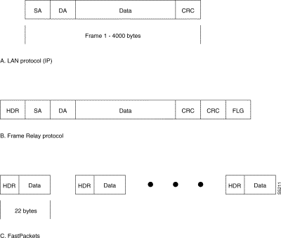
Frame relay surrounds the LAN data frame with its own protocol elements allowing it to carry LAN data transparently. The flags are used to identify the start and end of frame relay frames, which can be up to 4506 bytes long. Since each FastPacket contains only 20 bytes of data, a number of packets may be needed to transmit one frame relay frame (Items A and C in Figure 10-1). A StrataCom network recognizes three core frame relay elements:
The frame relay network destination address is given by the Data Link Connection Identifier (DLCI) located in the header of each frame relay data frame. A connection's DLCI is simply a number used to distinguish the connection from all the other connections that share the same physical port between the user equipment and the frame relay port. It is assigned by the network operator when the connection is added to the network. DLCI values range from 0 to1023 with 0 to15 and 1007 to 1023 reserved for special use.
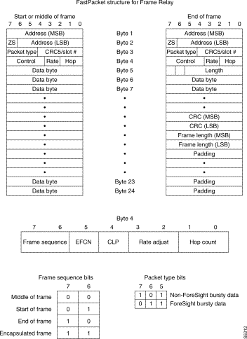
A frame length measurement is inserted at the end of the FastPacket carrying the last of the data for the frame. It is used to perform error detection on the whole frame relay frame. A ZBTSI algorithm is used to remove any bytes consisting of all zeros. The ZS bit indicates one or more data bytes were removed before being transmitted. One or more of the first data bytes acts as a pointer to the removed byte so it can be replaced at the receiving end.
At the receiving end, the IPX reassembles the packet data into a complete frame relay frame, checks for correct CRC and frame length, and outputs the frame to the destination device only if the frame relay CRC is correct. Frame relay ignores any CRC that may be associated with the LAN protocol.
Since the frame relay dataframe may be up to 4096 bytes long, it will likely require a number of FastPackets to transmit all of the frame relay data. The FRP card at the far end node will wait until the whole frame relay data frame has been received and checked before it will begin to output it to the far end user device.
All FastPackets for a frame relay connection travel along the same network route; they cannot get out of sequence as can be the case for other packet networks. But the frame relay packets are not necessarily contiguous over a packet line as there are other packet types that are being transmitted at the same time. The IPX inserts start of frame and end of frame codes into the frame relay message packet to assist the far end node in preserving the proper sequence of packets (Figure 10-2). An encapsulated frame code indicates the packet message frame contains a complete frame relay data frame.
The hop count is incremented at each intermediate node to indicate how many hops in the network the packet has traveled. It is used at intermediate nodes to give higher priority in various packet line queues to frame relay data that has traveled over more hops (with associated longer delays) to attempt to even out the delay for various frame relay circuits.
The packet frame carrying the last frame relay frame (Figure 10-2) has a format different from all the rest. As it is unlikely that the last frame will be completely filled, the remaining bytes are used to carry a 2-byte CRC for error checking on the complete frame relay frame. The next two bytes indicate the length of the frame relay frame as a check against a dropped packet in case the CRC is still good. Any remaining packet message bytes are filled with padding (hex 7E). If the CRC check at the receiving end detects an error in the frame relay frame, the whole frame relay frame is discarded.
At the transmitting node, the frame relay Data Link Connection Identifier (DLCI) is replaced by the IPX packet header routing address for the destination node. At the destination node, the FRP card replaces this routing address with the source DCLI code before transmitting it to the user.
The maximum number of frame relay connections possible in a node is 1024. This is accomplished by bundling frame relay connections into groups. All bundled frame relay circuits have the same destination and are routed over the same route. Frame relay circuits originating at different FRPs in the same node may be bundled into the same group
An example of frame relay addressing is presented in Figure 10-3. It illustrates a simple three-node network with a single router at nodes alpha and beta (R1 and R2) connected to the first of four ports of an FRI card, and two routers (R3 and R4) connected to ports 1 and 2 of a FRI at node gamma.
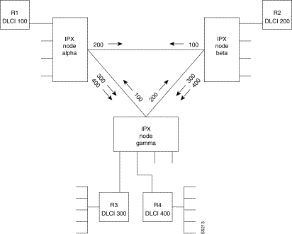
A Port ID can be assigned to each IPX frame relay port using the configure FR port command. As an option, the Port ID can be used as a starting point for assigning DLCI's. The frame relay connection between alpha and beta has been added with a DLCI of 100 at alpha and 200 at beta. Likewise, the connection between nodes alpha and gamma have been assigned a DLCI of 300 for router R3 and 400 for router R4.
When router 1 at alpha wants to send a frame to router 2 at beta, it inserts the DLCI 200 in the frame relay header. If it wants to send a frame to router 4 at gamma, it inserts 400 in the DLCI field. Each router will have a list of all available destinations (routers) connected to the network and their corresponding DLCI number.
In this example, each router in the network has a different DLCI. A circuit from anywhere in the network to router 2, for example, will use a DLCI of 200 to identify the destination as node beta, router R2. This makes it easy for anyone in the network to associate destination locations with a simple numbering scheme. When a frame is broadcast to multiple destinations, there will be no confusion as each destination address is unique.
This addressing scheme is often called Global Addressing. Global Addressing uses the DLCIs to identify a specific end device, which makes the frame relay network look more like a LAN. Figure 10-4 illustrates a network using global addressing.
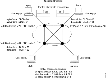
Another user community that is not connected with the first could have its own global addressing scheme using some, or all, of the same DLCIs. This might be the case when a public network provider has a number of customers, each with their own frame relay network, running on the same IPX hardware.
Since the DLCIs have only "local significance" the only real restriction on the use of DLCIs is that they are not used for more than one destination from the same port. This is not to say that the same DLCI numbers could not be reused at another port at the same or another IPX node. And, indeed, another addressing scheme might assign the same DLCI to both ends of each virtual circuit between nodes.
For example, router R2 at beta could have a DLCI of 100 and 100 could also be used as the DLCI for router R1 at alpha. Now, a frame originating at either alpha or beta would use 100 as its destination address and the same PVC to transmit the frame. But this addressing scheme can be confusing for the same number refers to two different destinations. This type of addressing convention is sometimes called connection addressing since the address is only unique at the local port. Another addressing scheme, Local Addressing, reuses DLCIs at each node and only at that node are they unique.
Figure 10-5 illustrates a block diagram of a simple three-node network and the buffers encountered by the frame relay data. Frames are assembled by the router and are transmitted to the FRP port at the Port Rate determined by the hardware. The frame header contains the DLCI from the User Device.
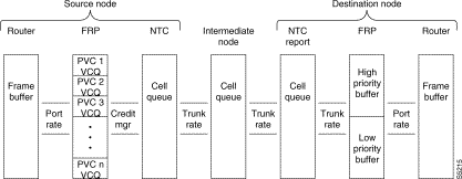
This DLCI, along with the port number, is used to determine a unique permanent virtual connection within the IPX network. Each PVC has its own individual queue, VC Q, at the input to the FRP. Each VC Q is user specified and can be up to 65 Kbytes deep. A FRP card can have up to 252 PVCs associated with it.
The FRP uses this DLCI in a lookup table to find a FastPacket address for routing through the network. This address is placed in the header of one or more IPX packets into which the frame is loaded and the packets are forwarded to the appropriate trunk card where they are queued in a frame relay Cell Queue for transmission out to the network. There are separate cell queues for ForeSight and non-ForeSight traffic. The IPX Credit Manager determines the rate at which the frames are unloaded from the cell queue and applied to the network.
The packets are then routed across the IPX network. At each intermediate node, the packets containing frame relay data are queued in their Cell Queues for transmission over the next hop. Packets containing frame relay data share the same network facilities as packets containing voice, low-speed data, synchronous data, PCC, and video traffic.
At the receiving end FRP, packets containing frame relay data are loaded into one of two Port Buffers. The original frame is reconstructed from the packets and then the source DLCI is replaced with the destination DLCI. This identifies the source of the data.
One of the two buffers is for connections marked as high priority, the other is for normal frame relay data. Data in the high priority queue is transmitted to the destination router first. One final stage of buffering is found in the router as it receives data from the FRP in bursts.
Each FRP VC Q buffer can be allocated from 1 to 65 Kbytes. The larger buffer sizes increase the overall connection delay but larger buffers also minimize the possibility of buffer overflow. Buffer space that is not used by frame relay connections can be allocated to other types of connections.
There are four types of frame relay connections available with the IPX:
The IPX provides permanent virtual circuits (PVC) for interconnecting user data devices (routers, bridges, and packet switches). The PVCs are created internally in the IPX, using routing tables and FastPacket switching. The user device is connected to the Frame Relay Interface (FRI) card set installed in the IPX, which provides the adaptation layer function to convert between the frame relay format and the IPX FastPacket format (Figure 10-6).
In IPX networks, all packets belonging to a particular PVC travel along the same route. This means all packets carrying the frame relay data for a particular destination are by definition transmitted in sequence and experience approximately the same delay, unlike previous low-speed packet networks. IPX frame relay packets may travel over multiple network hops (10 maximum) to reach their destination.
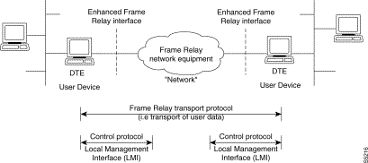
The data transfer protocol used by frame relay is very simple. The user device transmits data frames, based upon the core functions of Q.922 (LAPD), to the frame relay network. The frame relay network looks at the first two octets of the frame Data Link Connection Identifier (DLCI) and proceeds to forward the frame to the destination user device.
The only processing performed by the IPX on the frame is bit insertion and verification and a Frame Check Sequence (FCS) for error checking. Termination of the data link is not performed. The destination DLCI is replaced with a DLCI that identifies the source of the data frame.
Because so little processing is performed, the frame relay service can offer much higher speed interconnection between user devices than can be achieved with conventional packet switches that relay layer 3 protocol data units. Refer to ITU-T and ANSI Standards for further definitions on data transfer protocol and procedures.
Grouping of frame relay connections is a means of increasing the capacity of the IPX node to handle frame relay circuits. Without grouping connections, each node is capable of routing a maximum of 255 routing entities. If each routing entity were a frame relay permanent virtual circuit, a node would almost reach its capacity with one FRP card, which can handle up to 252 PVCs. By grouping frame relay circuits, a node can handle up to 1024 frame relay connections.
Grouped connections group together up to 16 permanent virtual circuits having the same routing characteristics. Each connection group then is treated as one connection as far as routing is concerned but in actuality, is a group of 16 virtual circuits. The individual circuits do not have to all be added at the same time, they do not necessarily have to be in any numeric sequence, and they can be located on any FRP in any IPX slot in the node. The only restrictions are that each circuit in the group must be added at the same node, follow the same network routing path, and terminate on the same far end node.
Up to 255 connection groups to be defined for each node. This would indicate that the node capacity was 4000 connections (255 groups x 16 connections per group). However, other considerations currently limit the actual total connections per node to 1024.
Individual connections may be added to, or deleted from, an existing connection group at any time. Each individual circuit in a group retains all of its own non-routing related characteristics, for example failure alarms, maintenance loop, and circuit configuration. Only the routing parameters (route, restriction, routing state, COS, and ownership) are identical for all circuits in a connection group.
Each frame relay circuit first must be added to the node using the Add Connection (addcon) command. Then the connection group must be defined using an Add Connection Group (addcongrp) command. Then added to the group with the Group Connection (grpcon) command. Each circuit in the group must have the same originating node and destination node.
All the PVCs in a group are routed and rerouted as a single entity. They follow the same network path and are failed and repaired together. The cumulative bandwidth requirements of all connections in the group are used when searching for a route. These routes are not assigned any higher priority for rerouting during network failure. But, because it is expected that connection groups will have a large accumulated bandwidth, since they will contain multiple virtual circuits, they will be routed ahead of smaller connections.
Bundled frame relay connections, sometimes referred to as "mesh bundling", are similar in concept to grouped connections but are somewhat more restrictive. Bundled connections simplify the specification of large numbers of FR connections (up to 1000 circuits per node). This feature is used to connect a set of consecutively numbered frame relay ports together.
As with grouped connections, a bundled connection can consist of up to 16 virtual circuits with the same routing and same destination node. However, all circuits in a bundled connection must be located on the same FRP card. They do not necessarily have to originate and terminate on the same port at each end but the ports must be on the same card. For example, each of the four ports can have four connections per port.
An example of a mesh bundled connection is illustrated in Figure 10-7 as follows. Suppose we have two ports at the local node (node alpha) that we want to connect to three ports at the remote node (node beta). This will result in six PVCs (2 X 3) fully interconnecting the five ports. The Add Connection (addcon) command does not need to individually specify each connection, only the ports.
This will result in six connections as follows:
alpha 1 to beta 1 | and | alpha 2 to beta 1 |
alpha 1 to beta 2 | and | alpha 2 to beta 2 |
alpha 1 to beta 3 | and | alpha 2 to beta 3 |
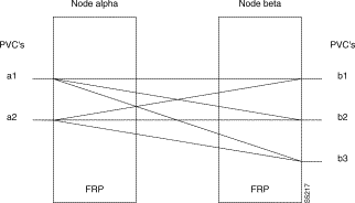
Unlike grouped connections, the circuits in a bundled connection must all be added at the same time and use the port ID of each FRP port for the destination address as the DLCI. The Add Connection (addcon) command for bundled connections uses only the slot and port number for specifying and consecutively numbers the PVCs, starting with the port number, for the first port to make it simple to add bundled connections.
Frame forwarding supports a data connection like that described for the SDP or LDP. It uses the capabilities of the frame relay card to provide bursty data, DFM-like data compression for high speed data connections. Frame forwarding is configured on an individual FRP port basis.
This feature is used to interconnect various data applications that do not conform to the frame relay Interface Specification, such as bridges, switches, front end processors, and other equipment, supporting SDLC, HDLC, or LAP-B interfaces.
1. Frame length must be between 5 to 4506 bytes.
2. Valid ITU-T CRC/FCS required.
3. Flags must be 7E hex.
In this configuration all frames received on a local FRP port are transmitted via a single PVC to a remote FRP port, and all frames received on a remote FRP port are transmitted via a single PVC to a local FRP port. Refer to the discussion of frame relay in Chapter 2 for port hardware interface description and operating bit rates. Note that a frame forwarding connection is still a frame-oriented interface, as in the case of normal frame relay connections.
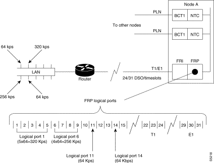
The Frame Relay T1/E1 application allows the user to group FRP DS0/timeslots into "logical ports". These logical ports may be a single DS0/timeslot or groups of contiguous DS0 timeslots. Logical ports that consist of multiple DS0/timeslots are at the full rate of 64 Kbps per timeslot. Frame Relay LMI is simultaneously supported on a maximum of 31 T1/E1 logical ports.
Logical ports that consist of single DS0 timeslots may be configured in 56 Kbps or 64 Kbps. If configured for 56 Kbps the IPX will strip off the signalling bit in the incoming octet and stuff a "1" in the outgoing octet. This 56 Kbps rate is typically used for groomed DDS circuits that appear on a T1/E1 line. Figure 10-8 is a simplified illustration of multiple and single DS0/timeslots comprising logical ports.
Logical ports are created with the Add Frame Relay Port (addfrport) command, which associates a line number (circuit line) and DS0/timeslots to form a logical port. The lowest timeslot number of the created group becomes the logical port number. The created logical port number is used to up the port, add connections, and display statistics. Logical ports are deleted using the Delete Frame Relay Port (delfrport) command, which ungroups any multiple DS0/timeslots and/or unassign a single DS0/timeslot logical port.
There are two types of network interfaces possible at frame relay ports, a User-to-Network Interface (UNI) and a Network-to-Network Interface (NNI). The User-to-Network Interface is defined as the port where a user device, such as a router, interfaces with a StrataCom wide area network carrying the frame relay traffic. However, the functions performed by each network interface is quite different as will be discussed in the following paragraphs.
A Network-to-Network Interface is a port that forms a boundary between two independent wide area networks, e.g. a StrataCom network and another network and may or may not consist of StrataCom equipment. There is no user device connected, only another network port. Each network interface in a StrataCom network consists of a port on a FRP card.
The User-to-Network Interface for frame relay permanent virtual circuits (PVC) is a defined set of protocols and procedures. Currently, the IPX supports UNI via the following protocols: StrataCom LMI, ITU-T Q.933 Annex A, and ANSI T1.617 Annex D. Each of the three protocols is quite similar and only the StrataCom Local Management Interface (LMI) will be discussed here.
LMI transmits on a logical connection between the IPX and the user device separate from the data path and uses DLCI 1023 (Figure 10-9). This connection is a special PVC, carrying messages between the IPX frame relay port and the user device. The messages transmitted via the LMI protocol provide the following information to the user device:
Some user devices can obtain the network configuration dynamically using LMI messages. With these devices, the Network Administrator assigns Data Link Connection Identifiers (DLCIs) for both ends of each connection in the network and the user device interrogates the frame relay port to determine the DLCI assignment. If the user device does not have this feature, then the Network Administrator must manually configure the user device to use the DLCIs programmed into the IPX network.
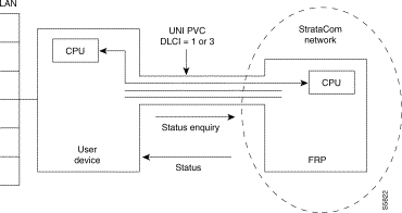
Frame Relay networks utilizing StrataCom nodes can be seamlessly connected together and to other frame relay networks adhering to standards set forth by the Frame Relay Forum. Internetwork connections; originate within one network and terminate inside another independent network. For example, a circuit might originate within a private network, pass through a public switched network, and terminate within a third, private network.
Within a StrataCom flat network, the status of every frame relay PVC is known by every node in the network since it is distributed network-wide by system software communicating with each node. There are three possible status to report:
This is illustrated in Figure 10-10 with a multi-network PVC connecting a user at the West end of the connection (User-W) connecting to a StrataCom network and a user at the East end (User-E) to an adjacent, independent, network. This connection is segmented with that portion of the connection traversing one of the networks called a PVC segment.
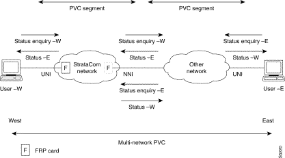
At the boundary of the two networks are two nodes, one in each network, with one or more frame relay NNI ports in one node connecting to a like number of ports in the node in the other network. These ports carry the internode connection. Each of the NNI ports constantly monitors the connection interface between the two networks. Each of the frame relay ports will periodically poll the corresponding port in the other network using a Status Enquiry message (heartbeat). The interval of this polling is configurable, set by the Link Integrity Timer (T391), and normally polls every six seconds.
This same port expects to receive a Status message back from the other network port within a certain interval, set by the Polling Verification Timer (T392), indicating the NNI ports are active and communicating properly.
If a Status message is not received before the Polling Verification Timer times out, an error is recorded. When a preset number of errors, set by the Error Threshold and Monitored Events Count, a Port Communications Fail message is generated and returned to the UNI end of the connection. This is displayed on the IPX alarm screen.
When the heartbeat signal indicates the ports are functioning properly, the port sends out a Full Status Enquiry message to the corresponding port in the other network requesting a status of all of its connections. This occurs approximately once a minute, set by the Full Status Polling Cycle (N391). The port responds by returning a Full Status Report indicating the status (active, failed, disconnected) of all connections carried by this port.
The connection status is transmitted using a bit, the active bit (A-bit), in the frame relay frame as defined by the various frame relay standards committees. Since the connection is bidirectional, the NNI protocol must also be bidirectional with both directions of transmission operating similarly, but independently.
In Figure 10-10, the physical layer network-to-network interface for a StrataCom network is a port on a FRP card. The FRP in the StrataCom network at the network-to-network interface must have at least one of its ports configured as a NNI port. The two NNI ports send Status Enquiries and receive Status messages back and forth to confirm proper port communication.
After a specified number of heartbeat cycles, the FRP on the east side of the local (StrataCom) network sends a Full Status Request message and the corresponding NNI port in the other network replies with a Full Status Report indicating the condition of all of the PVCs over that port for the connection segment in the other network.
The FRP in the east side of the StrataCom network builds a table using information from the other network received in the A status bit. This table stores the status for each PVC. If there is a change in status, this FRP generates a special packet (Operation, Administration, and Maintenance FastPacket) that is used to send this change of status information back to the west side FRP.
A similar table is built in the west side FRP. The A-bit status, reflecting the status of the PVC in the "other" network segment, is logically ANDed with the status of the PVC in the StrataCom segment and the resulting status now reflects the end-to-end status of the PVC. This status is available to the User Device at the east side of the StrataCom network. If, and when, the User-W sends a Status Enquiry to the FRP over the UNI port, the connection status is transmitted to the User-W device. The process is repeated in the opposite direction to propagate the PVC status to the User-E device at the other end of the connection.
A StrataCom network may be upgraded to support NNI in a gradual manner. It is not required that all FRPs in a network be upgraded to enable NNI at one or more ports. Connections may be established between NNI ports and UNI ports using pre-Model F or H FRPs. However, NNI will not send the A-bit status to old UNI ports to prevent these FRPs from logging errors.
Each frame relay virtual circuit has an assigned information rate. Because of the bursty nature of most data protocols, not all devices will use all of their assigned information rate al of the time. This has two consequences:
Because any frame relay device can transmit data at up to its physical access rate for extended periods of time, congestion control mechanisms must be implemented within the frame relay network to ensure the fair allocation of finite network bandwidth among all users. The network must also provide feedback to user devices on the availability of network bandwidth to permit them to adjust their transmissions accordingly.
The basis of congestion avoidance and notification within StrataCom's frame relay service is the Credit Manager. The Credit Manager actively regulates the flow of data from each frame relay virtual circuit into the FastPacket network. The rate at which data is admitted to the network depends on parameters assigned to the virtual circuit by the network administrator, and may also depend o the current state of resources within the network.
A "credit manager" software control limits the size of these initial bursts of frame relay data. Each connection is allowed to send one FastPacket to the network in exchange for one "credit". Credits are accrued by each connection at a rate sufficient to allow it to send the required number of packets to achieve its configured minimum bandwidth. If a connection does not need its credits to send packets immediately, it is allowed to accumulate a limited number of them for future use.
Cmax provides a maximum credit value in packets to a connection. A connection accumulates credits continuously at a rate up to a maximum accrual of Cmax. A connection spends credits when it transmits packets of data. When credits are available, a burst of Packets is transmitted as long as credits are available; and when credits are exhausted, Packets are transmitted at the minimum information rate (refer to Figure 10-11).
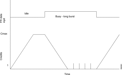
Credits are accumulated at a fixed rate with the normal frame relay feature based on the connections specified minimum information rate/committed information rate and the average frame size. With ForeSight frame relay, to be discussed in detail later in this chapter, credits are accumulated at a variable rate based on CIR as well as the instantaneous available bandwidth on the packet trunks in the network.
Cmax is the maximum number of credits that may be saved. It also represents, therefore, the maximum number of packets that a connection may send in rapid succession. Once the connection has used all of its available credits, it is required to cease sending packets until it has been awarded another credit.
Since frames received from the user equipment typically are broken into multiple packets, Cmax is typically set to the number of packets resulting from the average frame size. This allows a frame to be received in the FRP, packetized, and sent without incurring any unnecessary delay in the FRP. Conversely, setting Cmax to 1 limits the connection to its configured minimum bandwidth unless ForeSight is enabled on the connection.
If a connection is forced to withhold packets until it receives additional credits, space is needed to store those packets. The amount of buffer space available for this purpose is specified, in bytes, by VC_Q. The default buffer space is 64 Kbytes per connection.
Figure 10-12 shows two cases. Case A shows an example where there is sufficient bandwidth and credits available to transmit the frame of data immediately at the peak bandwidth. Case B shows an example where the frame of data is transmitted at the peak rate until credits are exhausted. Then the remaining frame of data is transmitted at the minimum guaranteed.
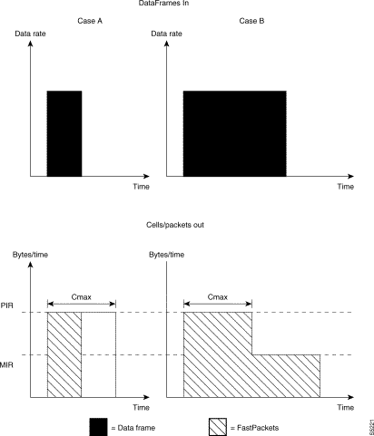
Explicit Congestion Notification is a form of flow control to signal the onset of network congestion to external devices in an IPX frame relay network. ECN detects congestion primarily at either the source or at the destination of network permanent virtual circuits.
To be effective, external frame relay devices should respond correctly to control the rate at which they send information to the network. This feature results in data transmission at the optimum rate for the channel and reduced possibility of packet loss due to excess bursts by the external device.
The Explicit Congestion Notification bits may be set as a result of congestion detected at either the transmitting end of the network at the FRP in the source node or at the receiving end of the network at the FRP in the destination node. ECN does not necessarily detect congestion that may occur at intermediate nodes in the queues of the NTC or AIT trunk cards. The ForeSight feature, discussed in a later section, is an additional form of control that addresses this problem.
Refer to Figure 10-13 illustrating a simple two-node frame relay network for the following discussion. A user device, typically a router, connects to one of the four physical ports on an FRI/FRP card set in the IPX. At the source node, Node alpha, the FRP queues the data in a separate input buffer for each PVC. At the destination node, Node beta, the FRP queues the data to be transmitted to the user device in a single output buffer for all PVCs. (Actually, there are two buffers for each port, one for high priority data and another for low priority data as will be discussed later in this section).
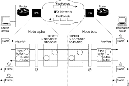
Typically, network congestion occurs at the source of traffic. This can occur when the traffic being generated by the source device momentarily exceeds the network bandwidth allocated. ECN can be used at the source to relieve congestion at this point.
For this example, let's examine frames originating at the left hand side of Figure 10-13 and arriving at the destination user device on the right side of the figure. As frames are received from the source user device they are queued at the input buffer in the FRP at Node alpha. The FRP monitors the depth of the data in the input buffer for each PVC. When the frame relay data in this queue exceeds a preset threshold, VC Q ECN threshold, the FRP declares that this particular PVC is congested.
When congestion is declared, the forward direction is notified by setting the FECN bit in the data header of all outgoing data frames [1B] towards the network (alpha to beta). This will be detected by the destination user device (not FRP) and may or may not take some action to limit the data being applied to the network.
At the same time, the BECN bit is set in all outgoing data frames for this PVC towards the source device (connected to alpha) [1C] to notify equipment in the reverse (backwards) direction. The source device may be able to restrict the rate at which it transmits frames in an attempt to reduce the congestion.
In a similar manner, the two ECN bits may also be set as a result of congestion detected at the destination side of an IPX network. This may result when a large number of PVCs from all over the network all terminate on a single FRP port at the destination node. For this example, let's look at what may happen at the FRP in Node beta.
As frames are received from the source user device they are queued at the output buffer in the FRP at Node beta. The FRP monitors the depth of the output buffer for each port on the FRP. When the frame relay data in this queue exceeds a preset threshold, PORT Q ECN threshold, the FRP declares that this particular port is congested.
When congestion is detected, the FRP sets all FECN bits in frames for all PVCs transmitted in the forward direction to the destination user device [1B] as well as all BECN bits in frames [2B]for all PVCs terminating at this port in the network. The net effect is approximately the same except the ECN mechanism affects all PVCs on a port at the destination whereas source ECN affects only individual PVCs that are congested.
ForeSight provides congestion avoidance by monitoring the transmission of FastPackets carrying frame relay data throughout the network and adjusting the rate at which data is allowed to enter the network. ForeSight allows the FRP card to send packets at a rate that varies between a minimum and a maximum based on the state of congestion in the network along the route.
When the IPX receives an initial burst of data from a frame relay user device, it sends this data out on the network at a rate set by the Quiescent Information Rate (QIR) parameter as shown in Figure 10-14. This rate is usually set higher than the Committed Information Rate guaranteed the user.
The FastPacket and ATM trunk buffers used by ForeSight connections are separate from the buffers used by normal frame relay connections. If the initial FastPackets do not experience any congestion on the network, the information rate is stepped up in small increments towards a maximum set by the Peak Information Rate (PIR).
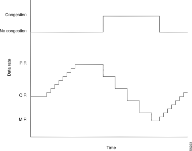
If the FastPackets are processed by a node where there is congestion (trunk card buffers close to being full), an explicit forward congestion notification (EFCN) bit in the FastPacket header is set. When this is packet is received at the destination node, the EFCN bit is examined by the destination FRP card. The far end FRP card then sends a message in the reverse direction (using the RA bit) to indicate the congestion to the near end node.
When the congestion message is received at the source FRP, the data rate is reduced in larger increments towards a Minimum Information Rate (MIR), the minimum guaranteed data rate for the connection. The FRP restricts the bandwidth allocated to the connection by reducing the rate that it issues credits to the PVC.
The connection transmit and receive data rates are controlled separately as the congestion may be present in one direction but not the other. The data rate allocated to the connection is directly controlled by the rate at which the IPX Credit Manager allocates credits. Without ForeSight, the credit allocation is based on MIR and credits are allocated statically.
With ForeSight the credits are allocated dynamically providing a much better utilization of network bandwidth. The net effect is to provide greater throughput for bursty connections when the network has available bandwidth yet preventing congestion on the network when the extra rate cannot be accommodated.
ForeSight can be enabled for a frame relay class. If a class is configured with ForeSight enabled, any new connection added using that class will automatically have ForeSight enabled. Once the connection is added, ForeSight can be disabled. For maximum benefit, all frame relay connections should be configured to use ForeSight when it is installed.
As part of the calculation of the ForeSight algorithm, the IPX measures the round trip delay for each ForeSight connection in the network. This delay is measured automatically by sending a special test packet over the connection. The far end FRP returns the packet and the round trip delay is measured this packet is received at the near end. This delay essentially consists of transmission delay as the test packet is a high priority packet type and experiences minimal processing and queuing delays. Since the network topology can change without notice (due to reroutes, etc.), this delay is measured periodically.
A Test Delay (tstdelay) command provides additional information about connection delay to the user. This test is performed only on command and, since normal frame relay FastPackets are used, includes the delay caused by processing and queuing throughout the connection. The delay factor is stored and available for display using either the Test Delay (tstdelay) command or Display Connection (dspcon)command.
ForeSight requires communicating the connection congestion status from the terminating end of a PVC back to the originating end of a PVC. But when a connection extends across two or more independent StrataCom networks, a means must be found to communicate the connection status between the networks for ForeSight to operate properly. This is accomplished in a manner similar to that just described for the Frame Relay NNI in the "Network-Network Interfaces" section earlier, except that ForeSight uses a Consolidated Link Layer Management (CLLM) message protocol at the junction port of the two independent networks.
An example, illustrated in Figure 10-15, has a frame relay connection originating in StrataCom Network A and terminating in StrataCom Network B. Congestion occurring in Network A is detected in FRP #2, which sends a congestion message back to FRP #1. Congestion occurring in Network B, however, is detected in FRP #4, which returns a congestion message back to FRP #3 at the network-to-network interface to Network B.
Periodically, FRP #3 monitors its VC queue congestion status for all the PVCs at the ingress of Network B. A message, using the CLLM protocol, carrying network status is returned to the NNI port at FRP #2. If no connection is congested, the message will still be sent across the port but there will be no connection DLCI entries listed.
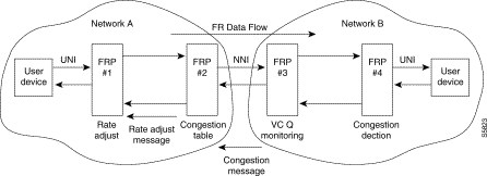
FRP #2 builds a software congestion table listing only internetwork connections experiencing congestion in Network B. Each entry in the congestion table initiates a rate adjustment message that is transmitted across Network A to FRP #1 using a special PCC control packet, the Operation, Administration, and Maintenance (OAM) packet type. If no message is received from FRP #3 after one second, it is assumed there is no congestion on any of the PVC segments in Network B and the congestion table is cleared.
A message indicating congestion on a connection results in a downward rate adjustment and a "Other Network Congestion" indication for each PVC segment experiencing congestion in Network B. The rate adjustment is as follows:
1. If Frame Loss has occurred or the FRP #2 transmit queue is full, a fast down rate adjust signal is sent.
2. If the FRP #2 transmit queue depth exceeds the ECN Threshold, or if the last EFCN bit is set, or if an Other Network Congestion message has been received, a down rate adjust signal is sent.
3. If no congestion is experienced in either network, an up rate adjust signal is sent.
Under conditions of network overload, it may become necessary for the frame relay service to discard frames of user data. Discard Eligibility is a mechanism defined in frame relay standards that enables a user device to mark certain frames to be discarded preferentially if this becomes necessary. This frame discard mechanism can be disabled on a port by port basis by software command.
One bit in the frame relay frame header (DE) is used to indicate frames eligible for discard. User devices may optionally set this bit in some of the frames that they generate. This indicates to the network that if it is necessary to discard frames to prevent congestion, to discard frames with the DE bit set first.
User frame relay data is buffered at the entry point to the network in a separate buffer for each frame relay port. The size of this buffer is specified when the port is defined (using the Configure Frame Relay Port (cnffrport) command).
When configuring a port, the network operator enters a `DE Threshold' parameter, specified as a percentage of the input buffer. During normal operation, when the PVC buffer is filled above this threshold, any new frames received with DE set will be immediately discarded. Only frames not marked DE will be accepted and queued for transmission. This has the effect of discarding frames before they are applied to the network where they may cause congestion. This function, however, is effective only if the user sets the DE bit.
StrataCom frame relay connections also employ another feature, called Internal Discard Eligibility, in an attempt to prevent network congestion. It does not depend on the user to set the DE bit.
Frames received above the CIR with the DE bit not set are monitored in a sliding window, Tc, and decrement a counter in the FRP port. When the counter reaches a certain point, Bc, the IDE bit is set by the port before the frame is queued for transmission. Any node in the network these frames encounter congestion, they will be discarded.
Internal DE is a reserved bit in a StrataCom trailer label at the end of the last FastPacket or ATM cell for the frame. At the receiving FRP, the system can be instructed to map the IDE bit to the DE bit or not as a user option.
Cell Loss Priority (CLP) is a feature that allows FastPackets to be discarded in a selective manner. If the network is congested and packets must be discarded, packets with the CLP bit set will be discarded before other packets. The CLP bit is located in the control byte of the FastPacket header (refer to Figure 10-2) or ATM cell.
The CLP bit is set by the NTC card for either of two conditions:
There are two CLP thresholds associated with NTC or AIT bursty data queues, a high threshold and a low threshold. If the high threshold in the queue is exceeded, FastPackets or cells will be discarded to prevent network congestion. They will continue to be discarded until the queue fill drops below the low threshold.
Frame relay virtual circuits can be designated as either high priority or low priority. This is used to reduce the circuit delay for delay-sensitive protocols like SNA. The Configure Frame Relay Channel Priority (cnfchpri) command is used to set the priority for each PVC. The priority set is communicated to the user device via LMI.
Each FRP has two output buffers for frame relay data, one for frames received with high priority, one for low priority frames. Data in the high priority frame relay buffer is unloaded and transmitted to the user device before any data in the low priority output buffer is unloaded. Since the priority basically affects the unloading of the far end FRP port queue, changing the priority requires that the IPX be able to communicate to the remote end of the connection.
There are two connection parameters that may be entered in one of two formats: StrataCom format and standard Frame Relay format. You enter which parameters are being used with the cnfsysparm command. Refer to Table 10-1 for the parameters that can be chosen. Note that these parameters are not numerically equal.
| StrataCom Parameters | Standard Frame Relay Parameters |
Peak Information Rate (PIR) | Excess burst (Be) |
VC Queue Depth (VC_Q) | Committed burst (Bc) |
Minimum Information Rate, MIR—A connection's minimum bandwidth (information rate) is specified in Kbps. This is used by ForeSight algorithm and represents the lowest information rate that will be assigned when there is congestion on the network. This rate will be reached only during times there is congestion over an extended time. MIR can be set from 2.4 to 2048 Kbps.
Committed Information Rate, CIR—A connection's minimum bandwidth (information rate) is specified in Kbps. It represents the minimum bandwidth that is guaranteed to be available to the user. If a user transmits data at a rate exceeding CIR, the DE bit will be set after a time to indicate those cells may be selectively discarded. CIR can be set from 2.4 to 2048 Kbps.
Peak Information Rate, PIR—This parameter is also used by ForeSight. It is a connection's peak bandwidth (information rate) that the connection may use during data bursts when there is excess bandwidth available and no congestion on the network connection. PIR can be set from 2.4 to 2048 Kbps.
Excess burst bandwidth, Be—If frame relay standard parameters are used, excess burst bandwidth (Be) is specified in place of PIR. Be is specified in the range from 0 to 65,535 bytes. PIR is related to Be by:
Burstiness Coefficient, Cmax—A connection's minimum bandwidth specifies, indirectly, the minimum number of packets per second that a connection is allowed to generate. However, a connection is allowed to exceed that minimum for short bursts. Cmax specifies, in packets, the allowed size of those bursts. This value is also used in allocating packet trunk buffer space. Cmax is a value in the range 1 to 255. If MIR is less than port speed, the larger Cmax is set, the smaller the delay in the source FRP. Increasing Cmax can have the same effect as increasing MIR. However, large Cmax can cause occasional congestion on the IPX trunks.
Buffer Allocation Parameter, VC_Q—VC_Q specifies the maximum queue size, in bytes, reserved in the FRP for the connection. As such, it sets the maximum allowable delay in the source FRP. It can have a value of from 1 to 64 Kbytes. This is a buffer where the frame is held before transmission through the credit manager. It is necessary because the external device can transmit frames to the port at the port speed while the credit manager imposes a maximum FastPacket rate on the connection.
Committed Burst Bandwidth, Bc—If frame relay standard parameters are used, the committed burst bandwidth (Bc) is specified instead of VC Q. Bc is specified in the range from 1 to 65,535. VC Q is related to Bc by the following:
Explicit Congestion Notification queue depth, ECN Q—This parameter sets a threshold in the input VC Q buffer on the FRP for the connection. When exceeded, both the FECN and BECN bits are set in the frame relay frame. FECN bits are set in any frames sent into the network and BECN bits are set in any frame whose DLCI matches a connection with a congested VC Q. ECN Q can be set separately for both the transmit and receive directions.
Quiescent Information Rate, QIR—QIR is the initial port transmission rate utilized for ForeSight connections after a period of inactivity. The initial QIR can be set by the network administrator at some value between the Minimum Information Rate and the Peak Information Rate.
Percent Utilization factor, %utl—Indicates what percent of the CIR that will actually be used. If the port is expected to be fully utilized, the IPX will reserve enough depth in the VC Q to handle the traffic. If a lesser value of utilization is set, the IPX will reduce the VC Q depth reserved for the connection. This, correspondingly, reduces the packets per second reserved for the port.
Typically if the port is expected to handle few, high speed inputs or if ForeSight is used on the connection, leave the% utilization factor at 100%. If there are many low speed inputs, you may want to reduce the utilization factor based on the assumption that not all connections are going to be active at any one time.
Connection Type—The connection type, (FST/fr), specifies whether the connection is to utilize the ForeSight option (FST) or if it is only a standard frame relay connection (fr). Both frame relay and ForeSight are purchased options.
Frame relay can be enabled without ForeSight in which case only congestion in the FRP queues will be detected and the bandwidth allocation for the connection is static. Additionally, if ForeSight option is enabled, congestion along the network connection will be detected and the connection's bandwidth allocation dynamic.
All parameters can use the default values from the frame relay connection class specified. The user may, however, explicitly specify any bandwidth parameters when establishing connections. The values for the minimum bandwidth (MIR), quiescent bandwidth (QIR), and maximum bandwidth (PIR) in both directions are specified in Kbps. The user can override the default for any, or all, of the bandwidth parameters in the Add Connection (addcon) command or the user can adjust any of these values after the connection is made using the Configure Frame Relay Connection (cnffrcon) command.
The software checks the validity of the values entered. It checks in the Configure Frame Relay Connection and Add Connection commands that the sum of the MIR is less than or equal to the line speed of the port. A warning message is generated if it is exceeded. The PIR value is checked against the line speed of the port for all connections. If this is exceeded, the user receives a warning message but the change will be made.
In selecting routes for the connections, the system software checks the bursty data buffers to see if the network will support the proposed connection. If there is not enough bandwidth, then another route will be selected or the connection will not be routed.
Data is received by the FRP from the user equipment in frames that may vary in size from 5 to 4510 bytes. Each of these frames must be broken into pieces to be encapsulated in FastPackets. The number of packets from one frame depends on the size of the frame.
When a connection is added, the IPX verifies that there is enough packet bandwidth to support at least the minimum information rate. To do this, the IPX converts the minimum information rate from Kbps to packets per second for loading considerations.
The number of packets that result from a frame is calculated as:
For example, assume a connection with a minimum information rate of 256 Kbps.
Minimum bandwidth | = 256Kbps x1000/160 bits per FastPacket | = 1600 packets/sec. |
The MIR should initially be set to the required CIR for the connection and the percent utilization factor for ForeSight connections should be set to 100%. This is a very conservative setting and will give full availability to the connection(s) as well as assuring the user always receives the full CIR or higher.
In this case, the IPX will assign new connections to a packet trunk until the sum of the minimums equals the available bandwidth of the packet trunk. If, after time, if it appears that the packet trunks are underutilized, the utilization factor may be reduced. This allows the IPX to assign more connections to the packet trunk.
There is an inverse relationship between overall connection delay and network congestion. An increase in MIR results in a decrease in end user delay but increases the probability of packet trunk congestion.
If minimum bandwidth is adjusted for a working connection, the system may reroute the connection. However, if the speed is changed by only a small amount, the connection will not be rerouted. Since the bandwidth used can be asymmetrical (greater in one direction than the other), the user can specify the MIR differently for each direction of a connection.
The Peak Information Rate (PIR) parameter is used to set an upper limit to the transmitted data rate when ForeSight is being used. When there is unused packet trunk bandwidth, the transmitted rate is allowed to climb to the PIR. If there are few connections on the packet trunk or if the MIRs are set at or close to the CIR, there is less likelihood of the packet line getting oversubscribed and the PIR can be set at or near the access rate of each connection. However, if the this is not the case, the PIR should be set at some level above QIR but less than the access rate.
The minimum that PIR can be set by the user is the CIR required by the circuit. The maximum is 2048 Kbps, which is the maximum port speed a FRP card permits. It is suggested that PIR be initially set to the access rate (AR) of the user device connected to the FRP port. It does little good to set PIR greater than AR as the user device will limit the maximum data rate to AR. PIR must be set to a rate greater than QIR.
Quiescent Information Rate, QIR, is used on ForeSight connections to set the initial burst rate. It must be set somewhere between MIR and PIR. ForeSight then modifies the transmit rate up or down depending on the bandwidth available. If the application consists of short bursts as with transaction processing or database inquiry, setting QIR high is useful in getting a quick user response. It is less effective when the data transmission consists of long intervals of activity.
CIR is generally specified by the usage subscribed to, or purchased, by the user. This is the guaranteed minimum data rate that is guaranteed to the user under all network conditions. If there is no congestion on the network, the user will experience higher throughput. The system uses CIR to determine the setting of the DE bit in the frame relay frame and the CLP bit in the ATM or FastPacket header.
The system calculates the Committed Burst (Bc) and Burst Duration (Tc) from the CIR, VC_Q, and Access rate for the port as follows:
Bc = VC_Q /[1-(CIR/AR)] | and | Tc = Bc/CIR |
If the user does not know what CIR to specify initially, the network administrator needs to know the port speed, the bandwidth needed by the user of the connection, and the average frame size. Determining these parameters may be difficult, especially for new systems. Generally, CIR for a non-Foresight connection should be set to a value at least 1/3 greater than the heaviest expected continuous load on the connection to prevent excessive queuing delay and data loss in the FPR. CIR should not be set greater than the port speed as this wastes network bandwidth.
After a frame relay connection has been up and running for a time, the statistics gathered by StrataView Plus can assist in fine tuning frame relay connections. Statistics that should be observed to monitor this include:
If a user has a low percentage of traffic sent above the CIR, and a low or zero number of BECN frames, the CIR may be reduced without sacrificing performance. If a high percentage of traffic sent above the CIR, the user may be able to improve application performance by subscribing to a higher CIR.
Prior to release 7.0, the system calculated CIR from MIR as follows:
It is important to remember that the maximum data rate supported by a FRP is about 2 Mbps and can be allocated to only one port or spread over the four FRP ports. In general, setting VC Q depth to the default of 65535 is recommended for new installations. However, this may result in an excessive amount of delay if the CIR is low.
If there are many connections with relatively small CIR values originating from a port, then there is a possibility that the entire memory pool becomes allocated. A few connections could unfairly utilize memory and cause data loss on all connections. In this case, values should be set according to some suggested recommendations listed below.
1. CIR equals port speed, frame size is constant—set VC_Q = frame size.
2. CIR equals port speed, frame size varies—set VC_Q = 5X avg. frame size.
3. CIR less than port speed, frame size is constant—set VC_Q = 25X avg. frame size up to the max. of 65536 bytes.
4. Average frame size is unknown—set VC_Q = 65536 bytes.
Without ForeSight, the initial data rate is fixed at the CIR. With ForeSight, this can be adjusted by setting QIR considerably higher than CIR (MIR). If MIR is equal to port speed, Cmax can be small. If MIR is much less than the port speed, a value that can result in reducing delay is to set Cmax appropriate to generate sufficient packets to send two or three average frames in a burst.
If there are relatively few frame relay connections and the average frame size is small for most of them, it might be feasible to set high Cmax values for the connections. However, high values on too many connections originating at many different ports can cause congestion on the trunks. It is recommended that the total of the Cmax values for all connections using a given trunk not be allowed to exceed the BData Q Depth for that trunk. A suggested procedure in choosing Cmax are:
1. MIR equals port speed, frame size is constant—set Cmax = 1.
2. MIR equals port speed, frame size varies—set Cmax = 5
3. MIR less than port speed, frame size is constant—set Cmax = [(avg. frame+22) divided by 20]. This equals the number packets needed for one average frame.
4. Average frame size is unknown—set Cmax = 30 if utl is greater than 75%, 20 if utl is 50 to 75%, 10 if utl is 25 to 50%, and 5 if utl is less than 25%.
Some suggestions in choosing ECN Q depth is to set it to 1 or 2 times the mean frame size. If an approximate mean size is not available, refer to the following suggestions.
1. Mean frame size is known—set ECN Q Depth = 2X mean frame size.
2. Mean frame size can be estimated—set ECN Q Depth = 500, 1000, or 2000 for small (bytes or hundreds of bytes) frame size, medium (500 to 1000 bytes) frame size, or large (1000 to 2000 bytes) frame size, respectively.
3. Mean frame size is unknown—set ECN Q Depth = 2000 if the traffic is primarily batch or 1000 if primarily transactions.
A port on a FRP frame relay card is defined by the following parameters. These parameters can be observed using the Display Frame Relay Port (dspfrport) command and changed using the cnffrport command.
Port Location—This is the physical card slot where the FRP card is located in the IPX and the port number on the card (1 to 4) being assigned.
Clock Speed and Type—This is the data clock rate of the port (i.e. port speed) and how the port clocking is to be configured. Allowable port speed ranges from 2.4 to 2048 Kbps. Each port can be configured as either DCE or DTE. In addition the port clock can be configured normal clocking or loop timing.
Port ID—This is a Data Link Connection Identifier number assigned to the port. It may be left to the default of 0 if not using bundled connections as it is not used by the IPX. For bundled connections, where the user does not have to enter a specific DLCI, this number is used as the beginning DLCI of the mesh bundle.
Port Queue Depth—Is the number of bytes to allocate to the transmit port buffer for this frame relay port. The maximum size that can be allocated is 65,535 bytes. This should be sized set to some multiple of the average frame length being transmitted by the user device and the length of the bursts expected.
DE Threshold—Is the port queue discard eligibility threshold above which frames received from the user device with the DE bit set will be discarded to prevent queue overflow. Valid entries for this parameter range from 0 to 100% with reference to the capacity of the virtual circuit queue. A setting of 100% effectively disables DE for the port.
Signalling Protocol (LMI mode)—This indicates the Local Management Interface mode and protocol to be used for this port. The basic LMI can be enabled or disabled, as well as the asynchronous update process and the GMT time feature. Refer to Table 10-2 for valid entries and their description.
| LMI = | LMI Status | Protocol Used |
|---|---|---|
0 | Disabled | None |
1 | Enabled | StrataCom LMI, asynchronous update process (unsolicited sending of update status messages) and GMT time features are enabled. |
2 | Disabled | None |
3 | Enabled | StrataCom LMI but asynchronous update process disabled. |
4 | Enabled | UNI uses ITU-T Q.933 Annex A parameters. |
5 | Enabled | UNI uses ANSI T1.617 Annex D parameters. |
6 | Enabled | NNI uses ITU-T Q.933 Annex A parameters. |
7 | Enabled | NNI uses ANSI T1.617 Annex D parameters. |
LMI Protocol parameters—If LMI is enabled for the port, some or all of these various parameters may be modified to tailor the LMI to the user device attached to the port. These parameters described in Table 10-3.
| Parameter | Valid Entries | Description |
|---|---|---|
Asynchronous Status | y or n (n) | Defines if status reports should be sent asynchronously to the connecting device over the IPX frame relay LMI channel. If no, IPX waits for a status request from the connecting device. |
Polling Verification Timer | 5-30 sec. (15) | Sets the interval for the keepalive timer. This should be set to 5 seconds more than the heartbeat timer in the user device. |
Error Threshold | 1-10 (3) | Sets the threshold for errors in the signalling protocol before an alarm is generated. |
Monitored Events Count | 1-10 (4) | Indicates how many events in the signalling protocol should be monitored for keepalive. |
Communicate Priority | y or n (n) | Indicates if the IPX should communicate the PVC port SNA priority (high or low) to the user device. |
Upper RNR Threshold | 0-255 (75) | Sets the upper threshold (as a % of the max. VC Q depth) above which a congestion indication is sent to the user device. |
Lower RNR Threshold | 0-255 (25) | Sets the lower threshold (as a % of the max. VC Q depth) above which an end to congestion indication is sent to the user device. |
Min. flags per frame | Any value > 1 (1) | Indicates the number of flags to expect between frame relay frames. |
In some cases, determining a reasonable port speed may be difficult. For example, if a user has eight 64 Kbps lines between a hub site and several remote sites, a first estimate for port speed would be 512 Kbps. However, if only 30% of the line capacities are used then 256 Kbps would be a more than adequate port speed.
If the approximate total bandwidth needed is known, port speeds should be set to at least 1.5 times the total bandwidth needed. Higher settings may be used to reduce delay or allow room for future growth. In cases where older technology (e.g. modems or DDS lines) are being replaced with frame relay, port speeds should be set to the total of the line bandwidths currently being used until the bandwidth needed has been determined from statistics.
For new networks where the bandwidth needs are unknown, start out with a high port speed and adjust downward based on collected IPX statistics. If the speed of the line being replaced is known, use it. If not, set the MIR and port speed the same and use a low %utl factor, i.e 100 divided by the number of connections to the port.
The setting for port queue depth sets a maximum allowable delay in the terminating FRP. Larger settings can reduce the probability of discarded frames. In most cases, end-user delay caused by queuing in the FRP will be much less than end-user delay caused by lost data. Therefore, larger settings can reduce delay by reducing discarded frames. Unless there is good reason to change it, leave this at the default of 65,535 bytes.
If the mean frame size is known, set the ECN Q threshold to twice the mean frame size. If it is unknown, start with a value of 2000. Once FECN and BECN support has been implemented in end-user devices, the setting for ECN Q depth can be used to reduce network delay, congestion, and data loss.
Prior to adding connections, Port Concentrator Shelf (PCS) ports are configured from the IPX or IGX user interface with the cnffrport command. The parameters associated with the cnffrport command, along with the complete set of commands available for frame relay ports, are described in the Command Reference Manual.
PCS ports are specified by <slot.port>, where slot is the slot number in which the PCS-connected FRM-2 or FRP-2 card resides, and port is the PCS port in the range 1-44.
Connections are activated via commands. The commands are concerned with the activating, configuring, and reporting of statistics for frame relay connections. Each of the commands described in the frame relay chapter of the Command Reference Manual is supported for PCS frame relay connections.
When not using the StrataView Plus Connection Manager, the following commands are required to set up a frame relay connection:
Step 2 Use the cnffrport command to establish parameters for the port.
Step 3 Use the dspcls command to view existing frame classes. Select a class if a suitable class exists, otherwise create a class with the cnffrcls command.
Step 4 Access the node at the remote end of the proposed connection with the vt command, and again use the upfrport and cnffrport commands as in Step 1 and Step 2 above.
Step 5 Create the connection with the addcon command, specifying the class selected in Step 3 above.
The software checks the validity of the values entered. It checks in the configure frame relay connections (confrcon) and add connection (addcon) commands to ensure that the sum of the MIR is less than or equal to the Port Concentrator port speed. A warning message is generated if it is exceeded. The PIR value is checked against the Port Concentrator port speed for all connections. If this is exceeded, an warning message is generated but the change will be made. There is no validity checking of the MIR or the PIR values against the concentrated link speed.
Grouped connections gathers up to 16 PVCs having the same routing characteristics. Each connection group is treated as one connection for routing. The individual circuits do not have to be added at the same time, or be in any numerical sequence, and the can be located on any Port Concentrator. The only restriction is that each circuit in the group must be in the same IPX/IGX node, follow the same routing path, and terminate on the same far-end IPX/IGX node. Port Concentrator-terminated frame relay connections and FRM or FRP terminated connections may also be grouped together.
Maximum throughput through the PCS is 800 frames per second for each module of 11 logical ports.
The maximum number of connections available per FRM-2 or FRP-2 card is 252 connections. Thus, total number of connections on all 44 ports cannot exceed this limit. This is an average of 5 connections per port, but any mix is acceptable as long as the total of 44 ports does not exceed 252 connections
As described under "Frame Processing by the PCS", below, additional processing of data frames is required for connections utilizing the PCS.
The amount of delay introduced depends on a large number of network characteristics. In an average application of a PCS port operating at 64K bps, utilizing 200-byte frames with the remainder of ports on the concentrated link operating at 50% capacity, the additional delay caused by a PCS at either end of a connection is in the range of 25ms more than the same connection directly through FRM-2 or FRP-2 ports.
The PCS performs the minimum amount of work necessary to process incoming data frames. Besides multiplexing/demultiplexing data between the concentrated link and its 11 ports, the PCS does not handle any other frame relay features. The FRM-2 or FRP-2 performs all frame relay functions for the 44 PCS logical ports as if they were physical ports. This includes functions of permanent virtual circuit management, ingress queuing management, and signaling protocol support. Other functions, such as egress queuing management and statistics gathering are performed by the PCS.
Figure 10-16 below shows an example of a PCS frame relay connection within an IPX/IGX/BPX network. Figure 10-17 illustrates the breakdown of PCS frame relay data entry into IPX/IGX FastPackets. The frame formats at point (a), (b) and (c) shown in Figure 10-16 are described in greater detail in Figure 10-17.
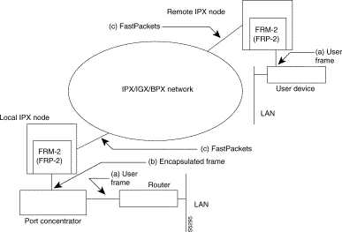
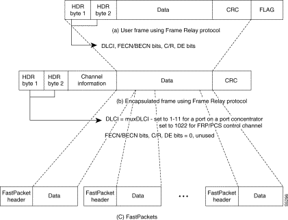
The muxDLCI specifies the port number on a PCS which is either a source or a destination of that frame. A frame containing the control message between PCS and FRM-2 or FRP-2 will have the muxDLCI set to 1022. The control information includes code download, port configuration, port status and statistics, and failure event reporting. This default DLCI of the control frame is not configurable in release 1.0.
The IPX frame format is used only on the concentrated link. The PCS appends the IPX frame header and CRC checksum when it passes frame to the FRM-2 or FRP-2. The FRM-2/FRP-2 removes the IPX frame header and CRC before constructing the FastPackets. Once the FastPackets arrive at the destination FRM-2 or FRP-2, the FRM-2 or FRP-2 reconstructs the original user data frame. The IPX header and CRC is then added before a frame is sent to the PCS. The PCS removes the IPX header and CRC and sends the frame out on the port as specified in the muxDLCI.
Ingress queues are managed on a per-PVC basis, and are implemented on the FRM-2 or FRP-2 card. From PCS to FRM-2 or FRP-2, there are no ingress queues since concentrated link speeds are fixed at 512K bps and the maximum for each set of 11 ports must always be 448K bps or less. The Foresight egress queue is managed on a per-port basis (rather than per-connection as is done on ingress). This queue is implemented on the PCS identically to existing FRM-2 or FRP-2 egress queues (Figure 10-18).
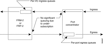
The frame header for incoming frames to the PCS contains the DLCI from the user device. This DLCI, along with the Port Concentrator port number (muxDLCI), is used to determine a unique permanent virtual connection. The FRM-2 or FRP-2 implements a separate ingress queue for each PVC. Once a frame is received by the FRM-2 or FRP-2, the frame is queued up in its appropriate PVC queue on the FRM-2 or FRP-2 based on the DLCI. The frame is then routed to the destination node.
The destination of a frame may be another FRM-2 or FRP-2 port in which case the data will be passed to the user device. If the destination of a frame is another PCS, the FRM-2 or FRP-2 card will also receive the packet. In either case, the FRM-2 or FRP-2 will determine the destination port number from the virtual circuit identifier found in the FastPacket header. The frame is reconstructed and placed in the corresponding port queue. For a frame destined for an FRM-2 or FRP-2 port, the frame is placed directly on the physical port queue and transmitted out to the user device. For the frame destined for a PCS port, the packet is placed in the logical port queue and transmitted out on a concentrated link. The PCS then passes the data out to the user device.
If the packet is destined for an FRM-2, FRP-2, or PCS port, after reconstructing the frame from the FastPackets, the FRM-2 or FRP-2 replaces the source DLCI with destination DLCI before placing the packet into the port queue.
The frame containing LMI and CLLM information and the control information between FRM-2 or FRP-2 and Port Concentrator has priority over user data frames.
ForeSight will be supported on a frame relay connection terminating on a PCS. The FRM-2 or FRP-2 handles the ForeSight algorithm for all 44 ports in the ingress direction. The egress direction is handled by the PCS. On ingress, since the concentrated link speed will always be higher than the total port speed of all 11 ports, there will always be bandwidth available on the link. However, when the network is congested, the PVC receive queue on the FRM-2 or FRP-2 can be full in which case some data receiving from the concentrated link will be dropped by the FRM-2 or FRP-2.
On egress, the FRM-2 or FRP-2 passes the frame to the Port Concentrator at the concentrated link speed. The Port Concentrator maintains the per port egress queue for ForeSight. The Port Concentrator reports egress congestion status to the FRM-2 or FRP-2. The FRM-2 or FRP-2 forwards the congestion status to the remote end of the connection using standard ForeSight mechanisms. The Port Concentrator sets egress FECN and ingress BECN bits as necessary based on egress congestion levels. The Port Concentrator also drops DE frames and queue overflow frames as necessary based on egress congestion levels. The related channel and port statistics are also reported to the FRM-2 or FRP-2.
Frame forwarding connections provide a mechanism for connecting non-frame relay frames (HDLC and SDLC). The frame forwarding on a Port Concentrator is implemented in the same way as a normal frame relay connection. When an HDLC frame arrives on a port, the Port Concentrator simply encapsulates the frame in an IPX header and passes it to the FRM-2 or FRP-2 along with the muxDLCI. The FRM-2 or FRP-2 uses the muxDLCI to determine the PVC and route the packet to the destination node. The FRM-2 or FRP-2 at the destination node determines the destination port and places the frame in the appropriated logical port queue.
ForeSight is supported on frame forwarding connections. In addition to supporting frame forwarding on PCS connections, frame forwarding is also supported on PCS-to-FRM/FRP and PCS-to-FastPAD interworking connections.
Network routing decisions within the IPX/IGX/BPX network for a PCS frame relay connection are the same as those for other frame relay connections. The rate parameter specified for connections, together with the utilization parameter for the channels are used to determine the LU (Load Unit) for IPX segment of a connection. The frame relay connection is mapped to the BData-A queue for the non-ForeSight case and to the BData-B queue for the Foresight case. Priority bumping and courtesy downing are also available on a PCS frame relay connection.
Local connections from one PCS port to another are routed to the FRM-2 or FRP-2 card and back. Local switching is not supported by the PCS.
![]()
![]()
![]()
![]()
![]()
![]()
![]()
![]()
Posted: Fri Jan 19 16:43:30 PST 2001
All contents are Copyright © 1992--2001 Cisco Systems, Inc. All rights reserved.
Important Notices and Privacy Statement.