|
|

The LAN connection function allows the interconnection of local area networks (LANs) of the Ethernet type via a wide area network (WAN).
This connection function offers several services:
Access to the Ethernet local area network is through a 10 Base T port (RJ45 connector) or a 10 Base 5 (AUI connector).
At the link level, this interface is characterized by an Ethernet address on 48 bytes known as the MAC (Medium Access Control) address, set by the manufacturer, and the same for all Ethernet equipment.
Each equipment unit has an Ethernet MAC address of IEEE 802.3 format given by the hardware identification and used by the LAN supervision frames.
It always begins with 08-00-6F identifying Philips Communication Systems (PCE). The MAC address is visible in hexadecimal in bloc 3 of the LAN statistics buffer (fields 16 to 1B, see Management Functions Manual, Chapter 1.10.5).
This link level also defines the encapsulation of the network level protocols.
The respective structures of the headers for the four types of encapsulation are given below:
The Ethernet or IEEE 802.3 encapsulation types are possible for the implementation of the IP protocol (Configuration in C41R6). The four types of encapsulation are possible for the implementation of the IPX protocol (Configuration in C54R4).
The equipment sends out at all times supervision frames to check the state of the Ethernet link.
The structure of the Ethernet frame is as follows:
Destination address on 6 bytes Source address on 6 bytes Protocol "9000" on 2 bytes Data on 46 to 1500 bytes CRC check on 4 bytes
The frames are transmitted every two seconds if there is not traffic detected during transmission and reception
Operation in Ethernet/802.3 Bridge mode allows the interconnection (on level 2) of Ethernet networks through X.25 or frame-relay type remote networks.
It is based on knowing the 48-bit physical addresses (MAC) of the equipment connected to the Ethernet local area networks. To accomplish this, self-learning and address filtering functions on the local network side and remote network side are implemented. The equipment proposes the management of static inputs into remote address tables in order to limit distribution on the remote ports as well as distribution on the remote network. Tables are updated according to the information contained in the MAC frames and according to the "aging" timer.
Operation in Router mode allows the interconnection (on level 3) of IP local area networks through X.25 or frame-relay type remote networks.
It also allows the declaration of subnets.
Routing takes place on the basis of several sources of information:
The equipment performing the IP router function has one level 3 address per virtual port called an IP address (see definition of virtual port in § 20.2). Class A, B and C addresses are supported. These addresses are supplied on configuration. The values are stored in non-volatile memory and taken into account when the configuration is confirmed.
The routing function allows the management of several LAN or WAN interfaces. Each virtual port has an IP address; each of these virtual ports is associated with a LAN or WAN connection function. Several network interfaces may be associated with the same WAN connection function.
An IP address is composed of 32 bits (or 4 bytes). It is currently expressed in decimal notation in the form of field1, field2, field3, field4, each of the fields being a decimal digit from 0 to 255 (for example, 15.0.15.0 is written in binary = 00001111 00000000 00001111 00000000).
Any equipment using the IP protocol must have at least one IP address.
Equipment that uses an SNMP administration must have an IP address.
Equipment in bridge mode does not require an IP address to perform bridge functions. On the other hand, equipment in Bridge/Router mode must have an IP address for each of these virtual ports.
When a router receives a datagram intended for an IP address, it must know whether this packet must be transmitted directly to the recipient, or whether it is to be transmitted to a router that will transmit it to the recipient. IP addresses contain sufficient information for this decision to be made. If a router transmits data to a station located on a remote network, accessible via a remote router, the IP address of this router must also be known. If the path to the recipient station is made up of several routers, it is sufficient to know the IP address of the closest router.
For class A networks, the first field of the address (the leftmost) specifies the network number and the class. The next three fields specify the host (station) number and the subnet address, if any. The first field may have a value between 0 and 126, 127 being reserved as a loopback address. This class is interesting for a topology consisting of some large networks each having many stations.
For class B, the first two fields of the address (the leftmost) specify the host (station) number and the subnet address, if any. The first field may have a value between 128 and 191. The second field may have a value between 1 and 254. This is interesting for a topology made up of many networks, each having many stations.
For class C, the first three fields of the address (the leftmost) specify the network number and the class. The next field specifies the host (station) number. The first field may have a value between 192 and 223. The second field may have a value between 0 and 255. The third field may have a value between 1 and 254. This class is interesting for a topology made up of many small networks, each having relatively few stations.
The class used is identified by the first bit(s).
| Class | Number | Class type identifier |
|---|---|---|
A | 1 to 126 | first bit = 0 |
B | 128.1 to 191.254 | first 2 bits = 1 0 |
C | 192.0.1 to 223.255.254 | first 3 bits = 1 1 0 |
As all class A networks have already been allotted through the Internet, a choice must be made between class B and class C.
The Internet organization recommends that each entity should use no more than two network addresses on the Internet. To maintain a notion of networks within an organization, subnetting is possible.
Principle
Subnetting makes it possible to use an address on the Internet and subaddresses within an organization. For this purpose, a mask must be defined for each station and router of an organization in order to distinguish the subnet part and the station (host) part of the addresses.
For example, if an organization requires two internal networks and has a class B address beginning with 128.64.x.x, it is possible to allocate 128.64.1.x to one of the networks and 128.64.2.x to the other (x may be between 1 and 254).
The stations on the Internet can reach the stations of an organization through the network address 128.64. The two subnets form a single network.
Within an organization, the IP addresses are interpreted as being composed of three parts:
The mask which makes it possible to distinguish the subnet in the host part of an IP address has 32 bits and corresponds to the 32 bits of an IP address.
Each bit at 1 of the subnet mask means that the corresponding bit in the IP address must be interpreted as being the net and subnet parts. Each bit at 0 of the mask means that the corresponding bit in the IP address must be interpreted as being the host part. Thus, bits at 1 in the host part are interpreted as being the subnet part of the address.
The last field at 0, because a host part is always required.
Simple mask values are, for example:
| 1 bit | 1 bit | 14 bits | 5 bits | 11 bits |
|---|---|---|---|---|
1 | 0 | X | X | X |
|
| Network (station0 | Subnetwork (subnet) | Station(host) |
Definition of IPX address
An IPX address is made up of several fields:
The network field, origin or destination on 32 bits, designates a unique subnet. When it is equal to 0, this means that the recipient is under the same subnet.
The node field, origin or destination on 48 bits, designates the IEEE 802 address of the destination station.
To build its address, a station only must look at the messages moving on the network to identify the subnet number and then add its own physical address.
The socket field, origin or destination on 32 bits, designates the destination service within the origin or destination station.
This field allows the multiplexing of flows of different applications within the same station (host).
| 32 bits | 48 bits | 32 bits |
|---|---|---|
Network | Node | Socket |
IPX Address
| ||
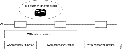
The notion of virtual port makes it possible to define, for the Bridge and Router functions, operating interfaces independent of the WAN protocols (X.25, frame relay, etc.) and value-added services such as compression, circuit reliability, overflow backup.
Of the local type, it is attached to a LAN line and allows communication with equipment connected to the local area network.
Of the remote type, it allows communication through the WAN network with all bridges and routers accessible through connection functions defined by the user. Each remote virtual port is characterized by a set of remote bridges and routers accessible through the same logical interface.
 Notion of Virtual Port
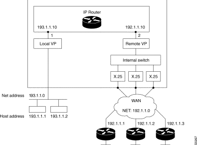
Example 1: 1 local VP, 1 remote VP on an IP router
The equipment is used as an IP Router to connect hosts connected to LAN (IP network 193.1.1.0) to remote equipment belonging to a single IP network (IP network 192.1.1.0).
The remote equipment located on the same IP network (192.1.1.0) may exchange IP frames two by two: a single remote VP must be configured.
 Example 1: 1 Local VP, 1 Remote VP on an IP Router
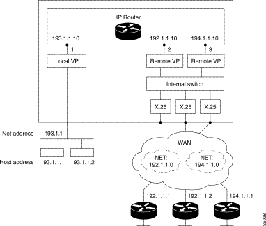
Example 2: 1 local VP, 2 remote VPs on an IP router
The equipment is used as an IP Router to connect hosts connected to a LAN (IP network 193.1.1.0) to remote equipment belonging to two distinct IP networks (192.1.1.0 and 194.1.1.0).
The remote equipment located on the IP network (192.1.1.0) may exchange IP frames two by two: a remote VP must be configured.
The remote equipment located on the IP network 194.1.1.0 may exchange IP frames two by two but cannot dialogue directly with equipment located on the IP network 192.1.1.0: another remote VP is essential.
Communication between equipment 192.1.1.X and 194.1.1.X then becomes possible through the IP router.
 Example 2: 1 Local VP, 2 Remote VPs on an IP Router

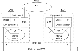
The LAN connection function behaves like a subscriber communicating with one or more remote subscribers via one or more Switched Virtual Circuits (SVCs).
An SVC corresponds to the setup of a virtual circuit between two subscribers.
Depending on the encapsulation mode (see § 20.3.2), an SVC may be dedicated to a protocol (non-multiplexed mode) or can transfer several types of protocols (multiplexed mode) and is independent of the physical medium (PSTN, ISDN, LL).
An SVC may be of two types depending on the WAN network used:
This is the case when equipment is interconnected through an X.25, PSTN or ISDN network.
 Example
The destination subscriber corresponds to a local subscriber in the case of a FR connection (RFC1490).
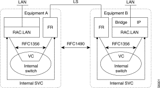
In this case, it is the routing configuration that makes it possible, based on the address of the remote equipment configured by the user, to establish a virtual circuit internally between the LAN connection function and the output protocol.
In every case, a subscriber is characterized by an X.121 address (DNIC ZO AB) with which a virtual port is associated by configuration.
A virtual port corresponds to a set of destination subscribers and hence to a set of SVCs.
The transport of bridged or routed frames on the remote network implements encapsulation mechanisms that depend on the chosen output WAN protocol.
Two encapsulation modes are available:
Internally (LLC), RFC 1356 is the encapsulation method used for the transfer of frames between WAN and LAN connection functions.
Frame grouping service
Specific encapsulation of frames on an X.25 network (hence proprietary) is thus possible in order to benefit from a frame grouping and ungrouping service.
This service allows an increase in the total bit rate on the WAN by grouping during congestion phases.
The smaller the size of the frames to be grouped and the larger the size of the frames exchanged on the WAN, the more valuable is this service.
This service may be applied to the bridge and to the router.
Encapsulation is negotiated during the setup of the SVC with the following values for the NLPID (Network Layer Protocol IDentifier).
Frame encapsulation is in conformity with that of the bridge and router but adds a separator before each frame to allow ungrouping in the remote equipment.
Choice of type of encapsulation
The type of encapsulation is chosen by SVC when the equipment is configured. The user indicates, for each SVC, the protocol(s) to be transferred as well as the encapsulation used (C36R3), and the regrouping mode (C36R3).
The management mode for the LLC and the transport of IP data on X25 are more specifically defined by RFC 1356.
The management mode for the LLC and the transport of IP data on Frame Relay are more specifically defined by RFC 1490.
Each LLC can operate in any of the following encapsulation modes:
Table 15-3 gives the different types of encapsulation possible:
| Mode | Network | Protocol | Call data | Encapsulation | RFC |
|---|---|---|---|---|---|
Non-multiplexed | X.25 | IP CNLP IPX CISCO Eternity Bridge Grouping Eternity Bridge Grouping IP | 'CC 81 80 + 000000 + 8137 D3 D5 | None None None None | RFC1356 |
Multiplexed SVC Configuration | X.25 | IP CLNP Ethernet Bridge with FCS Ethernet Bridge without FCS STP | '00 00 '00 | 1 byte = 'CC 81 '80+'0080C2+'001 | RFC1356 |
FR | IP IPX CLNP Ethernet Bridge with FCS Ethernet Bridge without FCS STP | None None None None | CC 80+000000+8137 81 '80+'0080C2+'0001 | RFC1490 | |
In addition to the type of encapsulation, the user indicates, for each internal or end-to-end SVC:
The type of connection (C36R3):
If the SVC is of the datagram type, the SVC is established on data transmission as long as the protocol is authorized for that SVC.
A request for an SVC is accepted if this SVC is declared to be of the calling, mixed or datagram type and the type of encapsulation proposed in the "User Call Data" field is of the call packet type, otherwise the call is released and a significant event is generated.
The silence duration : (C36R4)
A first timer is set on connection of the LLCs (LAN timer connection function which can be configured for C12R6P16). On its expiration, a second parameterizable timer by LLC called "silence duration" is set before it causes the releasing of the LLCs without traffic.
The value of the silence duration is used to release the LLCs without traffic which are reestablished immediately (maintained mode) or on the transmission of data (datagram). The LLCs can then be reestablished on another medium (case of return to LS after backup by ISDN).
An LLC is released when there is no traffic for a time equal to or greater than the value of the silence duration.
Slow call : (C36R4)
If an LLC is not made and declared to be of the calling or mixed type, a request to establish an LLC is again generated by the equipment after a period of time equal to or greater than the configurable call retransmission value. This is so as not to generate toward the network LLC request that are not satisfied and at too high a frequency.
The Ethernet/802.3 Transparent Bridge function is used for the interconnection (on level 2) of Ethernet networks locally or through a remote network.
A single Ethernet network is proposed in V12.2. WAN/WAN bridging is not offered in V12.2
The operation of a transparent bridge is based on knowledge of the 48 bit physical addresses (MAC) of the equipment connected to the Ethernet local area networks. For this purpose, self-learning and address filtering functions on the local side and remote network side are implemented.
Transparent bridges are thus called owing to the fact that their presence and operation on a network are transparent to the hosts of the network. When a transparent bridge goes into service, it learns the topology of the network by analyzing the source address of the frames that it receives on all its ports.
If, for example, a bridge sees the arrival of a frame on its port P1 - frame sent by host A - the bridge concludes that host A is accessible through its port P1. Based on this principle, a transparent bridge constructs a correspondence table matching a host identified by its MAC address with the port P through which this host is accessible.
The transparent bridge uses this correspondence table to bridge the traffic from a port P(r) to a port P(s). When a frame is received on port P(r), the bridge analyses the destination address of the frame and examines whether this address is contained in the correspondence table. If the table contains an association between this address and a port P(s) -different from the reception port P(r) - the frame is sent over port P(s).
If no association is found, the frame is duplicated and sent over all the ports P of the bridge with the exception of the reception port P(r). Similarly, the broadcast and multicast frames are systematically duplicated and sent over all the ports P of the bridge with the exception of the reception port P(r).
Transparent bridges allow the isolation and hence the reduction of traffic segment by segment.
The equipment proposes the management of static inputs in remote address tables in order to limit distribution on remote ports as well as distribution on the remote network. Tables are updated according to the information contained in the MAC frames and according to the aging time-out.
Supervision frames are transmitted constantly over the Ethernet network in order to check the condition of the physical link.
Applicable standards and documents are the following:
"Transparent Bridging" [802.1] for transparent bridging.
"Spanning Tree Protocol" [802.1d] (not offered in V12.2).
Local filtering by continuous self-learning allows the automatic identification of frames intended for remote stations. Only these frames are transmitted on the remote network for destination equipment located on the remote local area network.
Filtering is carried out by the automatic construction of the local station address list. This construction involves the automatic learning of source addresses of all the frames received by the Bridge on its local network interface.
Filtering obviates the need to transmit to the remote network a frame received on the local network and intended for a station located on the same network. If the destination address is contained in the list of local network stations, this frame is ignored, thereby optimizing traffic on the remote link Otherwise, the frame is transmitted on the remote network (see next chapter).
General broadcast frames (broadcast: destination address = FF-FF-FF-FF-FF-FF) and group broadcast (multicast: destination address whose multicast indicator is at 1) are systematically transmitted on the remote network.
A frame whose path used to reach the associated local area network is not known is transmitted to all the virtual circuits declared by the operator. Only the application of the destination station of the frame replies; the Bridge will consequently, thanks to this response, determine the path associated with the MAC address of the destination station. Any new transmission towards this station results in the transfer of frames over the associated path.
Broadcast and multicast frames are systematically sent over all the declared logical links.
To update the inputs of the filtering tables, a time-out (ageing timer) (C38R1) is set as soon as each input has been updated in order to allow its elimination if the corresponding address is no longer detected on the network. This time-out can be configured by the user on the Ethernet interface as well as the remote interface.
In addition to the filtering carried out automatically by the self-learning of the local addresses, it is possible to add complementary filtering: frames for distant terminals can be filtered by the offset/mask technique on different:
This level of filtering refines the traffic circulating over the remote network. This is a way of avoiding the pointless saturation of the remote link. Thus, if two bridges connect the LANs where the stations are using TCP-IP and XNS protocols to communicate between one another, it is possible to ask the bridges to only allow through the data exchanges using the TCP-IP protocol
The technique used by offset/masking is not limiting and permits other types of filtering (especially on IP addresses...).
This service consists in analyzing every frame received from the Ethernet network and in deciding whether it should be destroyed or whether it should continue its route to the recipient function.
By configuration, the user defines a list of filters each of which embodies three conditions, a decision and a virtual port to which is applied. Each condition includes an offset, a mask and a value.
For a given frame, the condition is satisfied if the field designated by the given offset and masked bit buy bit corresponds to the value. The filter is satisfied if all the conditions are satisfied.
On receiving a frame, the algorithm consists in scanning the filters in order and stopping on the first of them that is satisfied. The decision associated with this filter is then executed, i.e. acceptance or rejection of the frame.
A condition can be complemented (condition + 100): its result is then inverted.
A filter can have a condition zero: this is an all-[ass filter or one that preserves all the frames, depending on the decision.
If none of the filters is satisfied or if none has ben configured, the frame is accepted (this is the choice by default).
The filters are configured in class 50.
To limit WAN broadcasting on remote ports, the user can position static inputs in the remote table addresses. This information comprises:
The implementation of a bridge-to-bridge (Spanning Tree) protocol obviates the need for loopback arrangements which appear when there are several paths of bridges and networks between any two hosts of the architecture.
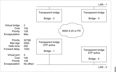 Spanning Tree Protocol
Example 1:
Host A on LAN-1 sends a frame to host B on LAN-2. The two bridges Bridge-2 and Bridge-3 will both receive the frame on their LAN interface and conclude that host A is accessible through their local port.
Each of the bridges Bridge-2 and Bridge-3 will respectively send the frame to Bridge-1 and Bridge-4 through the WAN network.
Bridges Bridge-1 and Bridge-4 will bridge the frame on LAN-2. This frame will again be received by these two bridges on their local interface; Bridge-1 receiving the frame bridged by Bridge-4 and vice versa. These two bridges will conclude that host A is accessible through their local port.
When host B on LAN-2 replies to host A, the response frame will be filtered by Bridge-1 and Bridge-4 who will estimate that this frame is local within LAN-2 since host A is considered to be accessible via the local interface of Bridge-1 and Bridge-4.
The malfunctioning of the transparent bridge in the presence of a loop is even more striking when a bridge processes a broadcast or multicast frame. Let us return to our previous example and assume that host A on LAN-1 transmits a broadcast frame - typically an IP-ARP packet.
The frame is bridged by Bridge-2 and Bridge-3, and then by Bridge-1 and Bridge-4, and received in two copies on LAN-2. These two copies are received by Bridge-1 and Bridge-4, rebridged by these two bridges towards Bridge-2 and Bridge-3, again received on LAN-1, and so on!
The STP algorithm allows loops in a bridge architecture while overcoming the underlying problems mentioned above. This algorithm eliminates the loops of an architecture by positioning the ports of certain points in a blocked state while providing communication between any two hosts of the architecture. The algorithm is broken down into several stages:
Configuration examples
 Principle
| Class No. | Class Name | Equipment 1 | Equipment 2 | ||
|---|---|---|---|---|---|
C44 | Statis routes |
|
| ||
C42 | Corres. |
|
| ||
C41 | IP interface | Local | Remote | Local | Remote |
C36 | Connection table | 90002093 | 90001093 | ||
C35 | VP table | local VP = 3 | remote VP | local VP = 3 | remote VP |
C33 | Table of modules | Local subscriber 93 | Local subscriber 93 | ||
C1R1 | Line | Line 3 = | Line 1 = X.25 | Line 3 = | Line 2 = X.25 |
C1R1 | Address | 900010
| 900020 | ||
| Class No. | Class name | Equipment 1 | Equipment 2 | ||
|---|---|---|---|---|---|
C44 | Static routes |
|
|
|
|
C42 | Corres. IP/X.121 |
|
|
|
|
C41 | IP interface | Local193.107.114.41 | Remote | Local193.107.114.42 | Remote |
C36 | Connection table | 90002093 |
| 90001093 |
|
C35 | VP table | local VP = 3 | remote VP =2
| local VP = 3 | remote VP =2
|
C33 | Table of modules | Local subscriber 93 |
| Local subscriber 93 |
|
C1R1 | Line | Line 3 = Ethernet | Line 1 = X.25 DCE | Line 3 = Ethernet | Line 2 = X.25 DTE |
C1R2 | Address | 900010 |
| 900020 |
|
| C1R2 (DNIC ZO) | ||
|---|---|---|
P0 | 900010 |
|
| C1R1 (lines) |
|
|
P1 | 1 | for X.25 connection |
P3 | 23 | for Ethernet connection |
| Internal routing |
|
|
| C9R4 (List of known subscribers) |
| |
P43 | 93 | Subscriber 93 |
| C9R5 (Routing to known subscribers) |
| |
P43 | 1,1,0,43 | Function 43 |
| C9R8 (Routing to unknown ZO) |
| |
P0 | 1,1,0,1 | Line number 1 |
| X.25 parameter: |
|
|
| C12R1 |
|
|
P0 | 5 | Standard DCE profile |
| C12R2 |
|
|
P0 | 4 | Standard DTE profile |
| C12R3 |
|
|
P0 | 90 | Standard Ethernet profile |
P1 | 1,3 | LP id=line number used for Ethernet |
P2 | 2,0 | 0 for AUI port (in principle not significant) |
P4 | 4,0 | Normal operating mode |
| Connection of function: |
| |
| C24R6 |
|
|
P0 | 91 | Standard FRL profile |
Virtual ports: |
|
|
| C35R0 (Table of VPs) |
|
|
P0 | 1,3,0,0 | Valid status, VP number 3 of local type |
P1 | 1,2,1,0 | Valid status, VP number 2 of remote type |
| C35R1 (Table of local VPs) |
| |
P0 | 1,3,3,255 | Valid status, VP number 3, line number 3 (Ethernet) |
| Table of connections: |
|
|
| C36R0 |
|
|
P0 | 90002043 | Aimed point |
| C36R2 |
|
|
P0 | 2,0,0 | First module VP |
| C36R3 |
|
|
P0 | 1,3,0 | Multiplexed type, Datagram mode, Without grouping |
| C36R4 |
|
|
P0 | 1,10,10 | Valid status, inactivity timer, call retransmission timer |
| General parameters of bridge: |
|
|
| C37R0 |
|
|
P0 | 1 | Transparent bridge |
| Parameters of transparent bridge: |
| |
| C38R0 |
|
|
P0 | 1,2,1 | Valid status, remote VP number, bridge activation |
P1 | 1,3,1 | Valid status, local VP number, bridge activation |
| C38R1 |
|
|
P0 | 120,1,0 | Remote VP: Aging timer, broadcast authorized without FCS |
P1 | 120,1,0 | Local VP: Aging timer, broadcast authorized without FCS |
| General parameters of IP: |
|
|
C41R0 |
|
|
P0 | 0 | No router activation |
C41R1 |
|
|
P0 | 1,3,0 | Valid status, Ethernet VP, no Proxy ARP |
| C41R2 (for SNMP accessibility) |
|
|
P0 | 193,107,114,41 | IP address of Ethernet interface |
| C41R3 |
|
|
P0 | 255,255,255,0 | Ethernet interface network mask |
| C41R4 |
|
|
P0 | 1500 | MTU |
| C41R6 |
|
|
P0 | 1,3,0 | Valid status, local VP, Ethernet V2 Encapsulation |
| Configuration of filtering |
|
|
Two examples of "frame filtering service" needs: | ||
| Example A |
|
|
Accept the frames with MAC source 08.00.CB.00.45.E9 addresses, reject the DEC-LAT frames with the protocol field at 6004, accept the IP-DOD frames with protocol field at 0800, reject all the rest. | ||
| Example A configuration: |
|
|
| C50/R0 (state, condition No., offset) |
|
|
01,1,6 | (offset @ Mac source) | |
11,2,A | (offset 5th byte @ Mac source) | |
21,3,C | (offset PID) |
|
31,4,C | (offset PID) |
|
| C50/R1 (Masks) |
|
|
0FF FF FF FF | (Line not displayed 4 bytes @ Mac) | |
1FF FF 00 00 | (2 bytes @ Mac) |
|
2FF FF 00 00 | (PID field) |
|
3FF FF 00 00 | (PID field) |
|
| C50/R2 (Values) |
|
|
008 00 CB 00 | (Value of first 4 bytes @ Mac) | |
145 E9 00 00 | (Value of last 2 bytes @ Mac) | |
260 04 00 00 | (PID value = DEC-LAT) | |
308 00 00 00 | (PID value = IP-DOD) | |
| C50/R3 (Description of filters) |
| |
01,6,1,2 | (Definition of filter 6 verifying conditions 1 and 2 described at rows 0 and 1 of recurrences R0 to R2). | |
11,7,3 | (Definition of filter 7 verifying condition 3 described at row 2 of recurrences R0 to R2). | |
21,8,4 | (Definition of filter 8 verifying condition 4 described at row 3 of recurrences R0 to R2). | |
| C50/R4 (Filtering table) |
|
|
01,3,6,1 | (Accept the frames selected by filter 6, on VP 3). | |
11,3,7,0 | (Reject the frames selected by filter 7, on the VP 3). | |
21,3,8,1 | (Accept the frames selected by filter 8, on VP 3). | |
31,3,200,0 | (Reject the frames not selected by the filters applied to VP 3 = reject all the rest). | |
| Example B | ||
|---|---|---|
Reject the frames with @ MAC for which the broadcast is intended, reject the DEC frames with protocol fields from 6000 to 600F, accept the frames with MAC source address corresponding to a vendor code 08.01.12.xx.xx.xx (first 24 bits specific to a vendor), reject the Class C Host broadcast only, accept all the rest. | ||
| Configuration of example B: |
|
|
| C50/R0 (state, condition No., offset) |
|
|
01,5,0 | (offset @ Mac destination) |
|
11,6,12 | (PID offset) |
|
21,7,6 | (offset @ Mac source) |
|
31,8,30 | (offset @ IP destination) |
|
| C50/R1 (Masks) |
|
|
001 00 00 00 | (1st byte @ Mac) |
|
1FF F0 00 00 | (3 digits of PID) |
|
2FF FF FF 00 | (first 3 bytes @ Mac) |
|
3E0 00 00 FF | (3 class bytes, 1 byte for Host field) |
|
| C50/R2 (Values) |
|
|
001 00 00 00 | (Odd address) |
|
160 00 00 00 | (Protocol field value) |
|
208 01 12 00 | (Vendor code value) |
|
3C0 00 00 FF | (Class C IP broadcast) |
|
| C50/R3 (Description of filters) |
|
|
01,1,5 | (Definition of filter 1 verifying condition 5 described at row 0 of recurrences R0 to R2). | |
11,2,6 | (Definition of filter 2 verifying condition 6 described at row 1 of recurrences R0 to R2). | |
21,3,7 | (Definition of filter 3 verifying condition 7 described at row 2 of recurrences R0 to R2). | |
31,4,8 | (Definition of filter 4 verifying condition 8 described at row 3 of recurrences R0 to R2). | |
| C50/R4 (Filtering table) |
|
|
01,3,1,0 | (Reject the frames selected by filter 1, on VP 3). | |
11,3,2,0 | (Reject the frames selected by filter 2, on VP 3). | |
21,3,3,1 | (Accept the frames selected by filter 3, on VP 3). | |
31,3,4,0 | (Reject the frames selected by filter 4, on VP 3). | |
41,3,200,1 | (Accept all frames not selected by filters applied to VP 3 = (accept all the rest)). | |
The latter parameter is optional because any frame is accepted by default. | ||
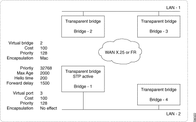 Activation of STP Function
Applicable standards and documents are the following:
| Source | Reference | Status | Title and Contents |
|---|---|---|---|
IAB | RFC768 | Standard | PDU |
IAB | RFC791 | Standard | IP |
IAB | RFC792 | Standard | ICMP |
IAB | RFC793 | Standard | TCP |
IAB | RFC826 | Standard | ARP |
IAB | RFC894 | Standard | IP on Ethernet |
IAB | RFC1058 |
| RIP |
IAB | RFC904 | Standard | EGP |
IAB | RFC919 | Standard | Broadcast Datagrams |
IAB | RFC922 | Standard | Broadcast Datagrams in presence of Subnet |
IAB | RFC950 | Standard | Subnets |
IAB | RFC1009 | Standard | Gateway requirements |
IAB | RFC1042 | Standard | IP on IEEE 802 |
IAB | RFC1356 |
| IP on X.25 |
IAB | RFC1490 |
| IP on Frame relay |
IAB | RFC1548 |
| IP on PPP (not in V12.2) |
IAB | RFC1122 | Standard | Host Requirements: Communications layer |
IAB | RFC1155 | Standard | SMI |
IAB | RFC1157 | Standard | SNMP |
IAB | RFC1213 | Standard | MIB II |
IAB | RFC1027 | Standard | Proxy ARP |
Restrictions
This function provides the interconnection of IP local area networks through X.25, Frame Relay or point-to-point type remote networks. It also allows the declaration of "subnets".
Modeling of IP router
The following diagram explains the modeling of the equipment, showing the different objects of the modeling in relation to the functional architecture. The objects of the model correspond to information necessary for the configuration of the equipment; this includes:
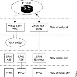 Characteristics of IP Routing Service
Addressing
The equipment performing the IP router function has an IP address per interface. The addresses of class A, B and C are supported. These addresses are furnished on the configuration of the equipment; these values are saved in nonvolatile memory and processed when the equipment configuration is validated.
IP routing principle
Each of the IP networks adjacent to the router (local or remote network) is known by the IP routing function as a "virtual port" having its own IP address. From the destination IP address indicated in the datagram, the IP routing function thus consists in finding the address IP of the next router for the delivery of the datagram as well as the virtual port allowing this router to be reached. This search uses the list of virtual ports and the IP routing table.
The routing operation takes place in a unique addressing plan: the IP addressing plan.
 IP Addressing Plan
List of adjacent networks in router R1
| Dest. network | Access |
|---|---|
130.0.0.0 | direct by WAN VP |
131.1.0.0 | direct by LAN VP |
Routing table in router R1
| Dest. network | Next hop |
|---|---|
132.2.0.0 | 130.0.0.2 via WAN VP |
A second step consists in reaching the IP address of the next router through the virtual port to which it is connected. The IP address to be reached must thus be resolved into an address specific to the transport network used (X.25 address, Ethernet address, etc.): the physical addressing plan is used.
This IP address - physical address resolution is obtained either statically through a configured table or dynamically through an address resolution protocol (ARP).
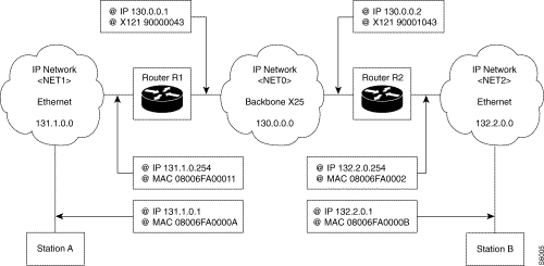 IP Address-Physical Address Resolution
Router R1
Local address resolution: dynamic by ARP
IP address | Ethernet address |
| 131.1.0.1 | 08006FA0000A |
Remote address resolution: static
| IP address | X.121 address |
|---|---|
130.0.0.2 | 90001043 |
Router R2
Local address resolution: dynamic by ARP
| IP address | Ethernet address |
|---|---|
132.2.0.1 | 08006FA0000B |
Remote address resolution: static
| IP address | X.121 address |
|---|---|
130.0.0.1 | 90000043 |
Network interface
The IP routing function allows the management of several LAN or WAN interfaces. Each interface has an IP address; each of these interfaces is associated with a LAN or WAN connection function through Virtual Ports. Several network interfaces may be associated with the same WAN connection function. At the limits, each router or remote subscriber may be interconnected to the IP network by a point-to-point network.
This implementation facility enables the definition of several IP networks on the same WAN via the same connection function.
The network interface provides the following services:
Each virtual port contains the following main information:
These data are configurable in the equipment.
When routing requires the transit of the frame through an output interface whose MTU is smaller than the input MTU, the frame is segmented with the positioning of the identification, flag and fragment offset fields.
Fragmented datagrams are routed normally.
Fragmented datagrams intended for the router are re-assembled. This re-assembly is protected by a timer to prevent the loss of a fragment. Upon the expiration of the timer, and if all the fragments are not received for the frame during recombination, all the fragments in process for this frame are cleared and the corresponding counter of the MIB is incremented.
MTU
The value of the MTU of IP level is modifiable during configuration for each LAN or WAN interface. The permissible values for each interface depend on the specific physical MTU for each type of interface.
| Local network interface | Type of interface | MTU Min. (bytes) | MTU Max. (bytes) |
|---|---|---|---|
| Ethernet | 576 | 1500 |
802.3 | 576 | 1492 | |
802.5 | 576 | 1492 | |
Remote network interface |
|
|
|
| Frame Relay | 576 | 1600 |
X.25 | 576 | 1600 | |
PPP | 576 | 1600 |
Local network interface
Local address resolution (ARP and Proxy ARP)
Routing, limited to IP addressing, determines:
The virtual port enables the determination of the type of interface used to communicate with the remote router. For each IP address of a remote router, the physical address of the remote interface to be reached must be deduced.
This resolution is dynamic for LAN virtual ports using an address resolution protocol (ARP or possibly proxy-ARP in a subnet environment).
A router that does not know how to associate a MAC address with a certain IP address sends a ARP query by polling. Only the LAN station with this IP address will answer so that the equipment can dynamically fill out the table of correspondence for the IP address * Ethernet address.
The router uses the Proxy ARP to enable the station that will not support "subnetting" to determine the MAC address of a station that is not located on the same LAN. In this case, the router responds to an ARP queried the router has the best route to the recipient, with its own MAC address. The station at the origin of the query sends its packets to the router which passes them along to the receiving station.
ARP support
The ARP, as well as the proxy-ARP function, are supported in accordance with RFC 826 and 1027.
ARP manages a cache of 592 inputs with "hashcoding" access on the IP address and life management. The inputs in the process of ARP resolution have a life of 3 minutes; the complete inputs have a life of 20 minutes. Static inputs are permanent inputs of the ARP cache.
Static inputs to the ARP table
It is possible for the user to position static inputs in the ARP table when the equipment is configured.
Static inputs to the ARP table are permanent inputs.
Encapsulation
The modes defined by RFC 1042 (SVC/SNAP) and RFC 894 (PID) are supported. By default, RFC 894 encapsulation is used.
The encapsulation chosen at the level of the virtual port is applied for the frames to be sent and is checked by the received frames. Received frames not corresponding to the type of encapsulation configured are cleared.
The choice of the encapsulation mode used on the local area network is defined during the configuration of the virtual port.
Remote network interface
Interoperability
The interconnection of heterogeneous equipment is obtained by the implementation of standard encapsulation profiles:
The application of these different types of interconnection involves functional blocks defined in the modeling of the equipment.
For LAN protocols, all remote networks are seen by a virtual port of the WAN type associated with a connection manager providing the RFC1356 interface with the WAN switch of the machine.
The support for another type of encapsulation is obtained on the output stack by adapting the type of encapsulation.
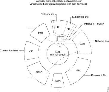
This functional breakdown is justified by the fact that WAN protocols are accessible via an internal WAN switch based on X.25 and offering additional networks services (reliable virtual circuit service, compression, backup/overflow, dynamic WAN routing, etc.). The WAN address of the remote, and hence the connection used to reach the next router, determines the output stack actually used by submitting this address to the internal WAN switch. The output stack may change depending on the evolution of internal routing (backup/overflow, etc.).
Figure 15-18 locates the interfaces for standard encapsulations.
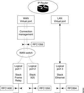 Location of the Interfaces for Standard Encapsulations
Remote address resolution
Routing, limited to the IP addressing plan, determines:
The virtual port makes it possible to determine the type of interface used to communicate with the remote router. For each IP address of a remote router, the physical address of the remote interface to be reached must be deduced.
When accessibility is through a WAN protocol, the IP address of each remote router must be associated with the WAN connection to be used to reach it, by means of the remote address resolution table: IP address => network address (see table of translations).
WAN routing configured in the switch routes the call to the desired output stack identified as a local subscriber.
IP routing table management
The routing table contains all the routes allowing a net or a subnet to be reached. Each route determines the IP address of the "Next Hop" router towards which the datagram is made to progress in order to reach the final destination. These routes are of two types:
Static routes (C44)
The user has the possibility of positioning static inputs in the IP routing table when configuring the equipment.
The information supplied in this table consists of the IP address of the remote network or of the remote station to be reached as well as the IP address of the "Next Hop" router towards which the frame is to be routed and the associated metric value.
The input 0.0.0.0 is reserved for the default router.
These inputs are stored in nonvolatile memory and taken into account when the user enables the configuration.
Dynamic routes
IP routing can take place dynamically by the exchange of information on the routes known to the different routers. These routing information exchanges are made possible by the implementation of a routing protocol (RIP and EGP).
The routing protocols may thus add or remove a route present in the routing table.
The choice of the activation of one or both of these protocols is made by the user during the configuration of the equipment. In addition, the user has protocol configuration facilities for network security and optimization.
EGP implementation facilities (C47):
All the functionalities offered by these protocols are given in the section "IP routing protocols ".
Static inputs to translation table (C42)
When accessibility to a "Next Hop" router is via a WAN protocol, it is possible for the user to configure the WAN network address to be used to access this "Next Hop" router. This network address depends on the WAN protocol used (X.121 address, DLCI No. , etc.).
Construction of IP "subnets"
The user has the possibility of defining IP "subnets". To accomplish this, he must:
The activation of proxy ARP on one of the interfaces is indicated by the user during the configuration of the equipment.
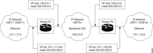
List of adjacent networks in router R1
| Net/Subnet | Mask | Access |
|---|---|---|
130.0.0.0 | 255.255.0.0 | direct via WAN VP |
131.1.17.0 | 255.255.255.0 | direct via LAN VP |
Routing table in router R1
| Dest. net | Subnet mask | Next hop |
|---|---|---|
131.1.18.0 | 255.255.255.0 | 130.0.0.2 via WAN VP |
Principle:
In router R1, during the routing operation on an IP address belonging to subnet 131.1.18.0, the subnet mask defined in the routing table is applied, namely: 255.255.255.0 .
In router R2, during the routing operation on an IP address belonging to subnet 131.1.18.0, the subnet mask associated directly with this subnet is applied, namely: 255.255.255.0.
The ability of the router to take into account the notion of separated subnet allows interconnection, through any IP network <N2>, of an IP subnet belonging to the same IP net <N1>. This facility is authorized because the subnet mask associated with the remote network is taken into account in the routing tables.
The routing protocols used in the equipment (RIP, EGP) do not take into account the notion of subnet mask. The implementation of this type of routing is possible only in the case of static routing.
Example 2: Case of subnet of variable length:
The subnet variables allow the optimization of IP address consumption by assigning a number of different hosts on each subnet. This facility is allowed because the subnet mask associated with the remote network is taken into account in the routing tables.
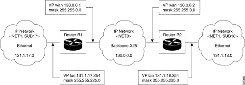 Case of Subnet of Variable Length
Utilization restriction:
Routing protocols implemented on the equipment (RIP, EGP) do not handle the notion of subnet mask (RIP2 or OSPF do handle it). The implementation of this type of routing is possible only in the case of static routing.
ICMP protocol configuration
The implementation of the ICMP protocol is obligatory for IP operation.
In router mode, the user has the possibility of authorizing or inhibiting globally the transmission of ICMP "redirection" packets by the equipment". This facility may be implemented during the configuration of the equipment. It is saved and taken into account when the equipment configuration is validated.
It is possible for the user to request the use of an optimized IP routing allowing improved performance while limiting the checks.
Constraints relative to the use of routing in optimized mode are:
Traffic management in the IP network is facilitated by the identification of the flows carried by the routers and by the application of processing suited to each type of flow. This paragraph hence describes the implementation facilities offered in LANPAC products to approve the quality of service.
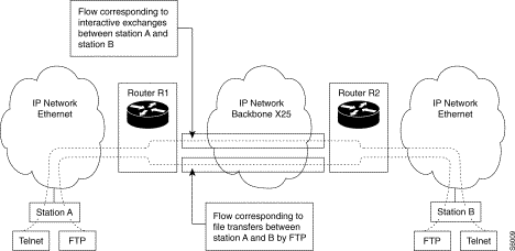
Flow marking (C51)
The user has the possibility of activating flow marking on each virtual port. The associated criteria will be applied to all the IP traffic received on this virtual port.
Each criterion is a set of conditions allowing the association of the frames with each type of flow. The possible conditions (not significant by default) are:
A flow identifier is applied to the criterion and allows it to be associated with any action along:
Important remark:
The application of criteria takes place in increasing order of flow identifiers. The user must consequently ensure the proper order and consistency of the criteria and actions entered.
Traffic separation
Network optimization may lead to different routing for traffic coming from different applications. The router must consequently apply flow recognition criteria to identify such traffic (see preceding section) and must choose the appropriate protocol, bandwidth or priority from among the available communication protocols.
In the case of X.25 and Frame Relay protocols carrying LAN traffic, the separation of traffic is obtained by defining a group of connections towards the same remote, and distributing the identified flows on these connections.
It is possible to configure, by connection, the list of authorized flows. This list is determined by a mask.
During the transmission of a frame on the WAN, the router determines the address of the remote router to be reached based on the destination and encapsulation, and chooses a connection according to the type of flow associated with this frame and the flow mask authorized on this connection.
Remark:
The choice of the connection imposes the throughput characteristics required of the bearer.
On X.25, a connection corresponds to a virtual circuit. The throughput is reserved during the setup of the call by X.25 signaling if the throughput class facility is supported.
ON Frame Relay, a connection corresponds to a DLCI. It is possible to allocate a DLCI with a quality of service by specifying a CIR (Committed Information Rate). The throughput rate is reserved during the setup of the call to the output FR stack by entering the X.25 signaling information.

Filtering on IP network
Flow filtering by virtual port
An IP filter makes it possible to avoid undesired frame routing. Filtering by authorization may be desired, consisting in authorizing only the indicated frames or filtering only by inhibition, consisting in eliminating the received frame.
Filtering by inhibition:
Filtering by authorization:
Flow filtering by connection
The flow/circuit association is obtained by connection. It is thus possible for the user to select the flows carried to any direction and hence disable certain flows towards that direction.
If a flow is not identified on a connection, the frame will be destroyed. It is possible, for example, to authorize some source IP addresses over certain connections and not others (selective filtering by connection)
This function allows the setup of a protection firewall defined by X.25 line.
Priority routing
Priority routing management is a way of directing a flow straight to the output with criteria other than the standard IP routing. Only the criteria are different because priority routing always designates the output by the IP address of the router to be reached ("Next Hop" router).
This facility is a means of implementing a separation of traffic based on the IP logic addressing plan. In particular it is possible to separate the traffic towards two different routers located on the same LAN or toward two different interfaces on the same WAN; for instance, an interface supporting a leased line and an interface supporting a switched line (ISDN).
The implementing of this facility implies the following:
The "Next Hop" router must be accessible by one of the interfaces of the IP router.
Broadcast facility (helpers)
The purpose of this functionality is to allow and control the broadcasting of "IP broadcast" frames on WANs.
On each virtual reception port, the user can mark the flow corresponding to universal IP broadcasts coming from a given application. Such is the case, for example, of "Netbios" broadcasts when the station interrogates the name server accessible via the WAN. This type of configuration is not possible as a standard option because the RFC does not allow the propagation of universal broadcasts.
The action associated with this flow, most often detected at the LAN port (LAN virtual port), is a "helper" or a list of broadcasts to a restricted number of IP addresses (address of remote server(s)). For each address on the broadcast list, the address is substituted for the destination address of the datagram and the frame is routed according to the normal IP routing process.
Filters will be set up with the following criteria:
RIP protocol
The implementation of the RIP protocol, Version 1, by the equipment is in conformity with RFC 1058.
Types of operation: broadcast or filtering
The RIP protocol can send routing information in two ways: broadcast or filtering. The acceptance of RIP information received depends on the type of operation.
Activation modes: quiet or active
The RIP protocol can work under two modes: the quiet or the active mode.
Period of transmissions
Equipment routing information is transmitted periodically.
The transmit period can be configured: its value extends from 30 seconds to 1 hour.
The equipment transmits routing information in RIP-response type messages. These messages contain the routing table of the equipment, with up to 25 inputs per message (the size of the message is limited to 512 bytes).
The periodic aspect of this information transmission makes it possible for an equipment not only to supervise his "neighbors" but also to resist transmission errors.
Response to RIP-request
The equipment responds to RIP-request type messages containing partial or total information requests sent by the other routers.
Implementing the "split horizon"
Loops may appear within the topology of a network.
The rebound effect and the slowness of the convergence in the event of a count up to infinity are undesirable effects encountered during the appearance of loops when a remote vector protocol such as the RIP is implemented.
To solve these problems, the implementation of RIP adopts the technique of the split horizon with poison reverse.
Routing information accessible through an interface are declared inaccessible in RIP-response type messages transmitted on this interface.
Implementing the "triggered update"
The implementation of RIP adopts the triggered update technique for faster solution of rebound and count-to-infinity effects.
The equipment sends an RIP-response type message as soon as the routing table has been modified locally by the change of status of an interface or externally by the reception of new routing information.
Support of "small random timer"
To obviate the synchronization of period information transfers by all the routers of a network, a random timer is added to the transmission period.
This timer is defined as a small random timer whose value extends from 1 to 5 seconds.
Minimum compatibility with RIP version 2
The RIP protocol version 1 uses the inputs of RIP2-response type messages for which the fields specific to version 2 have been left at zero.
Such inputs are in fact altogether utilizable by equipment using RIP version 1 since they contain all the data enabling their interpretation and since they add no new notion in relation to the first version of the protocol.
Redistribution of static information by RIP
See paragraph dealing with redistribution (§ 20.6.5.3.2.).
RIP redistribution of information learnt by EGP
See paragraph dealing with redistribution (§ 20.6.5.3.3.).
EGP protocol
The implementation of the EGP protocol version 2 by the equipment is in conformity with RFC 904.
Activation
When the EGP protocol is activated, it is furnished the list of neighboring equipment.
This list contains the IP addresses of routers with which the equipment establishes EGP neighboring and with which it exchanges routing information.
Acquisition of neighboring
The acquisition of neighboring constitutes the first phase of the EGP protocol. This mechanism is implemented so that two adjacent routers agree to become neighbors. This agreement takes place before any exchange of routing information.
On start-up, the equipment tries to establish EGP neighboring with each of the routers declared in the table of neighbors. At the same time, the equipment accepts neighboring only with a declared neighbor.
During this phase, the equipment negotiates so two timers, namely the hello timer and the poll timer, with its counterpart. The first is used during the neighboring accessibility phase while the second is used during the network accessibility phase.
The equipment proposes, during negotiation, the values of 30 seconds and 120 seconds for each of these timers.
Neighboring accessibility
Neighboring accessibility constitutes the second phase of the EGP protocol. This mechanism is implemented so that the equipment is sure that neighboring with a counterpart router is indeed still established.
After establishing neighboring and as long as this neighboring remains established, the equipment periodically transmits EGP-Hello type messages to the neighboring router concerned. The equipment waits, in return, for the neighboring router to reply by means of an EGP-Ihu type message. As long as the neighbor replies, neighboring is considered to remain established. The neighbor no longer replies, the neighboring is considered to be interrupted.
EGP-Hello type messages are transmitted periodically. The transmission period is defined by the value of the hello timer whose default value is 30 seconds and whose "permissible value" range extends from 30 seconds to 900 seconds.
The value of the hello timer is not configurable.
Network accessibility
Network accessibility constitutes the third phase of the EGP protocol. This mechanism is implemented so that the equipment learns the routing information known to the neighboring routers with which it has established neighboring.
After establishing neighboring and as long as this neighboring remains established, the equipment periodically sends EGP-Poll type messages to the neighboring equipment concerned.
The equipment waits for the neighboring router to reply by means of an EGP-Info type message containing all the known routing information of the neighbor.
EGP-Poll type messages are transmitted periodically. The transmission period is defined by the value of the poll timer, whose default value is 120 seconds, and whose range of permissible values extends from 120 seconds to 3000 seconds.
The value of the poll timer cannot be configured.
Characteristics of information redistribution
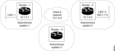
Static routes may be redistributed towards neighboring routers through RIP or EGP routing protocols. Neighboring routers can thus benefit form the static configuration of the equipment. Also, questions relative to security may be such that the administrator does not wish to give other routers visibility to this static information.
Thus, static routes may or not be redistributed.
Redistribution of static routes by RIP
The redistribution of static routes by the RIP protocol may be enabled or disabled when the equipment is configured.
Static routes are redistributed to all the routers defined in the filtering list (case of transmission in filtering mode) or broadcast over all the active interfaces.
An input of an RIP-Response type message corresponding to redistributed static routing information is not distinguished from other inputs. The metric value used for this input is that supplied during the declaration of the static route.
Redistribution of static routes by EGP
The redistribution of static routes by the EGP protocol can be enabled or disabled when the equipment is configured.
Static routes are redistributed to all the neighboring routers with which the equipment has established neighboring.
An input of an EGP-Info type message corresponding to redistributed static routing information is not distinguished from the other inputs. However, the metric value used for this input is no longer that supplied during the declaration of the static route.
A new value is assigned to it: this value is furnished to the configuration and is common to all the routing information redistributed by EGP (static routes or routes learnt by RIP). This redistribution method has a default value of 128; the range of permissible values extends from 1 to 255.
Redistribution of EGP protocol by RIP
The redistribution by RIP of the routing information learnt by the EGP protocol can be enabled or disabled when the equipment is configured.
Only information coming from certain Autonomous Systems (AS) are redistributed. These ASs are indicated in the table of ASs redistributed by RIP.
These information is then redistributed to all the routers defined in the filtering list (case of transmission in filtering mode) or even by broadcasting on all active interfaces.
An input of the RIP-Response type message corresponding to routing information learnt by EGP and redistributed by RIP is not to be distinguished from the other inputs. However, the metric value used for this input is no longer associated with the EGP protocol.
A new value is assigned to it; this value is furnished to the configuration and is common to all the routing information learnt by the EGP protocol and coming form a special AS: all this information from an AS is assigned the same metric value.
A redistribution metric type is thus formed during configuration for each AS EGP redistributed by RIP. This metric type has no default value; the range of permissible values extends from 1 to 15.
Redistribution of RIP protocol by EGP
Redistribution by the EGP protocol of routing information learnt by the RIP protocol may be enabled or disabled when the equipment is configured.
This information is redistributed to all the neighboring routers with which the equipment has established neighboring.
An input of an EGP-Info type message corresponding to routing information learnt by RIP and redistributed by EGP is not distinguished from the other inputs. However, the metric type used for this input is no longer associated with the RIP protocol.
A new value is requested of it; this value is supplied to the configuration and is common to all the routing information redistributed by EGP (static routes or routes learnt by RIP). This redistribution metric value is 128; the range of permissible values extends from 1 to 255.
Route management
Several routes may exist for a given recipient. A notion of preference relative to the way a route has been learnt allows the determination of the route which is actually used by the router.
The order of preferences is indicated below.
The active route towards a destination is the one that has the smallest preference. For example, a static route (furnished during configuration) is always preferred to a route learnt by RIP or by EGP.
| Type of route | Knowledge | Preference |
|---|---|---|
Directly accessible network | defined during configuration | 0 |
Redirected route | learnt by the ICMP protocol | 30 |
Static route | defined during configuration | 60 |
RIP route | learnt by the RIP protocol | 100 |
Point-to-point route | defined during configuration | 110 |
Route via interface down | detected during scanning | 120 |
EGP route | learnt by EGP protocol | 200 |
For information |
|
|
OSPF route | learnt by OSPF protocol | 10 |
Route IS-IS level 1 | learnt by IS-IS protocol | 15 |
Route IS-IS level 2 | learnt by IS-IS protocol | 18 |
HELLO routes | learnt by HELLO protocol | 90 |
AS OSPF external routes | learnt by OSPF protocol | 150 |
BGP routes | learnt by BGP protocol | 170 |
A block diagram of the configuration elements in relation to the functional architecture is given below:
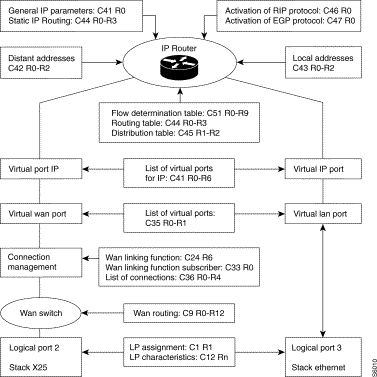
General activation of the DOD IP router - C41R0
Table of IP virtual ports - C41 R1 to 5
Supplementary table for local IP virtual ports - C41 R6
IP static routing table - C44 R0 to 3
Local address resolution table - C43 R0 to 2
Flow determination table - C51
Flow routing table - C51
Broadcast help table - C51
The main configuration elements required for the environment of the IP router function are:
| Class No. | Class name | Equipment 1 | Equipment 2 | ||
|---|---|---|---|---|---|
C44 | Static routes | Dest Ip 194.107.114.0 | Next Hop 194.1.1.2 | Dest Ip 193.107.114.0 | Next Hop 194.1.1.1 |
C42 | IP/X.121 Corres. | 90002093 | 194.1.1.2 | 90001093 | 194.1.1.1 |
C41 | IP Interfaces | Ethernet 193.107.114.41 | Distant 194.1.1.1 | Ethernet 194.107.114.42 | Distant 1094.1.1.2 |
C36 | Connection table |
| VP = 29000 20 93 |
| VP = 29000 20 93 |
C35 | Table of VP | local VP = 3 | distant VP =2 | local VP = 3 | distant VP =2 |
C33 | Table of modules | Local subscriber 93 |
| Local subscriber 93 |
|
C1R1 | Line | Line 3 = Ethernet | Line 1 = X.25 DCE | Line 3 = Ethernet | Line 2 = X.25 DTE |
Principle
| C36R0 | ||
|---|---|---|
P0 | 1,3,0,0 |
|
P1 | 1,2,0,0 |
|
| C36R1 |
|
|
P0 | 1,3,3,255 |
|
| C36R0 |
|
|
P0 | 90002043 | Aimed point |
| C36R2 |
|
|
P0 | 2,255,255,255 | First module VP |
| C36R3 |
|
|
P0 | 1,3,0,255 | Multiplexed type, datagram Mode, Without grouping |
| C36R4 |
|
|
P0 | 1,10,10,255 | Valid status, inactivity timer, call retransmission timer |
| General parameters of Bridge: |
|
|
| C37R0 |
|
|
P0 | 0 | Inactive transparent bridge |
| Transparent bridge parameters: |
|
|
| C38 (Unnecessary) |
|
|
| General parameters of IP: |
|
|
| C41R0 |
|
|
P0 | 1 | Activation of router |
P1 | 0 | Normal mode |
P2 | 0 | No ICMP redirect |
P3 | 0 | No routing source |
| C41R1 |
|
|
P0 | 1,3,0,255 | Valid status, Ethernet VP, no Proxy ARP |
P1 | 1,2,0,255 | Valid status, remote VP, no Proxy ARP |
| C41R2 |
|
|
P0 | 193,107,114,41 | IP address of Ethernet interface |
P1 | 194,1,1,1 | IP address of Remote interface |
C41R3 |
|
|
P0 | 255,255,255,0 | Ethernet interface network mask |
P1 | 255,255,255,0 | Remote interface network mask |
| C41R4 |
|
|
P0 | 1500 | Ethernet interface MTU |
P1 | 1500 | Remote interface MTU |
| C41R6 |
|
|
P0 | 1,3,0,255 | Valid status, local VP, V2 Ethernet Encapsulation |
|
|
|
| IP/X.121 correspondence table: |
|
|
| C42R0 |
|
|
P0 | 194,1,1,2 | Next router interface IP address |
| C42R1 |
|
|
P0 | 90002043 | Next router aimed point |
| C42R2 |
|
|
P0 | 1 | Valid status |
| Remote network to be reached: |
|
|
| C44R0 |
|
|
P0 | 194,107,114,0 | Remote network to be reached |
| C44R2 |
|
|
P0 | 1,1 | Valid status, metric value 1 |
| C44R3 |
|
|
P0 | 194,1,1,2 | Next router IP address |
| RIP parameters |
|
|
| C46R0 |
|
|
P0 | 0 | No active RIP |
| EGP parameters: |
|
|
| C47R0 |
|
|
P0 | 0 | No active EGP |
Static routing
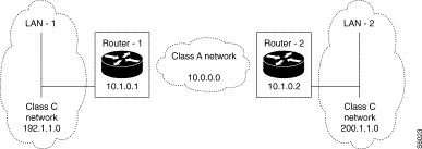 Static Routing
Purpose:
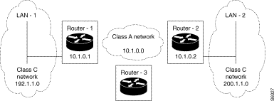
To set up end-to-end static routing between the two end LAN networks, LAN-1 and LAN-2. In the example, Router-1 has visibility over LAN-2 through Router-2. Similarly, Router-2 has visibility over LAN-1 through Router-1.
Configuration:
The accessibility of LAN-2 (or LAN-1) by Router-1 (or Router-2) is furnished during the configuration of Router-1 (or Router-2) in the form of a static route whose next hop consists of Router-2 (or Router-1). No routing protocol is activated since routing is purely static.
| Configuration of Router-1: | ||
|---|---|---|
| Routing table |
|
|
C44-R0-P0 = 200, 1, 1, 0 |
| LAN-2 network address |
C44-R2-P0 = 1, 1, 2 | The input is valid; the type of route is classical; the metric value is 2 |
|
| C44-R3-P0 = 10, 1, 0, 2 | LAN-2 is accessible via Router 2 |
|
| RIP parameters |
|
|
C46-R0-P0 = 0 | The RIP protocol is deactivated; routing is purely static |
|
| EGP parameters |
|
|
C47-R0-P0 = 0 | The EGP protocol is deactivated; routing is purely static |
|
| Configuration of Router-2: |
|
|
| Routing table |
|
|
C44-R0-P0 = 192, 1, 1, 0 | LAN-1 network address |
|
C44-R2-P0 = 1, 1, 2 | The input is valid; the type of route is classical; the metric value is 2. |
|
C44-R3-P0 = 10, 1, 0, 1 | LAN-1 is accessible via Router 1 |
|
| RIP parameters |
|
|
C46-R0-P0 = 0 | The RIP protocol is deactivated; routing is purely static |
|
| EGP parameters |
|
|
C47-R0-P0 = 0 | The EGP protocol is deactivated; routing is purely static |
|
|
|
|
 RIP Active in BroadCast Mode
Purpose:
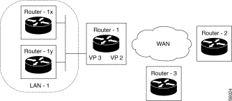
Activate the RIP protocol in broadcast mode on all the interfaces of the equipment. In the example, Router-1 has two interfaces; one is linked to the LAN network, the other to the WAN transport network. The LAN interface is associated with VP 3 and the WAN interface with VP 2.
Configuration:
The RIP protocol is configured in active mode. The broadcast type is chosen. VP 2 and 3 are placed in the table of RIP interfaces.
| Configuration of Router-1: | |
|---|---|
| RIP parameters |
|
C46-R0-P0 = 1 | The RIP protocol is configured in active mode |
C46-R0-P1 = 0 | The broadcast type is chosen |
C46-R0-P2 = 0 | The redistribution of static routes is not enabled |
C46-R0-P3 = 0 | The redistribution of EGP information is not enabled |
C46-R0-P4 = 30 | The period of the transmissions is set at 30 seconds |
| List of RIP interfaces |
|
C46-R1-P0 = 1, 2, 1, 255 | RIP is enabled on VP 2 and hence on the WAN interface |
C46-R1-P0 = 1, 3, 1, 255 | RIP is enabled on VP 3 and hence on the LAN interface |
List of filters
The list of filters is empty; it is in any case not used because the broadcast type is chosen.
Information on redistribution of EGP by RIP
Not used because redistribution is not enabled.
 RIP Active in Filtering Mode
Purpose:
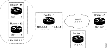
Activate the RIP protocol in filtering mode and obtain the exchange of routing information by RIP with two equipments only; one placed on the LAN, the other on the WAN. In our example, Router-1 sends RIP-Response type messages only to the Router-12 and Router-2 equipment (IP monocast transmission). Likewise, it accepts messages of this type only coming from these two equipments; all other messages are ignored.
Configuration:
The RIP protocol is configured in active mode. The filtering type is chosen. The IP addresses of the Router-12 and Router-2 equipments are placed in the list of RIP filters.
Configuration of Router-1:
RIP parameters
C46-R0-P0 = 1 The RIP protocol is configured in active mode
C46-R0-P1 = 1 The filtering type is chosen
C46-R0-P2 = 0 The redistribution of static routes is not enabled
C46-R0-P3 = 0 The redistribution of EGP information is not enabled
C46-R0-P4 = 30 The transmission period is set at 30 seconds
List of RIP interfaces
The list of interfaces is empty; it would in any case not be used because the filtering type has been chosen.
List of filters
C46-R2-P0 = 10, 1, 0, 2 Filter (neighbor) RIP 10.1.0.2 on WAN side
C46-R3-P0 = 1
C46-R2-P1 = 192,1,1,12 Filter (neighbor) RIP 192.1.1.12 on LAN side
C46-R3-P1 = 1
Information on redistribution of EGP by RIP
Not used because redistribution is not enabled.
Purpose:
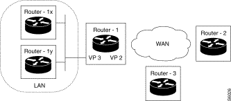
Activate the RIP protocol in quiet mode; mode in which the equipment does not send any routing information, simply listens to RIP traffic and modifies the routing tables accordingly. In the example, on start-up, Router-1 transmits an RIP-request type message requesting the active equipments to send it their routing information immediately. Then, Router-1 listens to all the RIP traffic on the two networks directly accessible: LAN network through VP 3 and WAN network through VP 2.
Configuration:
The RIP protocol is configured in quiet mode. The broadcast type is chosen. VP 2 and 3 are placed in the table of RIP interfaces. The type of broadcast makes it possible to determine the type of RIP information source accepted by the equipment: the broadcast type indicates that the equipment listens to all the RIP traffic, the filtering type indicates that the equipment listens only to RIP traffic transmitted by the equipment of the list of filters.
Configuration of Router-1:
| RIP parameters | |
|---|---|
C46-R0-P0 = 1 | The RIP protocol is configured in quiet mode |
C46-R0-P1 = 1 | The broadcast type is chosen |
C46-R0-P2 = 0 | Redistribution of static routes is not enabled |
C46-R0-P3 = 0 | Redistribution of EGP information is not enabled |
C46-R0-P4 = 30 | The transmission period is set at 30 seconds |
| List of RIP interfaces |
|
C46-R1-P0 = 1, 2, 1, 255 | RIP is enabled (for listening) on VP 2 and hence on the WAN interface |
C46-R1-P0 = 1, 3, 1, 255 | RIP is enabled (for listening) on VP 3 and hence on the LAN interface |
| List of filters |
|
The list of filters is empty; it is in any case not used because the broadcast type is chosen | |
| Information on redistribution of EGP by RIP | |
Not used because redistribution is not enabled. | |
Purpose
Activate the RIP protocol in active mode and allow the redistribution of static routes to certain equipment (filtering type distribution). In the example, Router-3 has static accessibility information from LAN-2 through Router-2. Router-3 redistributes this accessibility information via RIP to Router-1, enabling it in turn to access LAN-2 through Router-2.
Configuration:
The RIP protocol is configured in active mode. The chosen type of distribution is filtering. Only the address of Router-1 is placed in the filtering list. Accessibility information from LAN-2 is placed in the routing table. Redistribution of static information by RIP is enabled..
Configuration of Router-3:
| Routing table | |
|---|---|
C44-R0-P0 = 200, 1, 1, 0 | LAN-2 network address |
C44-R1-P0 = 255, 255, 255, 0 | LAN-2 is not subnetted |
C44-R2-P0 = 1, 1, 2 | The input is valid; the type of route is classical; the metric value is. |
C44-R3-P0 = 10, 1, 0, 2 | LAN-2 is accessible via Router 2 |
| RIP parameters |
|
C46-R0-P0 = 1 | The RIP protocol is configured in active mode |
C46-R0-P1 = 1 | The chosen type of distribution is filtering |
C46-R0-P2 = 1 | Static route redistribution is enabled. |
C46-R0-P3 = 0 | The redistribution of EGP information is not enabled |
C46-R0-P4 = 30 | The transmission period is set at 30 seconds. |
List of RIP interfaces
The list of interfaces is empty; it would in any case not be used because the chosen distribution is filtering.
List of filters
C46-R2-P0 = 10, 1, 0, 1 Filter (neighbor) RIP 10.1.0.1 on WAN side
C46-R3-P0 = 1
Information on redistribution of EGP by RIP
Not used because redistribution is not enabled.
Purpose:
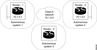
Activate the EGP protocol and enable the equipment to exchange routing information through the EGP protocol with two equipments accessible on the WAN side. In the example, Router-3 is configured with two EGP neighbors, namely the equipment Router-1 and Router-2.
Configuration:
The EGP protocol is activated on Router-3 belonging to AS 3. The IP addresses of Router-1 and Router-2 equipment are placed in the table of EGP neighbors. This equipment belongs respectively to AS 1 and 2.
Configuration of Router-3:
| EGP parameters | |
|---|---|
C47-R0-P0 = 1 | EGP enabled |
C47-R0-P1 = 3 | Local AS number 3 |
C47-R0-P2 = 0 | Redistribution static routes by EGP: no |
C47-R0-P3 = 0 | Redistribution RIP information by EGP: no |
C47-R0-P4 = 1 | Redistribution metric value: not used |
| Table of EGP neighbors | |
|---|---|
C47-R1-P0 = 10, 1, 0, 1 | IP address of neighbor 10.1.0.2 |
C47-R2-P0 = 1 | AS number of neighbor: 1 |
C47-R3-P0 = 1 | Input status: valid |
C47-R1-P1 = 10, 1, 0, 2 | IP address of neighbor 10.1.0.2 |
C47-R2-P1 = 2 | AS number of neighbor: 2 |
C47-R3-P1 = 1 | Input status: valid |
|
|

Purpose:
Activate the EGP protocol and allow the redistribution of static routes to EGP neighbors. In our example, Router-3 has accessibility information from the LAN-2 network through Router-2. Moreover, Router-3 exchanges EGP information with Router-1. Router-3 redistributes by EGP to Router-1 the accessibility information from LAN-2 enabling Router-1 to access LAN-2 through Router-2.
Configuration:
The EGP protocol is activated. The address of Router-1 is placed in the table of EGP neighbors. Accessibility information is placed in the routing table. Redistribution of static routes by EGP is activated.
| Configuration of Router-3: | |
|---|---|
| Routing table |
|
C44-R0-P0 = 200, 1, 1, 0 | LAN-2 network address |
C44-R1-P0 = 255, 255, 255, 0 | LAN-2 is not subnetted |
C44-R2-P0 = 1, 1, 2 | The input is valid; the type of route is classical; the metric value is 2 |
C44-R3-P0 = 10, 1, 0, 2 | LAN-2 is accessible via Router 2 |
| EGP parameters |
|
C47-R0-P0 = 1 | EGP activated |
C47-R0-P1 = 3 | Local AS number 3 |
C47-R0-P2 = 1 | Redistribution of static routes by EGP: yes |
C47-R0-P3 = 0 | Redistribution of RIP info by EGP: no |
C47-R0-P4 = 128 | Redistribution metric value: 128 |
| Table of EGP neighbors |
|
C47-R1-P0 = 10, 1, 0, 1 | IP address of neighbor 10.1.0.1 |
C47-R2-P0 = 1 | AS number of neighbor: 1 |
C47-R3-P0 = 1 | Input status: valid |
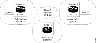
Purpose:
Activate the RIP and EGP protocols simultaneously. Exchange EGP routing information with a first equipment. Exchange RIP routing information with a second equipment in filtering mode. Redistribute through RIP the information learnt by EGP. In the example, Router-3 exchanges EGP (or RIP) routing information with Router-2 (or Router-1) and redistributes to Router-1 the information learnt by Router-2.
Configuration:
The RIP (filtering) and EGP protocols are activated. The address of Router-1 is placed in the table of RIP filters. The address of Router-2 is placed in the table of EGP neighbors. Redistribution of EGP par RIP is enabled.
| Configuration of Router-3: | |
|---|---|
| RIP parameters |
|
C46-R0-P0 = 1 | The RIP protocol is configured in active mode |
C46-R0-P1 = 1 | The type of distribution chosen is filtering |
C46-R0-P2 = 0 | Redistribution of the static routes is not activated |
C46-R0-P3 = 1 | Redistribution of EGP information is activated |
C46-R0-P4 = 30 | The transmission period is set at 30 seconds |
| List of RIP interfaces |
|
The list of interfaces is empty; it is not used in any case because the chosen distribution is of the filtering type. | |
| List of filters |
|
C46-R2-P0 = 10, 1, 0, 1 | Filter (neighbor) RIP 10.1.0.1 on WAN side |
C46-R3-P0 = 1 |
|
| Table of EGP ASs to be redistributed by RIP | |
C46-R4-P0 = 1, 1, 2 | The redistributed AS is the one to which Router-2 belongs: AS 2 |
| EGP parameters |
|
C47-R0-P0 = 1 | EGP activated |
C47-R0-P1 = 3 | Local AS number 3 |
C47-R0-P2 = 0 | Redistribution of static routes by EGP: no |
C47-R0-P3 = 0 | Redistribution of RIP information by EGP: no |
C47-R0-P4 = 1 | Redistribution metric value: not used |
| Table of EGP neighbors |
|
C47-R1-P0 = 10, 1, 0, 2 | IP address of neighbor 10.1.0.2 |
C47-R2-P0 = 2 | AS number of neighbor: 2 |
C47-R3-P0 = 1 | Input status: valid |

Purpose:
Activate the RIP and EGP protocols simultaneously. Exchange EGP routing information with a first equipment. Exchange RIP routing information with a second equipment in filtering mode. Redistribute through EGP the information learnt by RIP. In our example, Router-3 exchanges EGP (or RIP) routing information with Router-2 (or Router-1) and redistributes to Router-1 the information learnt by Router-2.
Configuration:
The RIP (filtering) and EGP protocols are activated. The address of Router-1 is placed in the table of RIP filters. The address of Router-2 is placed in the table of EGP neighbors. Redistribution of EGP par RIP is enabled.
Configuration of Router-3:
| RIP parameters | |
|---|---|
C46-R0-P0 = 1 | The RIP protocol is configured in active mode |
C46-R0-P1 = 1 | The type of distribution chosen is filtering |
C46-R0-P2 = 0 | Redistribution of the static routes is not activated |
C46-R0-P3 = 0 | Redistribution of EGP information is activated |
C46-R0-P4 = 30 | The transmission period is set at 30 seconds |
| List of RIP interfaces |
|
The list of interfaces is empty; it is not used in any case because the chosen distribution is of the filtering type. | |
| List of filters |
|
C46-R2-P0 = 10, 1, 0, 1 | Filter (neighbor) RIP 10.1.0.1 on WAN side |
C46-R3-P0 = 1 |
|
| Table of EGP ASs to be redistributed by RIP | |
Not used because redistribution is not enabled | |
| EGP parameters |
|
C47-R0-P0 = 1 | EGP activated |
C47-R0-P1 = 3 | Local AS number 3 |
C47-R0-P2 = 0 | Redistribution of static routes by EGP: no |
C47-R0-P3 = 1 | Redistribution of RIP information by EGP: yes |
C47-R0-P4 = 1 | Redistribution metric value: not used |
| Table of EGP neighbors |
|
C47-R1-P0 = 10, 1, 0, 2 | IP address of neighbor 10.1.0.2 |
C47-R2-P0 = 2 | AS number of neighbor: 2 |
C47-R3-P0 = 1 | Input status: valid |
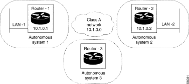
Purpose:
Assign a default route used by the equipment to route a PDU whose destination network is not known to the equipment. In the example, Router-1 routes all the traffic not intended for LAN-1 to Router-2 which routes all the traffic not intended for LAN-2 to Router-3 which routes all the traffic not intended for LAN-3 to Router-3: a default routing loop is thus formed between the three equipments..
Configuration:
The default route 0.0.0.0 is placed in the routing table of each of the Routers 1, 2 and 3, with Router-2, 3 and 1 as associated next hop equipment.
| Configuration of Router-1: | |
|---|---|
C44-R0-P0 = 0, 0, 0, 0 | Default route via Router-10.1.0.2 |
C44-R1-P0 = 0, 0, 0, 0 |
|
C44-R2-P0 = 1, 1, 2, 255 |
|
C44-R3-P0 = 10, 1, 0, 2 |
|
| Configuration of Router-2: |
|
C44-R0-P0 = 0, 0, 0, 0 | Default route via Router-10.1.0.3 |
C44-R1-P0 = 0, 0, 0, 0 |
|
C44-R2-P0 = 1, 1, 2, 255 |
|
C44-R3-P0 = 10, 1, 0, 3 |
|
| Configuration of Router-3: |
|
C44-R0-P0 = 0, 0, 0, 0 | Default route via Router-10.1.0.1 |
C44-R1-P0 = 0, 0, 0, 0 |
|
C44-R2-P0 = 1, 1, 2, 255 |
|
C44-R3-P0 = 10, 1, 0, 1 |
|
The IPX router provides the interconnection of IPX local networks through remote networks of the frame relay, X.25, ISDN or point-to-point type.
IPX routing is carried out on the basis of several sources of information:
Figure 15-36 shows a typical network architecture using the IPX router. Each IPX network has its own IPX address. All PCs connected to the IPX router on the central site have the network address IPX 1. Likewise, all PCs connected to the IPX router in the remote office have the address IPX 10. The WAN link between the two routers has the address IPX DD01.

The IPX router uses the circuit term to name the links, whether LAN or WAN. Thus, the WAN link, or each of the two LANs represented in Figure 15-36, are circuits.
Internally, each IPX circuit is in a direct connection with an interface called a virtual port.
The following diagram shows the flow of data in the equipment. The notions of virtual port, logical port and physical port are used in this diagram. They have the following meaning:
Virtual port
The virtual port enables the IPX router to access the networks, whether LAN or WAN, homogeneously. WAN virtual ports use the switching services of the equipment and thus allows such services as: overflow, backup, compression.
Logical port
A logical port is a communication interface between two nodes and supporting a given protocol.
Physical port
A physical port is the physical connection interface.
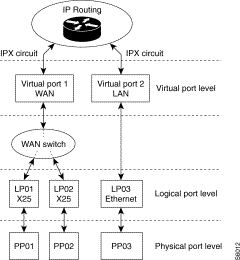 Modeling of IPX Router
General parameters of the router
Name of router
The system can receive a name of 48 characters. This name is used by the SAP service of the router to announce its routing service on the circuits connected directly to it.
By default, the router has no configured name.
Activation of IPX router
The IPX router can be put into service or out of service by simply modifying this activation parameter.
Circuits
Each circuit contains the following information:
The current version of the IPX router supports the definition of 100 circuits.
Configuring a virtual port
As we saw earlier, each circuit is linked directly to a virtual port. The virtual port allows the "masking" of the communication medium used for the interconnection. It thus presents a homogeneous network interface to the IPX routing function.
Frame encapsulation.
Two types of virtual port (VP) are nevertheless to be considered:
Configuration of LAN VP
Each LAN VP contains the following information:
There are 24 LAN VPs available for configuration.
Configuring a WAN VP
Each WAN VP contains the following information:
There are 100 WAN VPs available for configuration.
The respective structures of the headers for the four types of encapsulation are given below:
| 6-bytes | 6-bytes | 2-bytes | 1 byte | 1 byte | 1 octet | n bytes |
|---|---|---|---|---|---|---|
Destinationaddress | Sourceaddress | Length < 1500 | DSAP 0xE0 | SSAP 0xE0 | Control 0x03 | Data |
|
|
| --- 802.2 SVC header-- |
| ||
| 6-bytes | 6-bytes | 2-bytes | 1 byte | 1 byte | 1 byte | 3 bytes | 2 bytes | n bytes |
|---|---|---|---|---|---|---|---|---|
Destinationaddress | Sourceaddress | Length < 1500 | DSAP 0xAA | SSAP 0xAA | Control 0x03 | Protocol identifier 0x0000008137 | Type | Data |
|
| 0x8137 |
| |||||
|
|
| --------------------------- SNAP header -------------------- | |||||
| 6-bytes | 6-bytes | 2-bytes | n bytes |
|---|---|---|---|
Destination address | Source address | Length | Data |
< 1500
Ethernet II
6-bytes 6-bytes 2-bytes n bytes
Destination address Source address Type Data
0x8137
IPX routing
Routing table
The routing table contains all the known routes of the IPX router. Each route determines the IPX address of the "Next Hop" router towards which the datagram progresses to reach the final destination. These routes may be of two types:
Static routes configurable in the equipment
Dynamic routes learnt by the RIP routing protocol
The IPX routing table is composed of the following elements:
Network address Number of hops to reach the network Number of ticks to reach the network Circuit MAC address of Next-hop router
Protocol Life
00000001 1 2 1 static
00000002 1 2 2 rip 0
FFED0038 2 3 3 00001B029927 rip 1
This routing table can be consulted through an SNMP manager via the "Destination Table" of the Forwarding group.
Operating modes for routing
The following operating modes are available:
Static routes are taken into account even when RIP is in service. A static route may be replaced by a route learnt by RIP if this route costs less than the static route. In the present version, if the route learnt by RIP should disappear, the static route does not appear.
The RIP may or not be activated. If RIP is "off", the router operates in static routing mode.
In addition, for better interconnection flexibility, the RIP protocol may or not be circuit-activated (see paragraph on RIP).
General routing parameters
Number of hops authorized
The default number of hops authorized for an IPX frame is 16. It may be increased to 256.
Number of routes authorized in parallel
The IPX router offers the possibility of managing several paths of the same cost to the same destination in parallel. The number of paths authorized in parallel is up to 32. By default, it is 1. During the routing operation, if several paths exist, IPX datagrams are shared equally on the different parallel paths.
Static routes
The required information (in accordance with the IPX/RIP MIB) consist of:
The number of static inputs available is 64.
IPX filtering
IPX filtering allows the prohibition or authorization of IPX datagrams having a particular address. This address may be:
In the present version, there is no possibility of obtaining a logical combination of filters: for example, to filter on the source network address and on the destination network address.
IPX filters are to be defined per circuit. This requires the following:
There are 64 IPX filters available.
For example, to filter IPX "serialization" datagrams periodically transmitted by each NetWare 4.x server, the equipment administrator must program a filter on the WAN circuits composed of:
Routing of broadcast packets
Two types of broadcasts are to be considered:
IPX routing, like any routing protocol, does not route packets in broadcasting.
Nevertheless, the software offers the possibility of enabling or disabling the broadcasting of IPX type-20 packets. This enabling is carried out at two levels:
There is no mechanism for broadcasts either than those of type 20.
In case of inactivity, the NCP session service of the NetWare servers transmits session control (keepalive) frames about every 5 minutes. The client station must, if it wants the session to remain open, acknowledge this frame. In the case of an interconnection by a telephone link that the router cuts off upon inactivity, and opens upon activity (in a manner transparent to the user), it is desirable for the session to remain open and for the user not to must bear the cost of telephone calls every five minutes.
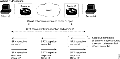 WatchDog NCP Timer Spoofing
For this purpose, on a session control (keepalive) packet that is to come out on a circuit in the non-connected state, the IPX router simulates the remote station and returns the required acknowledgment to the NetWare server.
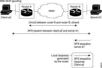 NCP Spoofing
The NCP spoofing feature can be activated on all or part of the circuits. Nevertheless, this feature is not operational on a LAN type circuit.
Protocol
The implementation of the RIP protocol version 1 by the equipment is in conformity with RFC 1058.
Parameterization of RIP
Enabling RIP on a circuit
The user can enable or disable the RIP on each circuit independently. By default, the RIP is not enabled.
"RIP Update" packet announcement time
The information broadcast in the "RIP update" packets may become significant in the case of complex networks. In order to optimize the use of the available bandwidth on the circuit, it is possible to modify the RIP table transmission period. This period is specific to each IPX circuit and may take on a value ranging from 0 to 65535s.
The default announcement time value is 60 seconds.
If the "RIP Update" packet announcement time is equal to 0, this means that "RIP Update" packets are no longer sent by the router on this circuit. This operating mode may be interesting in the case of an interconnection via a telephone link that the router cuts off upon inactivity and opens upon activity (in a manner transparent to the user).
Aging of routing information
The announcement time is used in connection with the aging of routing information. An entry of the routing table learnt by RIP, not refreshed after the time-out of the timer is withdrawn from this table. The value of the time-out timer is by default 4 times the announcement time.
Generated RIP packet size
The size of generated RIP packets is circuit-configurable.
RIP filtering
Two types of filtering on the RIP level are offered:
Input filtering
Input filtering is applied to RIP datagrams of all the circuits of the router. The purpose of this filtering is to inhibit route access to the routing table.
As a first approach, it allows a reduction in the number of inputs to each table. By extension, it reduces the number of RIP or SAP packets propagated by the router. The purpose of this filtering is to prevent access of a route, a group of routes, a service or a group of service to all the circuits of the router.
 Input Filtering
Output filtering
RIP output filtering is obtained by circuit. It is applied to RIP datagrams of the circuit in question. The purpose of this filtering is to inhibit broadcasting on a route circuit. It is applied during the generation of RIP packets and allows the selective restriction of router access by circuit.
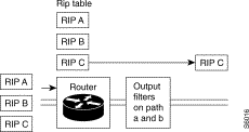 Output Filtering
SAP protocol
SAP is used to locate services in the network (for example, printers, servers, etc.). The IPX router maintains a table of services and periodically rebroadcasts the information contained in this table.
Table of services
The table of services is updated by the SAP.
The table of services contains the following information:
Name of service Address of server (network-node-socket) Type of service Number of hops Circuit Life
FSERVER1 00000123-00001B029888-0451 4 1 1 0
GSERVER3 00000002-00001B0349B2-0451 6 2 3 1
PSERVER2 FEED0038-00001B023458-0451 2 3 12 2
The table of services can be displayed by an SNMP manager via the "Services Table" of the Services group.
The user may enable or disable the SAP service in the router function.
Static services
The user can position static inputs in the table of services of the equipment.
The information to be supplied is as follows:
It is to be noted that the information couple: circuit identifier, server address, may serve to enrich the IPX routing table.
The number of static inputs saved by the equipment is limited to 64.
SAP parameterization
Circuit activation of SAP
The user may enable or disable SAP on each circuit independently.
Periodic SAP Update packet announcement time
The information broadcast in SAP Update packets may become significant in the case of complex networks. To optimize the use of the bandwidth available on the circuit, it is possible to modify the SAP table transmission period. This period is specific to each IPX circuit.
The default value of the announcement time is 60 seconds.
Aging of service information
The announcement time is used in connection with the aging of service information. An input to the service table learnt by SAP not refreshed upon the expiration of the time-out timer is removed from the table. The default value of the time-out timer is 4 times the announcement time.
Generated SAP packet size
The size of generated SAP packets is circuit-configurable.
Important note:
Coupling of the service table with the RIP routing table.
Note that a service will be ignored or destroyed if it belongs to a route not present in the routing table. Consequently, a service may be:
SAP get nearest server
Upon initialization, a client station always generates a GetNearestServer SAP datagram. This datagram, in a broadcast, is limited to the network in which the station is located and its purpose is to look for a server on that network. However, in certain configurations, it is possible for this network not to have a server; so that, in order for the client stations to be able to work with a server located on another network via a router or routers, the IPX router offers a proxy GetNearestServer functionality.
With proxy GetNearestServer, the router emulates a remote server, which means that the router replies to the GetNearestServer in place of a server. When several servers are available on the remote network(s), the router must select one. It always selects the server that it can reach the fastest. In addition, if several servers correspond to this characteristic, the router provides fair distribution on all the servers.
Activation by circuit
The user can enable or disable, by circuit, the generation of replies to "SAP-Get Nearest Server" requests.
In active "sapCircGetNearestServerReply" mode, the router replies to "SAP Get Nearest Server" requests with the best non-filtered server. The best server is the one accessible with the lowest tick value and the lowest number of hops. However, if several servers correspond to this characteristic, circular distribution to all these servers is provided by the router.
SAP filtering
RIP/SAP filtering is designed to control:
Initially, it allows a reduction in the number of inputs to each table. By extension, it reduces the number of SAP packets propagated by the router. The purpose of this filtering is to prevent access to a service or a group of services to all the circuits of the router.
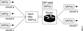 Incoming SAP Packet Filtering
Outgoing SAP packets are filtered when they are generated. This filtering is specific to each IPX-managed circuit. It permits access to a circuit or group of circuits to be restricted selectively.
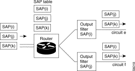 Outgoing SAP Packet Filtering
The coupling of service tables with the RIP routing table also allows service filtering.
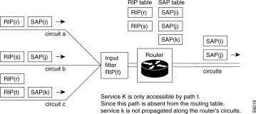 Positioning of Filters
These filters can be positioned during the configuration of the equipment or during operation.
Allowing for filtering parameters
Filtering parameters are allowed for in the initialization of the IPX router.
Ping
The Ping protocol conforming to the Novell specification is implemented over IPX and is always active.
SNMP management
IPX MIB
System Group - Basic System Table
ipxBasicSysInstance integer 32 bits RW Should be equal to 1
ipxBasicSysExistState integer 32 bits
off(1)
on(2) RW The validity of this entry in the IPX system table Setting this field to off indicates that this entry may be deleted from the system table at the IPX implementation's discretion
ipxBasicSysNetNumber NetNumber RW The network number portion of the IPX address of this system.
ipxBasicSysNode string (size=6) RW The node number portion of the IPX address of this system.
ipxBasicSysName string (size=0.48) RW The readable name for this system
ipxBasicSysInReceives counter R The total number of IPX packets received, including those received in error
ipxBasicSysInHdrErrors counter R The number of IPX packets discarded due to errors in their headers, including any IPX packet with a size less than the minimum of 30 bytes
ipxBasicSysInUnknownSockets counter R The number of IPX packets discarded because the destination socket was not open
ipxBasicSysInDiscards counter R The number of IPX packets received but discarded due to reasons other than those accounted for by ipxBasicSysInHdrErrors, ipxBasicSysInUnknownSockets, ipxAdvSysInDiscards, and ipxAdvSysInCompressDiscards
ipxBasicSysInBadChecksums counter R The number of IPX packets received with incorrect checksums
ipxBasicSysInDelivers counter R The total number of IPX packets delivered locally, including packets from local applications
ipxBasicSysNoRoutes counter R The number of times no route to a destination was found.
ipxBasicSysOutRequests counter R The number of IPX packets supplied locally for transmission, not including any packets counted in ipxAdvForwPackets
ipxBasicSysOutMalformedRequests counter R The number of IPX packets supplied locally that contained errors in their structure
ipxBasicSysOutDiscards counter R The number of outgoing IPX packets discarded due to reasons other than those accounted for in ipxBasicSysOutMalformedRequests, ipxAdvSysOutFiltered, and ipxAdvSysOutCompressDiscards
ipxBasicSysOutPackets counter R The total number of IPX packets transmitted
ipxBasicSysConfigSockets integer 32 bits R The configured maximum number of IPX sockets that may be open at one time
ipxBasicSysOpenSocketFails counter R The number of IPX socket open calls which failed
Advanced System Table
ipxAdvSysInstance integer 32 bits RW Must be equal to 1
ipxAdvSysMaxPathSplits integer 32 bits RW The number of paths in parallel that the router is authorized to manage. From 1 to 32.
ipxAdvSysMaxHops integer 32 bits RW The maximum number of hops a packet may take
ipxAdvSysInTooManyHops counter R The number of IPX packets discarded due to exceeding the maximum hop count.
ipxAdvSysInFiltered counter R The number of incoming IPX packets discarded due to filtering
ipxAdvSysInCompressDiscards counter R Not significant
ipxAdvSysNETBIOSPackets counter R The number of NETBIOS packets received
ipxAdvSysForwPackets counter R The number of IPX packets forwarded.
ipxAdvSysOutFiltered counter R The number of outgoing IPX packets discarded due to filtering
ipxAdvSysOutCompressDiscards counter R Not significant
ipxAdvSysCircCount counter R The number of circuits known to this instance of IPX
ipxAdvSysDestCount counter R The number of currently reachable destinations known to this instance of IPX
ipxAdvSysServCount counter R The number of services known to this instance of IPX
Circuit Group - Circuit table
ipxCircSysInstance integer 32 bits RW Must be equal to 1
ipxCircIndex integer 32 bits RW Circuit identifier
ipxCircExistState integer 32 bits
off (1)
on(2) RW The validity of this circuit entry. A circuit with this value set to off may be deleted from the table at the IPX implementation's discretion
ipxCircOperState integer 32 bits
RW The operational state of the circuit:
down(1), - up(2), - sleeping(3)
ipxCircIfIndex integer 32 bits RW The value of ifIndex for the interface used by this circuit. This value may be written only when creating a new entry in the table
ipxCircName
ipxCircDialName string (size = 0...48) RW The name of the circuit
ipxCircType integer 32 bits RW The type of circuit:
other(1), - broadcast(2), - ptToPt(3), - dynamic(6)
ipxCircLocalMaxPacketSize integer 32 bits RW The maximum size (including header), in bytes, that the system supports locally on this circuit
ipxCircCompressState integer 32 bits
off (1) / on(2) RW Not significant
ipxCircCompressSlots integer 32 bits RW Not significant
ipxCircStaticStatut integer 32 bits
unknown(1)
current(2)
changed(3)
read(4)
reading(5)
write(6)
writing(7) RW Not significant
ipxCircCompressedSent counter R Not significant
ipxCircCompressedInitSent counter R Not significant
ipxCircCompressedRejectsSent counter R Not significant
ipxCircUncompressedSent counter R Not significant
ipxCircCompressedReceived counter R Not significant
ipxCircCompressedInitReceived counter R Not significant
ipxCircCompressedRejectsReceived counter R Not significant
ipxCircUncompressedReceived counter R Not significant
ipxCircMediaType string (2) R The media type used on this circuit
ipxCircNetNumber NetNumber RW The IPX network number of this circuit. This value may be written only when creating a new entry in the table
ipxCircStateChanges counter R The number of times the circuit has changed state
ipxCircInitFails counter R The number of times that initialization of this circuit has failed
ipxCircDelay counter R The period of time, in milliseconds, that it takes to transmit one byte of data, excluding protocol headers, to a destination on the other end of the circuit, if the circuit is free of other traffic
ipxCircThroughput integer 32 bits R The amount of data, in bits per second, that may flow through the circuit if there is no other traffic
ipxCircNeighRouterName string (size = 0...48) R The name of the neighboring router on a WAN circuit
ipxCircNeighInternalNetNum NetNumber R The internal network number of the neighboring router
Forwarding group - Destination table
ipxDestSysInstance integer 32 bits R Must be equal to 1
ipxDestNetNum NetNumber R The IPX network number of the destination
ipxDestProtocol integer 32 bits
other(1)
local(2)
rip(3)
nlsp(4)
static(5) R The routing protocol from which knowledge of this destination was obtained
ipxDestTicks integer 32 bits R The delay in ticks to reach this destination
ipxDestHopCount integer 32 bits R The number of hops necessary to reach the destination
ipxDestNextHopCircIndex integer 32 bits R The unique identifier of the circuit used to reach the next hop
ipxDestNextHopNICAddress PhysAddress R The NIC address of the next hop
ipxDestNextHopNetNum NetNumber R The IPX network number of the next hop
Forwarding group - Statistic Routes table
ipxStaticRouteSysInstance integer 32 bits RW Must be equal to 1
ipxStaticRouteCircIndex integer 32 bits RW The identifier of the circuit to reach the first next hop
ipxStaticRouteNetNum NetNumber RW The IPX network number of the route's destination
ipxStaticRouteExistState integer 32 bits
off(1)
on(2) RW The validity of this static route. Entries with the value set to off may be deleted from the table at the implementation's discretion.
ipxStaticRouteTicks integer 32 bits RW The delay, in ticks, to reach the route's destination
ipxStaticRouteHopCount integer 32 bits RW The number of hops necessary to reach the destination
Services Group - Services Table
ipxServSysInstance integer 32 bits R Must be equal to 1
ipxServType string (size=2) R The service type
ipxServName string (size=1-48) R The service name
ipxServProtocol integer 32 bits
other(1),
local(2),
nlsp(4),
static(5),
sap(6) R The protocol from which knowledge of this service was obtained.
ipxServNetNum NetNumber R The IPX network number portion of the IPX address of the service.
ipxServNode string (size=6) R The node portion of the IPX address of the service
ipxServSocket string (size=2) R The socket portion of the IPX address of the service
ipxServHopCount integer 32 bits R The number of hops to the service
Services Group - Destination Services Table
ipxDestServSysInstance integer 32 bits R Must be equal to 1
ipxDestServNetNum NetNumber R The IPX network number portion of the IPX address of the service
ipxDestServNode string (size=6) R The node portion of the IPX address of the service
ipxDestServSocket string (size=2) R The socket portion of the IPX address of the service
ipxDestServName string (size=1.48) R The name of the service
ipxDestServType string (size=2) R The type of service
ipxDestServProtocol integer 32 bits R The protocol from which knowledge of this service was obtained.
- other(1), - local(2), - nlsp(4), - static(5), - sap(6)
ipxDestServHopCount integer 32 bits R The number of hops to the service
Services Group - Statistics Services Table
ipxStaticServSysInstance integer 32 bits RW Must be equal to 1
ipxStaticServCircIndex integer 32 bits RW The circuit used to reach this service
ipxStaticServName string (size=1.48) RW The name of the service
ipxStaticServType string (size=2) RW The type of service
ipxStaticServExistState integer 32 bits
off(1)
on(2) RW The validity of this static service. Entries with the value set to off may be deleted from the table at the implementation's discretion.
ipxStaticServNetNum NetNumber RW The IPX network number portion of the IPX address of the service
ipxStaticServNode string (size=6) RW The node portion of the IPX address of the service
ipxStaticServSocket string (size=2) RW The socket portion of the IPX address of the service
ipxStaticServHopCount integer 32 bits RW The number of hops to the service
MIB RIP/SAP
System Group - RIP System Table
ipxBasicSysInstance integer 32 bits RW Must be equal to 1
ripSysInstance integer 32 bits RW Must be equal to 1
ripSysState integer 32 bits
off(1)
on(2) RW Indicates the operational state of this instance of RIP
ripSysIncorrectPackets counter R The number of times that an incorrectly formatted RIP packet was received
System Group - SAP System Table
sapSysInstance integer 32 bits RW Must be equal to 1
sapSysState integer 32 bits
off(1)
on(2) RW Indicates the operational state of this instance of SAP
sapSysIncorrectPackets counter RW The number of times that an incorrectly formatted SAP packet was received
Circuit Group - RIP Circuit Table
ripCircSysInstance integer 32 bits RW Must be equal to 1
ripCircIndex integer 32 bits RW Circuit identifier
RipCircState integer 32 bits
off(1)
on(2)
auto-on(3)
auto-off(4) RW Indicates whether RIP information may be sent/received over this circuit:
ripCircPace integer 32 bits RW The maximum pace, in packets per second, at which RIP packets may be sent on this circuit
ripCircUpdate integer 32 bits RW The RIP periodic update interval, in seconds (default = 60)
ripCircAgeMultiplier integer 32 bits RW The holding multiplier for information received in RIP periodic updates
ripCircPacketSize integer 32 bits RW The RIP packet size used on this circuit
ripCircOutPackets counter R The number of RIP packets sent on this circuit
ripCircInPackets counter R The number of RIP packets received on this circuit
Circuit Group - SAP Circuit Table
sapCircSysInstance integer 32 bits RW Must be equal to 1
sapCircIndex integer 32 bits RW Circuit identifier
sapCircState integer 32 bits
off(1)
on(2)
auto-on(3)
auto-off(4) RW Indicates whether SAP information may be sent/received over this circuit.:
sapCircPace integer 32 bits RW The maximum pace, in packets per second, at which SAP packets may be sent on this circuit
sapCircUpdate integer 32 bits RW The SAP periodic update interval, in seconds (default = 60)
sapCircAgeMultiplier integer 32 bits RW The holding multiplier for information received in SAP periodic updates (default = 4)
sapCircPacketSize integer 32 bits RW The SAP packet size used on this circuit
sapCircGetNearestServerReply integer 32 bits
no(1)
yes(2) RW Indicates whether to respond to SAP get nearest server requests received on this circuit
sapCircOutPackets counter R The number of SAP packets sent on this circuit
sapCircInPackets counter R The number of SAP packets received on this circuit
Example of IPX configuration
The network of the figure oposite present an interconnection between two Ethernet networks via a PPP line. On each of the Ethernet networks, there is a NetWare server with a few clients. The NetWare servers are named Canesh and Shiva. The encapsulation used on the Ethernet networks is encapsulation type IEEE 802.2. The PPP synchronous line connects the two routers respectively to their line 0.
The IPX addresses are:
The internal networks of the Canesh and Shiva servers are respectively CCCC0001 and AAAA0001.
To activate the IPX protocol on the routers, parameter 1 is put into C53R0P0. The names of the routers are placed in C53R1P0.
On each of the routers in class 54, two IPX circuits are declared. Circuit 1 is connected to virtual port 3 which is mapped on line 3 (mapping is accomplished via the parameters of C35R1P0). Circuit 1 is thus of the broadcast type. On the other hand, circuit 2 is a point to point circuit because it is connected to virtual port 2 which is mapped on line 0 configured with profile 123, i.e. the synchronous PPP profile.
The circuits receive an IPX address at C54R2P0 and a name at C54R3P0. The type of encapsulation on circuit 1 is given in C54R4P0, in the example the encapsulation is IEEE 802.2. Circuit 2 leading to the remote router receives an X121 address at C54R6P0, and a MAC type artificial address at C54R7P0. The MAC artificial address is used to designate the equipment on circuit 2, whereas the X121 address is used for calling the remote router. The subscriber number used in the X121 address of this example is 43. This subscriber number is configured at C33R0P0, and designates the entry point to line PPP.
On none of the circuits can IPX level filtering be used (C55R2P0=0). The parameters from C55R6 to C55R8 are not configured.
The broadcasting of frames Type20 on all the circuits is authorized. Parameter C55R0P0 equal to 2, allows broadcasting on all the circuits.
NCP spoofing is not validated on the inter-router circuit (C55R2P3=0).
The RIP and SAP protocols are activated on each of the routers (C56R0P0=1 pour RIP and C57R0P0=1 for SAP). No RIP filtering is declared:
The same applies to SAP with C57ROP1=0 and C57R15 to R18 not configured.
The RIP operating parameters are:
The same operating parameters are used for the SAP protocol (C57R2 and C57R3).
The response function to "Get Nearest Server" of the routers is activated on the broadcast circuits of each of the routers (C54R4P0=1). This function enables the customers of a network to connect to the remote NetWare server in case of maintenance being carried out on the local NetWare server.
A static service is declared on each of the routers (C57R5 to C55R10). These static services are declared on routes that are also declared in the static mode (C55R3 to C55R5).
Config PPP - Router 1 Config PPP - Router 2
C01 R1 P0=39 P3=23 C01 R1 P0=39 P3=23
C01 R2 P0=900010 C01 R2 P0=900020
C09 R2 P0=20 C09 R2 P0=10
C09 R3 P0=1,1,0,1 C09 R3 P0=1,1,0,1
C09 R4 P0=40 P43=43 C09 R4 P0=40 P43=43
C09 R5 P0=1,1,0,0 P43=1,1,0,43 C09 R5 P0=1,1,0,0 P43=1,1,0,43
C12 R0 P0=123 P1=46,40 P2=103,1 C12 R0 P0=123 P1=46,40 P2=103,1
C12 R0 P3=104,1 P4=105,1 P5=106,0 C12 R0 P3=104,1 P4=105,1 P5=106,0
C12 R3 P0=90 P1=1,3 P2=2,0 P3=3,0 P4=4,0 C12 R3 P0=90 P1=1,3 P2=2,0 P3=3,0 P4=4,0
C33 R0 P0=0,43,2 C33 R0 P0=0,43,2
Virtual ports and connections Virtual ports and connections
C35 R0 P0=1,3,0,0 P1=1,2,1,0 C35 R0 P0=1,3,0,0 P1=1,2,1,0
C35 R1 P0=1,3,3 C35 R1 P0=1,3,3
C36 R0 P0=90001040 C36 R0 P0=90002040
C36 R2 P0=2,0,0 C36 R2 P0=2,0,0
IPX Parameterizing IPX Parameterizing
C53 R0 P0=1 P1=1 P2=16 C53 R0 P0=1 P1=1 P2=16
C53 R1 P0=ROUTEURGANESH C53 R1 P0=ROUTEURSHIVA
IPX circuits parameterizing IPX circuits parameterizing
C54 R0 P0=1,1,3,0 P1=1,2,2,0 C54 R0 P0=1,1,3,0 P1=1,2,2,0
C54 R1 P0=1,2,1500 P1=1,3,1500 C54 R1 P0=1,2,1500 P1=1,3,1500
C54 R2 P0=CCCC0003 P1=BBBB0001 C54 R2 P0=AAAA0003 P1=BBBB0001
C54 R3 P0=circuita P1=circuitb C54 R3 P0=circuita P1=circuitb
C54 R4 P0=1,1,2 C54 R4 P0=1,1,2
C54 R5 P0=1,2 C54 R5 P0=1,2
C54 R6 P0=90002043 C54 R6 P0=90001043
C54 R7 P0=BBBBBB020202 C54 R7 P0=BBBBBB010101
IPX routing parameterizing IPX routing parameterizing
C55 R0 P0=2 C55 R0 P0=2
C55 R1 P0=1,1 P1=1,2 C55 R1 P0=1,1 P1=1,2
C55 R2 P0=0,1,0 P1=0,1,0 C55 R2 P0=0,1,0 P1=0,1,0
C55 R3 P0=EEEE0001 C55 R3 P0=DDDD0001
C55 R4 P0=1,2,1 C55 R4 P0=1,2,1
C55 R5 P1=300 C55 R5 P1=300
RIP parameterizing RIP parameterizing
C56 R0 P0=1 P1=0 C56 R0 P0=1 P1=0
C56 R1 P0=1,1,1,0 P1=1,2,1,0 C56 R1 P0=1,1,1,0 P1=1,2,1,0
C56 R2 P0=4,100,60 P1=4,100,60 C56 R2 P0=4,100,60 P1=4,100,60
C56 R3 P0=512 P1=512 C56 R3 P0=512 P1=512
SAP parameterizing SAP parameterizing
C57 R0 P0=1 P1=0 C57 R0 P0=1 P1=0
C57 R1 P0=1,1,1,0 P1=1,2,1,0 C57 R1 P0=1,1,1,0 P1=1,2,1,0
C57 R2 P0=4,100,60 P1=4,100,60 C57 R2 P0=4,100,60 P1=4,100,60
C57 R3 P0=512 P1=512 C57 R3 P0=512 P1=512
C57 R4 P0=1 P1=0 C57 R4 P0=1 P1=0
C57 R5 P0=SERVICESTATIQUEEEEE0001 C57 R5 P0=SERVICESTATIQUEDDDD0001
C57 R6 P0=3615 C57 R6 P0=3615
C57 R7 P0=1,2,2 C57 R7 P0=1,2,2
C57 R8 P0=EEEE0001 C57 R8 P0=DDDD0001
C57 R9 P0=EEEEEE000001 C57 R9 P0=DDDDDDDD000001
C57 R10 P0=1521 C57 R10 P0=1521
CLNP routing function
General
The CLNP Router function allows the interconnection of local networks of the Ethernet type through a Frame Relay, X.25 or PPP remote network in accordance with applicable standards:
Source Reference Title and Contents
ISO 8348/Ad2 Information processing systems - Data communications -
Network service definition.
Addendum 2: Network layer addressing.
ISO 8473 Information processing systems - Data communications -
Protocol for providing the connection less-mode network service.
ISO 9542 Information processing systems -
Telecommunications and information exchange between systems -
End system to Intermediate system routing exchange protocol for use in conjunction with [ISO 8473].
Type of remote network
Source Reference Title and contents
X.25 IAB RFC1356 Multiprotocol Interconnect on X.25 and ISDN in the Packet Mode
Frame Relay IAB RFC1490 Multiprotocol Interconnect over Frame Relay
PPP IAB RFC1548 The Point-to-Point Protocol (PPP)
Addressing
NET addresses and NSAP addresses:
In an OSI architecture,
The NSAP address allowing access to a higher layer protocol differs from the NET address of the underlying network entity by its last byte. This byte identifies the protocol accessible through the network entity. The same equipment may have several NET addresses; one per host network entity. The same equipment may have several NSAP addresses; one per resident protocol accessible via the host network entity/entities.
In the case of LANPAC equipment operating as a CLNP Router:
Structured addressing:
The CLNP Router function is sometimes required, in connection with PDU routing, to handle NET addresses and NSAP addresses.
The CLNP Router function supports all the NSAP address formats defined in ISO standard 8348/Ad 2. Further, it takes into account the address structuring defined in ISO 10589.
During configuration, all NET and NSAP addresses handled by the equipment are considered in a structured manner relative to ISO 8348/Ad2 and ISO 10589. A test is performed to ensure that all these addresses comply with such standards.
NET or NSAP addresses of IS neighbors, ES neighbors or remote equipment.
Domain Area System Sel
Non-structured address:
During the routing of a PDU, the CLNP Router function considers the NET or NSAP destination address of the PDU globally: as a series of bytes without any particular structure.
This behavior allows the provision of a routing service by prefix.
Series of bytes making up the address
The Reference Publication Format (RPF)
The RPF address format is defined in ISO 8348 / DAM4.
This address format, based on a string of ASCII characters, is used in man/machine interfaces. It is applied when addresses are entered during configuration.
< IDP > [ + < DSP > ] < null >
An RPF address consists of a string of ASCII characters with a maximum length of 42 characters (including the < null > character delimiting the end of the string). The address is broken down into four parts:
Preferred Binary Encoding (PBE) format address
The PBE format is defined by ISO 8348 / Add 2.
This address format is used to code NSAP and NET fields of PDU headers relative to the ISO ISO 8473, ISO 9542 and ISO 10589 protocols.
< AFI > [ [ < leading pad > ] < IDI > [ < trailing pad > ] ] [ < DSP > [ < trailing pad > ] ]
The PBE format address is made up of a string of bytes with a maximum length of 20 bytes. The address is broken down into five parts:
CRP format address
The CRP input format is the same as the RPF except for two points: the separator between the IDP and the DSP is not a plus '+' but 'A', and the first byte entered contains, in hexadecimal, the total size (including separator 'A') of the address.
Service rendered
Dynamic routing: implementation of ES-IS protocol on LAN side
The only dynamic routing service rendered by the CLNP Router function is the implementation of the ES-IS protocol on the local interface(s) of the equipment.
The implementation of the ES-IS protocol is not configurable: this protocol is enabled automatically on all the local interfaces. The CLNP Router function does not implement the ES-IS protocol on a remote interface.
The ES-IS protocol makes it possible to determine all the ES equipment present on the directly accessible Ethernet network(s). This results in the learning of the @NETorNSAP <-> @MAC correspondence of the ES and by the keeping of this correspondence in a cache memory.
The equipment shows only the ESs implementing the ES-IS protocol. For the others, it is possible to use a static cache.
Static routing: static routing information during configuration
The CLNP Router function provides a static router service, which may be explicit or by prefix, between the interfaces of the equipment. Explicit routing allows a particular equipment to be reached with a complete NET or NSAP address. Prefix routing allows an equipment group to be reached with the address prefix shared by all the equipment in the group.
The combination of these two basic services allows the rendering of three static routing services when the addressing plan of the architecture complies with ISO 10589:
All the information enabling these routing services to be rendered are furnished statically during the configuration of the equipment.
Routing criteria:
The routing of a PDU consists in receiving it on one of the interfaces of the equipment and sending it through the interface allowing the destination party to be reached. Accessibility may be direct (the destination is a neighbor of the equipment) or indirect (the destination is accessible through another router which is itself a neighbor of the equipment).
The CLNP Router function extracts the NET or NSAP destination address of the PDU to be routed and then examines its routing table. The routing table contains, for each input, a correspondence of the type @NETorNSAPorPREFIXE <-> output interface, SNAP address of the neighbor. The chosen input will be the one whose @NETor@NSAPorPREFIXE field corresponds closest to the destination address of the PDU to be routed.
Routing information
Dynamic routing information:
The only dynamic routing information handled by the CLNP Router function is what is learnt by the ES-IS protocol. Such information is placed in a cache memory and contains the @NETorNSAP <-> @MAC correspondence of the ES equipment present in the Ethernet network(s) and using the ES-IS protocol.
Static routing information:
The CLNP Router function handles two types of static routing information, namely neighbor accessibility and remote accessibility information.
Neighbor accessibility information concerns all IS neighbors, all ES neighbors accessible on the WAN side, as well as ES neighbors on the LAN side not implementing the ES-IS protocol. Neighbor accessibility information is made up of the @NETorNSAP <-> @SNPA correspondence. On the WAN side, an SNPA address is an address of the X.121 type whereas on the LAN side it is a MAC type address.
Remote accessibility information concerns either a special protocol on special equipment addressed by means of an @NSAP, or special equipment addressed by means of an @NET, or even a group of equipment addressed by a PREFIX. Remote accessibility information is made up of the correspondence @NETorNSAPorPREFIXE <-> neighbor in which neighbor identifies the IS equipment declared as being a neighbor and enabling the destination party to be reached.
Remote neighboring and accessibility information supplied during configuration is placed in the routing table when the CLNP Router function is initialized.
Configuration examples
Configuration of CLNP routing function
The configurations presented in the following paragraphs concern:
Activation of CLNP routing function
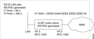 Activation of CLNP Routing Function
Activation of CLNP Router function
C52-R0-P0 = 1 activation yes
Activation of ER-PDU transmission
C52-R0-P1 = 1 activation yes
Assignment of global NET address
C52-R1-P0 = 1D 47 00 04 A DD DD AA AA EE EE EE EE EE EE 00
Table of virtual ports
C52-R2-P0 = 1, 2 ,1,0 valid state, virtual port 2, activation yes, reserved
C52-R2-P1 = 1, 3 ,1,0 valid state, virtual port 3, activation yes, reserved
C52-R3-P0 = 1500 MTU of 1500 bytes on virtual port 2
C52-R3-P1 = 1500 MTU of 1500 bytes on virtual port 3
Table of local virtual ports
C52-R4-P0 = 1, 3 ,0,0 valid state, virtual port 3, ER-PDU processing no, reserved
C52-R5-P0 = 60 configuration ES-IS timer of 30 seconds on virtual port 3
C52-R6-P0 = 300 maintenance ES-IS timer of 300 seconds on virtual port 3
Intra-domain static routing by prefix
 Intra-domain Static Routing by Prefix
Purpose: Obtain end-to-end static routing between two LANs located in two areas of the same domain.
Configuration: A static route allowing access to area 0002 (respectively 0001) of the domain 47 0004 + 0001 is placed in the routing table of Router-1 (respectively Router-2).
Configuration of Router-1:
Table of neighbors
C52-R7-P0 = 1, 0 ,1,2 valid state, neighbor 0, IS type, through virtual port 2
C52-R8-P0 = 1D 47 00 04 A 00 01 00 02 00 00 00 00 00 02 00
Table of remote neighbors
C52-R11-P0 = 1, 0 valid state, neighbor 0
C52-R12-P0 = 90 00 20 43 SNPA address of the X.121 type
Routing table
C52-R13-P0 = 1, 0 valid state, via neighbor 0
C52-R8-P0 = 0F 47 00 04 A 00 01 00 02
Configuration of Router-2:
Table of neighbors
C52-R7-P0 = 1, 0 ,1,2 valid state, neighbor 0, IS type, through virtual port 2
C52-R8-P0 = 1D 47 00 04 A 00 01 00 01 00 00 00 00 00 01 00
Table of remote neighbors
C52-R11-P0 = 1, 0 valid state, neighbor 0
C52-R12-P0 = 90 00 10 43 SNPA address of the X.121 type
Routing table
C52-R13-P0 = 1, 0 valid state, via neighbor 0
C52-R8-P0 = 0F 47 00 04 A 00 01 00 01
Inter-domain static routing by prefix
Objective: Provide end-to-end static routing between two LANs located in two different domains.
Configuration: A static route giving access to domain 47 0004 + 0002 (respectively 47 0004 + 0001) is placed in the routing table of Router-1 (receptively Router-2).
Configuration of Router-1:
Table of neighbors
C52-R7-P0 = 1, 0 ,1,2 valid state, neighbor 0, IS, through virtual port 2
C52-R8-P0 = 1D 47 00 04 A 00 02 00 04 00 00 00 00 00 06 00
Table of remote neighbors
C52-R11-P0 = 1, 0 valid state, neighbor 0
C52-R12-P0 = 90 00 20 43 SNPA address of the X.121 type
Routing table
C52-R13-P0 = 1, 0 valid state, via neighbor 0
C52-R8-P0 = 0B 47 00 04 A 00 02
Configuration of Router-2:
Table of neighbors
C52-R7-P0 = 1, 0 ,1,2 valid state, neighbor 0, IS type, through virtual port 2
C52-R8-P0 = 1D 47 00 04 A 00 01 00 03 00 00 00 00 00 05 00
Table of remote neighbors
C52-R11-P0 = 1, 0 valid state, neighbor 0
C52-R12-P0 = 90 00 10 43 SNPA address of the X.121 type
Routing table
C52-R13-P0 = 1, 0 valid state, via neighbor 0
C52-R8-P0 = 0B 47 00 04 A 00 01
![]()
![]()
![]()
![]()
![]()
![]()
![]()
![]()
Posted: Thu Jan 25 14:17:02 PST 2001
All contents are Copyright © 1992--2001 Cisco Systems, Inc. All rights reserved.
Important Notices and Privacy Statement.