MGX switches display alarm information about the switch cards and store this information inside the switch. This chapter describes how to interpret the alarm LEDs on the switch and how to obtain alarm reports through the CLI.
Viewing and Responding to Alarms Using Physical Switch Controls
The PXM1E cards, SRM cards, and service modules have LEDs for viewing alarm status and switches for responding to alarms. The following sections describe the controls on the PXM1E service module. To see the LEDs on the SRM cards and the service modules, refer to the Cisco MGX 8850 Hardware Installation Guide (PXM45/B and PXM1E)
PXM1E Card Controls
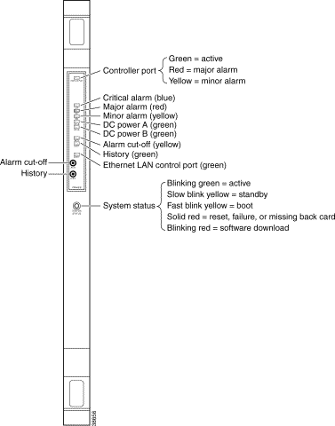
Figure 11-1 shows the LEDs and switches available on the front of the PXM1E card. Table 11-1 describes these controls.
Note Although there are LEDs for critical, major, and minor alarms on the PXM45, only one of these LEDs
is set to "on" when multiple alarms are active. The switch always displays the status of the most severe
alarm. Critical alarms are the most severe, and minor alarms are the least severe. If there were 2 major
alarms and 10 minor alarms, the switch would set the major alarm LED to on.
Figure 11-1 PXM1E Front Card Controls
Table 11-1 LED Indicators for PXM1E
LED Label
Color
Meaning
CNTRLR Port (Controller Port)
Green
Controller port is active.
Red
Major alarm on the controller port.
Yellow
Minor alarm on the controller port.
None
No light indicates the port has not been activated (upped).
CR (Critical alarm)
Blue
A critical alarm indicates a condition that results in a loss of service for which the switch cannot correct. For example, when APS redundancy is not present, a broken trunk cable generates a critical alarm. Immediate action is required.
MJ (Major alarm)
Red
A major alarm indicates a component or service failure that currently has minimal impact on service. For example, if one card in a redundant PXM1E configuration fails, the good card takes over and the switch displays a major alarm. Urgent action is required to recover the failed component or service.
MN (Minor alarm)
Yellow
A minor alarm indicates a non-service affecting condition that should be corrected. Minor alarms can indicate internal switch failures, such as the failure of a single fan, or external failures that cannot be corrected at the switch.
DC-A
Green
Green indicates that the power supplies in tray A are functioning.
None
No light indicates that power supply tray A is empty (no power modules).
DC-B
Green
Green indicates that the power supplies in tray B are functioning.
None
No light indicates that power supply tray B is empty (no power modules).
ACO (Alarm cut-off)
Yellow
Yellow indicates that the ACO switch was pushed to clear the audible alarm indicator, but the alarm condition still exists.
HIST (History)
Green
Green indicates that a network alarm occurred. Critical and major alarms clear automatically when the problem is resolved. Minor alarms remain lit until cleared with the history button. If there are critical or major alarms in progress, you cannot reset the HIST light. If the card indicates a minor alarm, press the HIST button once to see if the alarm condition has passed. When all alarms are cleared, press the HIST button to turn off the HIST LED.
ENET (Ethernet)
Green
Blinking green indicates that there is activity on the LAN Control Port.
System Status
Green
Blinking green indicates that the card is in the active state.
Yellow
Slow blinking yellow indicates that the card is in the standby state.
Fast blinking yellow indicates that the card is in the boot state.
Red
Solid red indicates that the card is in the Reset state, the card has failed, or a back card is missing.
Blinking red indicates that the card is downloading new software.
RPM-PR Card Controls
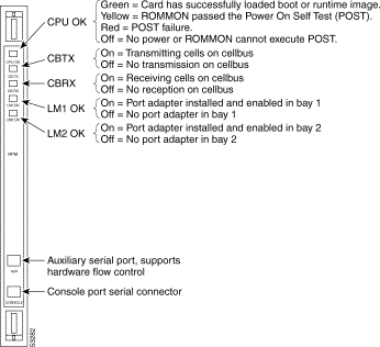
Figure 11-2 shows the LEDs available on the front of the RPM-PR card. Table 11-2 describes these LEDs.
Figure 11-2 RPM-PR Card Controls
Table 11-2 LED Indicators for RPM-PR Card
LED
Color
Description
CPU OK
Green
RPM-PR has successfully loaded the boot or runtime software.
Yellow
ROMMON passed the POST1.
Red
POST failure.
Off
No power or ROMMON cannot execute POST.
CB TX
On
Transmitting cells on cellbus.
Off
Not transmitting cells on cellbus.
CB RX
On
Receiving cells from cellbus. This light stays on solid when downloading software.
Off
Not receiving cells from cellbus.
LM1 OK
On
Port adapter installed and enabled in bay 1.
Off
No port adapter installed in bay 1.
LM2 OK
On
Port adapter installed and enabled in bay 2.
Off
No port adapter installed in bay 2.
1 POST = Power On Self Test
Displaying Alarm Reports in the CLI
You can use a CLI session to view the status of node alarms. Alarms are reported in the following categories:
Node alarms
Clock alarms
Switching alarms
Environment alarms
Card alarms
The sections that follow describe how to display the different types of alarm reports.
Note The procedures in the following sections can be completed by users at all access levels.
Displaying Node Alarms
A node alarm report displays a summary report of all alarms on the node. To display node alarms, enter the following command:
mgx8830a.2.PXM.a> dspndalms
The following example shows the node alarm report display.
mgx8850a.2.PXM.a> dspndalms
Node Alarm Summary
Alarm Type Critical Major Minor
---------- -------- ------- -------
Clock Alarms 0 0 2
Switching Alarms 0 0 0
Environment Alarms 0 0 0
Card Alarms 0 0 0
Typically, you would start investigating alarms by displaying the node alarms. Once you have identified the area that is producing the alarms, you would enter additional commands to display detailed information on those alarms. The following sections describe how to display these detailed reports.
Displaying Clock Alarms
MGX switches monitor the quality of the clock sources. If the timing for a clock source strays beyond the tolerance thresholds, an alarm is reported. To view the clock alarms, enter the following command:
mgx8850a.2.PXM.a> dspclkalms
The following is an example clock alarm report:
mgx8850a.2.PXM.a> dspclkalms
mgx8850a System Rev: 03.00 May. 06, 2002 22:47:36 GMT
MGX8830 Node Alarm: MINOR
Clock Manager Alarm Summary
----------------------------
NETWORK CLOCK ALARM : STANDBY LOST PRIMARY REFERENCE : MINOR
NETWORK CLOCK ALARM : STANDBY LOST SECONDARY REFERENCE : MINOR
Critical Major Minor
000 000 002
Displaying Switching Alarms
Switching alarms identify problems with the switching components within the switch. To display a report of all switching alarms, enter the following command:
mgx8850a.2.PXM.a> dspswalms
The following is a sample report showing no switching alarms.
mgx8850a.2.PXM.a> dspswalms
XBAR SWITCHING FABRIC ALARMS SUMMARY
Xbar Core Alarm Xbar Port Alarm Xbar Slot B/W alarm
Slot No. Critical Major Minor Critical Major Minor Critical Major Minor
Displays the following general information about the configuration of a switch plane (switching fabric or crossbar):
Number of the slot where the crossbar ASIC resides (7 or 8 for a Cisco MGX 8850 switch, and slots 1 and 2 of a Cisco MGX 8850 node).
Selected switch plane or ASIC number. The range is 0 to 3. If you do not specify a plane with this command, the default value of 0 is used.
Revision number of the ASIC.
Status of the ASIC. The status is either failed or OK. If the status is failed, the other ASICs must carry the switching load, and the throughput of the switch falls below the maximum. In this case, Cisco Systems recommends you replace the card. The cell grant mode is always "Multicast Preferred."
The "Resent Sframe Tic" is the rising edge of the clock. "Sframe" refers to a switch frame.
dspxbaralm
Shows whether a crossbar alarm is minor, major, or critical. The display shows status on both the active and standby PXM1E.
dspxbarerrcnt
Displays the following types of slot-link errors:
Loss of synchronization between the ASIC and the queuing circuitry on the service module. The synchronization in this case applies to the timing of the internal switching frames (Sframes). Loss of synchronization is a very serious error.
Receiver code violations (Rx Cv column in the display).
Receiver disparity errors (Rx Disp column in the display). A disparity error is a summary of five ASIC-specific alarms.
Transmitter parity errors.
CRC failures for the header or the payload of the 60-byte Sframe.
Failures to remap between slots as needed or excessive remapping between slots (Slot Remap and Slot Recur columns in the display).
Parity errors in back-pressure messages.
dspxbarerrthresh
Displays the thresholds for crossbar errors. The items that make up a threshold are as follows:
Duration of the errored state
Number of errors during that time period
Upper and lower error counts within a particular alarm severity (minor, major, and critical)
Thresholds are displayed for the following errors:
Loss of synchronization (LossOfSync)
Transceiver error (TranscieverErr)
DisparityErr—Accumulation of five ASIC-level errors
ParityErr—Parity error in the switch frame as a whole
HeaderCRCErr—CRC error for the switch frame header
PayloadCRCErr—CRC error for the switch frame payload
RemapTwiceErr
RemapRecurrErr
Backpressure parity error (B.P.ParityErr)—Parity error in the signaling for backpressure
dspxbarmgmt
Displays details about the load sharing configuration for the node.
dspxbarstatus
Displays status of each slot for a crossbar.
For more information on these commands, refer to the Cisco MGX 8850, MGX 8950, and MGX 8830 Command Reference (PXM45/B).
Displaying Environment Alarms
An environmental alarm report displays the alarm status and operating statistics for the switch power supplies and cooling fans. To display the environmental alarm report, enter the dspenvalms command as shown in the following example:
mgx8830a.2.PXM.a > dspenvalms
Type <CR> to continue, Q<CR> to stop:
mgx8830a System Rev: 03.00 May 06, 2002 23:40:57 GMT
MGX8830 Node Alarm: MINOR
ENVIRONMENTAL ALARM STATE INFO ^Notification Disabled
+5V Input 4.850^ to 5.150^ VoltsDC 4.997 Informational
+3.3V Input 3.200^ to 3.400^ VoltsDC 3.259 Informational
Calibration VDC 0x7e^ to 0x82^ Other 0x80 Informationall
Displaying Card Alarms
A card alarm report can display the alarm status of all the cards within the node or the alarm status of a single card. To display card alarms, enter the following command:
mgx8830a.2.PXM.a> dspcdalms [slot]
Replace [slot]with the number of the card for which you want to display alarms. If you omit the slot number, the switch displays the alarms for all cards in the node as shown in the following example:
mgx8830a.2.PXM.a> dspcdalms
Card Alarm Summary
Slot Critical Major Minor || Slot Critical Major Minor
To display a list of archived log files, enter the following command:
mgx8830a.2.PXM.a> dsplogs
The log files are stored in the C:/LOG directory.
Displaying IMA Alarms
Enter the dspimagrpalms command to display alarm state information for all IMA groups on the current PXM1E, as shown in the following example:
Unknown.7.PXM.a > dspimagrpalms
Group Number : 2.1
Alarm State : StartUp Fe
Group Number : 2.2
Alarm State : Other Failure
Enter the dspimagrpalm <bay.grpNum> command to display alarm state information for a specific IMA group. Replace bay with the 2 to specify the lower bay. Replace grpNum with the IMA group whose alarm status you want to view.
Note On the PXM1E, the bay number is always 2.
In the following example, the user displays alarm information for the IMA group 11 in the lower bay.
Unknown.7.PXM.a > dspimagrpalm 2.2
Group Number : 2.2
Alarm State : Other Failure
Enter the dspimalnkalms command to display alarm state information for all IMA links on the current PXM1E, as shown in the following example.
Unknown.7.PXM.a > dspimalnkalms
Link Number : 2.5
Alarm State : Lif Fail
Enter the dspimalnk alm <bay.grpNum> command to display alarm state information for a specific IMA group. Replace bay with the 2 to specify the lower bay. Replace grpNum with the IMA group whose alarm status you want to view.
Note On the PXM1E, the bay number is always 2.
In the following example, the user displays alarm information for the IMA group 2 in the lower bay.