|
|

Table Of Contents
Using the VPN 3002 Hardware Client Manager for Quick Configuration
Logging into the VPN 3002 Hardware Client Manager
Uploading an Existing Configuration File
Configuring the Private Interface
Configuration | Quick | Private Interface | Address
Configuration | Quick | Private Interface | DHCP Server
Configuring the Public Interface
Configuring PAT or Network Extension Mode
Online Technical Snapshot Explains PAT and Network Extension Modes
Client Mode with Split Tunneling
VPN Concentrator Settings Required for PAT
Network Extension Mode with Split Tunneling
VPN Concentrator Settings Required for Network Extension Mode
Using Other VPN 3002 Hardware Client Manager Functions
Understanding the VPN 3002 Hardware Client Manager Window
Using the VPN 3002 Hardware Client Manager for Quick Configuration
This chapter tells you how to complete quick configuration of the system using the VPN 3002 Hardware Client Manager.
The VPN 3002 Hardware Client Manager is an HTML-based configuration, administration, and monitoring system built into the VPN 3002. To use it, you need only connect to the VPN 3002 using a PC and browser on the same private network as the VPN 3002.
As you proceed, refer to the data you recorded in Table 2-2.
The figures that follow show only the main frame of the Manager window. To use features in the other frames, see the "Understanding the VPN 3002 Hardware Client Manager Window" section.
Logging into the VPN 3002 Hardware Client Manager
Access and log into the VPN 3002 Hardware Client Manager using these steps:
Step 1
Start the browser. See the "Browser Requirements" section. We recommend using Microsoft Internet Explorer for best results. Maximize the browser window for easiest reading.
Step 2
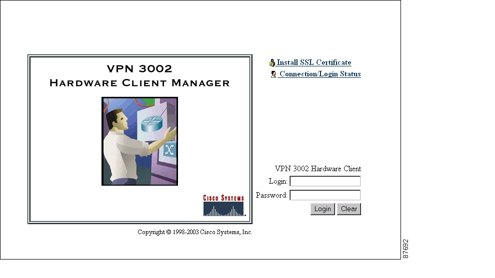
The Manager displays the VPN 3002 Hardware Client Manager Loginscreen.
Figure 3-1 VPN 3002 Hardware Client Login Screen
Step 3
•
•
•
Starting Quick Configuration
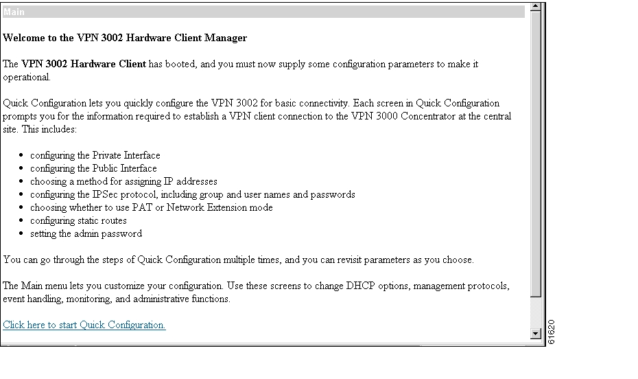
The Manager displays the VPN 3002 Hardware Client Manager Main screen.
Figure 3-2 VPN 3002 Hardware Client Manager Main Screen
To start quick configuration, click the underlined link that says Click here to start Quick Configuration. The Manager displays the Time and Date screen, which is the first of the quick configuration screens.
About Quick Configuration
Text entries are case-sensitive; that is,
adminandADMINare different passwords.After you make an entry in a field, do not press the keyboard Enter key. Just move the cursor from field to field. With Microsoft Internet Explorer, you can press the Tab key to move from field to field; other browsers may work differently.
On any screen where it appears, click the Back button to return to the previous screen.
Configuration entries take effect as soon as you click the Apply or Continue button, and they constitute the active or running configuration.
The banner across the top of the screen indicates the parameter currently displayed, both by showing in the top line the complete path to that parameter, for example, Configuration | Quick | Time and Date, and also by highlighting an abbreviated name of the parameter in the line below, such as Time. For configured parameters, the Manager adds a checkmark to the side of its abbreviated name.
You can go through the steps of quick configuration as many times as you want, and you do not have to proceed sequentially. You can also revisit individual parameters. To reach a screen, click either
–
–
If you make a mistake and see an Error screen with the message, "An error has occurred while attempting to perform the operation," and you return to the screen where you were working, carefully check all your previous entries on that screen. The Manager attempts to retain valid entries, but invalid entries are lost. See Appendix A, "Troubleshooting and System Errors" for more details.
Do not use the browser navigation toolbar buttons Back, Forward, or Refresh / Reload with the VPN 3002 Hardware Client Manager unless instructed to do so. To protect access security, clicking Refresh / Reload automatically logs out the Manager session. Clicking Back or Forward may display stale Manager screens with incorrect data or settings. We recommend that you hide the browser navigation toolbar to prevent mistakes while using the VPN Hardware Client Manager.
Setting the Time and Date
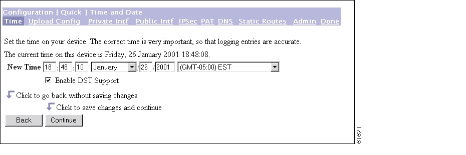
The Manager displays the Configuration | Quick | Time and Date screen.
Figure 3-3 VPN 3002 Configuration | Quick | Time and Date Screen.
This screen lets you set the time and date on this device.
Step 1
–
–
–
Step 2
Uploading an Existing Configuration File
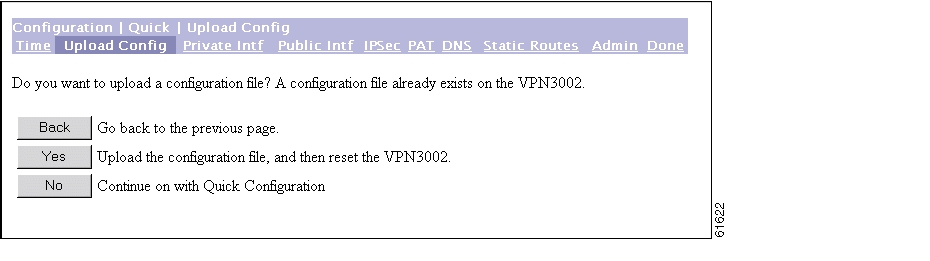
The Manager displays the Configuration | Quick | Upload Config screen.
Figure 3-4 VPN 3002 Configuration | Quick | Upload Config Screen
This feature enables you to use HTTP or HTTPS to transfer (upload) configuration files from your PC, or from a system accessible to your PC, to the VPN 3002 flash memory.
Step 1
Step 2
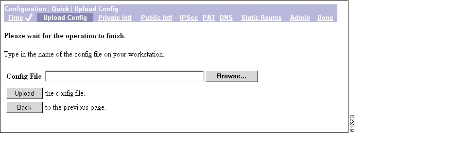
The Manager displays the Configuration | Quick | Upload Config | Browse screen.
Figure 3-5 VPN 3002 Configuration | Quick | Upload Config | Browse Screen
.
Step 1
Step 2
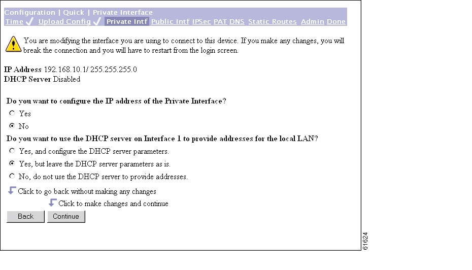
Configuring the Private Interface
The VPN 3002 Configuration | Quick | Private Interface screen displays.
Figure 3-6 Configuration | Quick | Private Interface Screen
This screen lets you configure the VPN 3002 private interface, which is the interface to your private network (internal LAN).
The screen displays the current configuration settings.
Note
Caution
Step 1
Step 2
Step 3
Configuration | Quick | Private Interface | Address
The Configuration | Quick | Private Interface | Address screen lets you enter a new IP address and subnet mask for the private interface.
Figure 3-7 Configuration | Quick | Private Interface | Address Screen
Step 1
192.168.12.34). Be sure no other device is using this address on the network.Step 2
255.255.255.0). The Manager automatically supplies a standard subnet mask appropriate for the IP address you just entered. For example, an IP address of192.168.12.34is a Class C address, and the standard subnet mask is255.255.255.0. You can accept this entry or change it.Step 3
Click Back if you don't want to save your changes. You return to the Configuration | Quick | Private Interface screen.
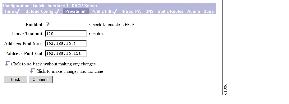
Configuration | Quick | Private Interface | DHCP Server
The Configuration | Quick | Private Interface | DHCP Server screen lets you enable and configure the VPN 3002 to serve as a Dynamic Host Configuration Protocol (DHCP) server for the private network.
The DHCP server for the Private interface lets IP hosts in its network automatically obtain IP addresses from a limited pool of addresses for a fixed length of time, or lease period. Before the lease period expires, the VPN 3002 displays a message offering to renew it. If the lease is not renewed, the connection terminates when the lease expires, and the IP address becomes available for reuse. Using DHCP simplifies configuration since you do not need to know what IP addresses are considered valid on a particular network.
Figure 3-8 Configuration | Quick | Private Interface | DHCP Server Screen
Step 1
Step 2
The Lease Timeout period you configure applies only when the tunnel to the VPN Concentrator is established. When the tunnel is not established, the Lease Timeout period is 5 minutes.
Step 3
Step 4
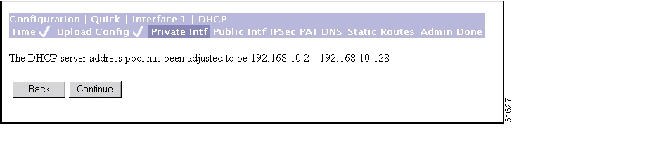
Private Interface | DHCP server address pool screen.Figure 3-9 Configuration | Quick | Private Interface | DHCP Server Address Pool Screen
This screen confirms the DHCP server address pool range you entered.
Step 5
Step 6
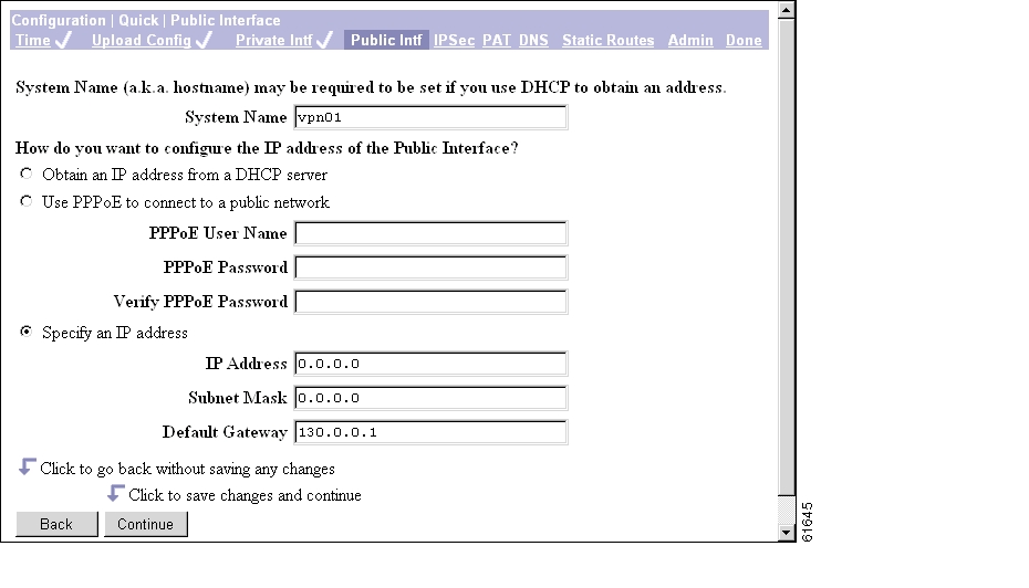
Configuring the Public Interface
The Manager displays the Configuration | Quick | Public Interface screen.
Figure 3-10 Configuration | Quick | Public Interface Screen
The public interface can obtain an IP address in one of three ways: using DHCP, PPPoE, or by static addressing. You configure one of these methods; depending on the method you choose, complete
Step 2, or Steps 3 and 4, or Steps 5-8.
Step 1
Step 2
Step 3
Step 4
Step 5
Step 6
Step 7
Step 8
To specify no default gateway—which means the VPN 3002 drops unrouted packets—leave this field at 0.0.0.0.
Step 9
See the sections that follow for more information about DHCP, PPPoE, and static addressing.
DHCP
Dynamic Host Configuration Protocol (DHCP) is a communications protocol that lets IP hosts in its network automatically obtain IP addresses from a limited pool of addresses for a fixed length of time, or lease period. Using DHCP simplifies configuration since you can manage the assignment of IP addresses from a central point. You do not need to manually enter an IP address for the public interface, and you do not need to know what IP addresses are considered valid on a particular network.
The DHCP server for the Public interface resides on the public network.
PPPoE
PPP over Ethernet (PPPoE) is a proposal that specifies how a network client interacts with a service provider's equipment, such as a broadband modem—xDSL, cable, or wireless—to achieve access to high-speed data networks. It relies on the Ethernet and PPP standards. It includes an authentication strategy that requires a username and password to create a PPPoE session on the VPN 3002.
If a PPPoE session fails due to a PPP authentication failure, the VPN 3002 does not attempt a new session until 30 seconds have passed.
Specify an IP address
This option enables you to set a static IP address, subnet mask, and default gateway for the public interface.
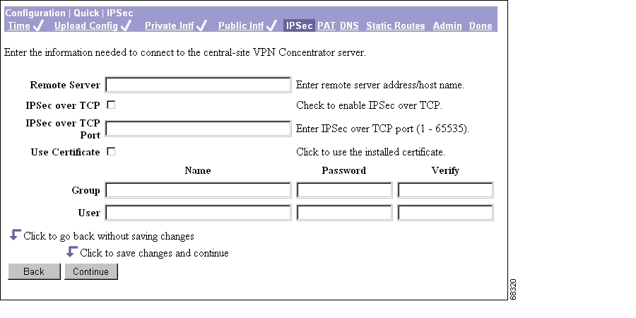
Configuring IPSec
After you click Continue to apply your changes to the Public Interface parameters, the Manager displays the Configuration | Quick | IPSec screen.
Figure 3-11 Configuration | Quick | IPSec Screen
This screen lets you configure the IPSec parameters. IPSec is the protocol that enables the VPN 3002 to connect to the VPN Concentrator over a secure VPN tunnel. The VPN 3002 can also establish IPSec tunnels to other IPSec security gateways, including the Cisco PIX firewall, and Cisco IOS routers.
Step 1
VPN 3002 hardware client connects. Note that to enter a hostname, a DNS server must be configured.Step 2
Step 3
Note
Step 4
Step 5
Step 6
Step 7
Step 8
Step 9
Step 10
Step 11
Note
Step 12
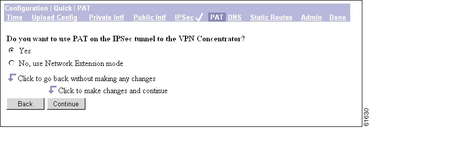
Configuring PAT or Network Extension Mode
The Manager displays the Configuration | Quick | PAT screen.
Figure 3-12 Configuration | Quick | PAT Screen
You use this screen to configure this VPN 3002 to use either PAT or Network Extension mode.
Step 1
Step 2
See the sections below for more information about PAT and Network Extension mode.
Online Technical Snapshot Explains PAT and Network Extension Modes
To view a brief interactive multimedia piece that explains the differences between the two modes, go to this url:
http://www.cisco.com/mm/techsnap/VPN3002_techsnap.html
Your web browser must be equipped with a current version of the Macromedia Flash Player to view the content. If you are unsure whether your browser has the most recent version, you may want to download and install a free copy from:
http://www.macromedia.com/shockwave/download/index.cgi?P1_Prod_Version=ShockwaveFlash
Client Mode (PAT)
Client mode, also called Port Address Translation (PAT) mode, isolates all devices on the VPN 3002 private network from those on the corporate network. In PAT mode:
•
•
All traffic from the private network appears on the network behind the central-site VPN Concentrator (the IKE peer) with a single source IP address. This IP address is the one the central-site VPN Concentrator assigns to the VPN 3002. The IP addresses of the computers on the VPN 3002 private network are hidden. You cannot ping or access a device on the VPN 3002 private network from outside of that private network, or directly from a device on the private network at the central site.
Client Mode with Split Tunneling
You assign the VPN 3002 to a client group on the central-site VPN Concentrator. If you enable split tunneling for that group, IPSec and PAT are applied to all traffic that travels through the VPN 3002 to networks within the network list for that group behind the central-site VPN Concentrator.
Traffic from the VPN 3002 to any destination other than those within the network list for that group on the central-site VPN Concentrator travels in the clear without applying IPSec. NAT translates the network addresses of the devices connected to the VPN 3002 private interface to the assigned IP address of the public interface and also keeps track of these mappings so that it can forward replies to the correct device.
The network and addresses on the private side of the VPN 3002 are hidden, and cannot be accessed directly.
VPN Concentrator Settings Required for PAT
For the VPN 3002 to use PAT, you must meet these requirements for the central-site VPN Concentrator.
1.
2.
3.
4.
Network Extension Mode
Network Extension mode allows the VPN 3002 to present a single, routable network to the remote private network over the VPN tunnel. IPSec encapsulates all traffic from the VPN 3002 private network to networks behind the central-site VPN Concentrator. PAT does not apply. Therefore, devices behind the VPN Concentrator have direct access to devices on the VPN 3002 private network over the tunnel, and only over the tunnel, and vice versa. The VPN 3002 must initiate the tunnel, but after the tunnel is up, either side can initiate data exchange.
In this mode, the central-site VPN Concentrator does not assign an IP address for tunneled traffic (as it does in Client/PAT mode). The tunnel is terminated with the VPN 3002 private IP address (the assigned IP address). To use Network Extension mode, you must configure an IP address other than the default of 192.168.10.1 and disable PAT.
In Network Extension mode, the VPN 3002 automatically attempts to establish a tunnel to the VPN Concentrator. However, if you enable interactive unit authentication in either Client or Network Extension mode, the tunnel establishes when you perform the following steps.
Step 1
Step 2
Step 3
Alternatively, you can initiate a tunnel by clicking Connect Now on the in the Monitoring | System Status screen.
Network Extension Mode per Group
VPN Concentrator software versions 3.6 and later let a network administrator restrict the use of network extension mode. On the VPN Concentrator, you enable network extension mode for VPN 3002 hardware clients on a group basis.
Note
Network Extension Mode with Split Tunneling
You always assign the VPN 3002 to a client group on the central-site VPN Concentrator. If you enable split tunneling for that group, IPSec operates on all traffic that travels through the VPN 3002 to networks within the network list for that group behind the central-site VPN Concentrator. PAT does not apply.
Traffic from the VPN 3002 to any other destination than those within the network list on the central-site VPN Concentrator travels in the clear without applying IPSec. NAT translates the network addresses of the devices on the VPN 3002 private network to the address of the VPN 3002 public interface. Thus the network and addresses on the private side of the VPN 3002 are accessible over the tunnel, but are protected from the Internet, that is, they cannot be accessed directly.
VPN Concentrator Settings Required for Network Extension Mode
For the VPN 3002 to use Network Extension mode, you must meet these requirements for the central-site VPN Concentrator.
1.
2.
3.
4.
5.
6.
Tunnel Initiation
The VPN 3002 always initiates the tunnel to the central-site VPN Concentrator. The central-site VPN Concentrator cannot initiate a tunnel to a VPN 3002. The VPN 3002 creates only one IPSec tunnel to the central-site VPN Concentrator, in either PAT or Network Extension mode. The tunnel can support multiple encrypted data streams between users behind the VPN 3002 and the central site. With split tunneling enabled, it can also support multiple unencrypted data streams to the internet.
In PAT mode, the tunnel establishes when data passes to the VPN Concentrator, or when you click Connect Now in the Monitoring | System Status screen.
In Network Extension mode, the VPN 3002 automatically attempts to establish a tunnel to the VPN Concentrator.
Tunnel Initiation with Interactive Unit Authentication
In either Client or Network Extension mode, when you enable interactive unit authentication, the tunnel establishes when you perform the following steps.
Step 1
Step 2
Step 3
Refer to the section, "Logging in With Interactive Unit and Individual User Authentication," in
Chapter 1 of the VPN 3002 Hardware Client Reference for detailed instructions.Alternatively, you can click Connect Now on the in the Monitoring | System Status screen, after which the system prompts you to enter the username and password for the VPN 3002. Refer to the section, Monitoring | System Status in the "Monitoring" chapter of the VPN 3002 Hardware Client Reference for detailed instructions.
Data Initiation
After the tunnel is established between the VPN 3002 and the central-site VPN Concentrator, the VPN Concentrator can initiate data exchange only in Network Extension mode with all traffic travelling through the tunnel. If you want the tunnel to remain up indefinitely, you should configure the VPN 3002 for Network Extension mode and not use split tunneling.
Table 3-1 summarizes instances in which the VPN 3002 and the central-site VPN Concentrator can initiate data exchange.
Table 3-1 Data Initiation: VPN 3002 and Central-Site VPN Concentrator
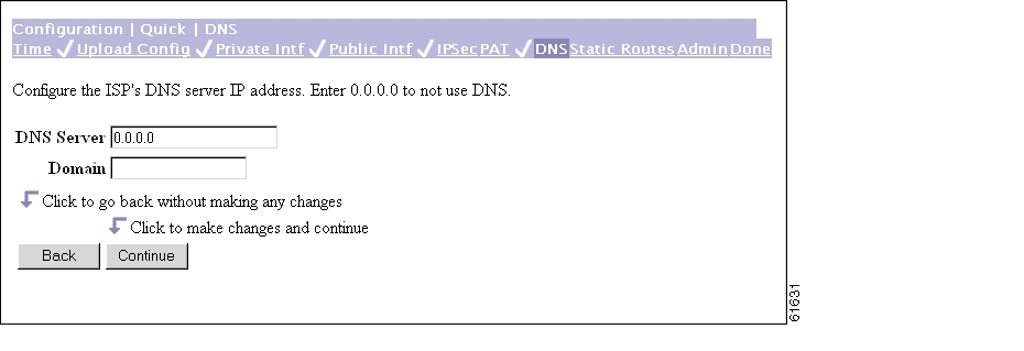
Configuring DNS
The Manager displays the Configuration | Quick | DNS screen.
Figure 3-13 Configuration | Quick | DNS Screen
This screen lets you specify a Domain Name System (DNS) server for your local ISP, which lets you enter Internet hostnames (for example,
mail01) rather than IP addresses for servers as you configure and manage the VPN 3002. While hostnames are easier to remember, using IP addresses avoids problems that might occur with the DNS server offline or congested. If you use a hostname to identify the central-site VPN Concentrator, you must configure a DNS server on the VPN 3002 (see Configuration | System | Servers | DNS).
Step 1
Step 2
Step 3
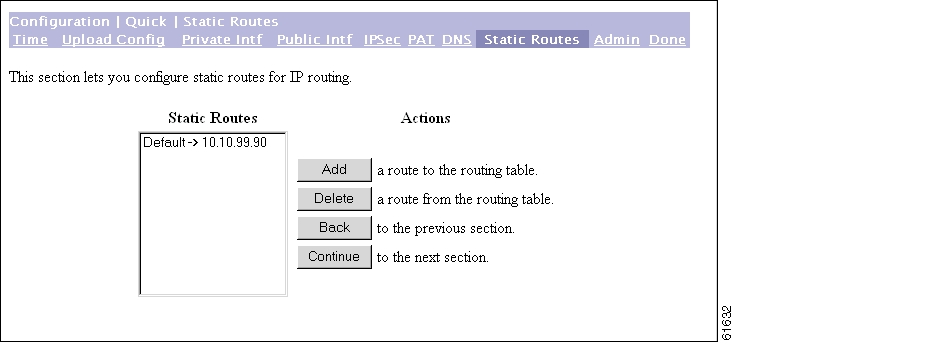
Configuring Static Routes
The Manager displays the Configuration | Quick | Static Routes screen. The Static Routes list shows manual IP routes that have been configured. The format is [destination network address/subnet mask -> outbound destination].
Figure 3-14 Configuration | Quick | Static Routes Screen
You use this screen to add or delete static routes for IP routing.
Step 1
Step 2
Step 3
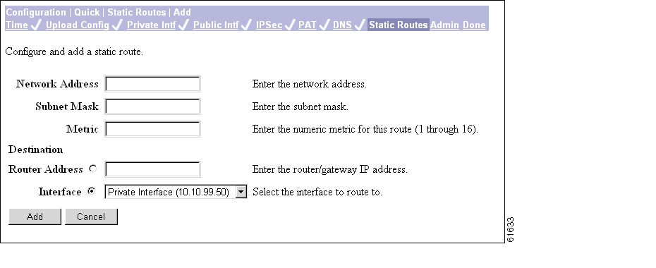
Adding a Static Route
This screen lets you add a new static route to the IP routing table.
Figure 3-15 Configuration | Quick | Static Routes | Add Screen
Step 1
Step 2
The Manager automatically supplies a standard subnet mask appropriate for the IP address you just entered. For example, the IP address 192.168.12.0 is a Class C address, and the standard subnet mask is 255.255.255.0. You can accept this entry or change it.
Step 3
Step 4
For Router Address, enter the IP address of the specific router or gateway to which to route these packets; that is, the IP address of the next hop between the VPN 3002 and the packet's ultimate destination. Use dotted decimal notation; for example, 10.10.0.2.
For Interface, click the drop-down menu button and select a configured VPN 3002 interface as the outbound destination.
Step 5
To discard your entry, click Cancel. The Manager returns to the Configuration | Quick | Static Routes screen, and the Static Routes list is unchanged.
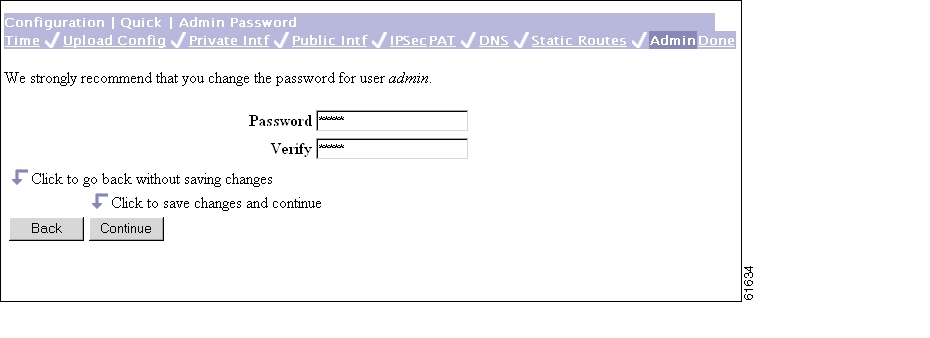
Changing admin Password
The Manager displays the Configuration | Quick | Admin Password screen.
Figure 3-16 Configuration | Quick | Admin Password | Screen
This screen lets you change the password for the admin administrator user. For ease of use during startup, the default admin password supplied with the VPN 3002 is also admin. Since the admin user has full access to all management and administration functions on the device, we strongly recommend you change this password to improve device security. You can further configure all administrator users on the regular Administration | Access Rights | Administrators Manager screen.
Step 1
W8j9Haq3. (The field shows only asterisks.)Step 2
Step 3
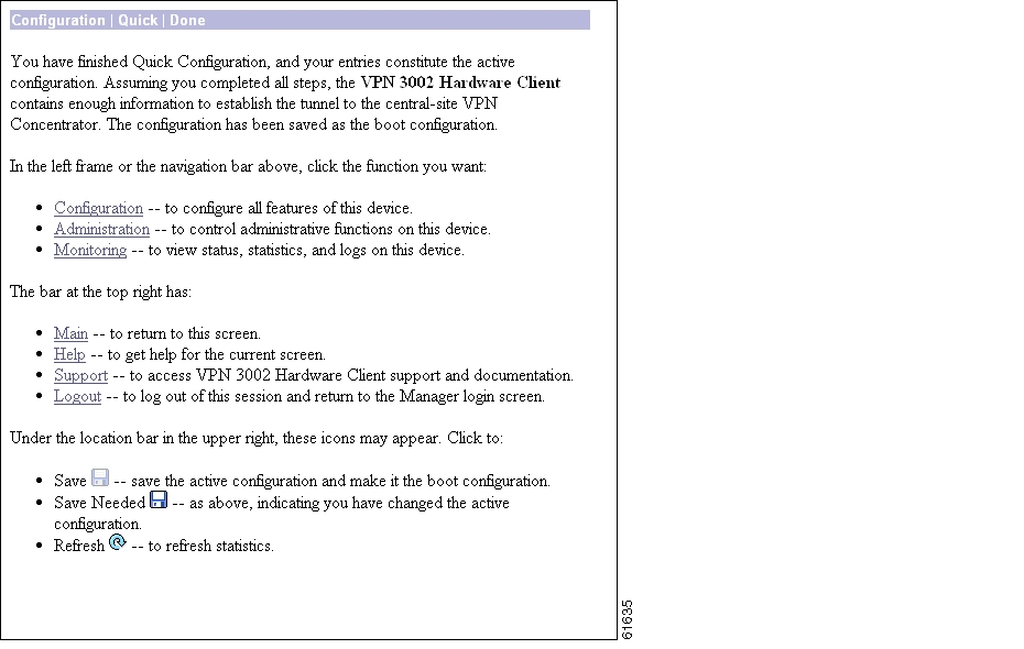
Finishing Quick Configuration
The Manager displays the Configuration | Quick | Done screen.
Figure 3-17 Configuration | Quick | Done Screen
You have finished quick configuration, and your entries constitute the active or running configuration. This configuration has now been saved as the boot configuration. The VPN 3002 now has enough information, and it is operational. The VPN 3002 can now establish a secure VPN tunnel to the central-site VPN Concentrator.
What Next?
Now that the VPN 3002 is operational, you can:
•
•
Using Other VPN 3002 Hardware Client Manager Functions
To use other VPN 3002 Hardware Client Manager functions, click the section you want in the left frame of the Manager window or on the Manager toolbar in the top frame of the Manager window.
•
•
•
•
•
•
•
•
For details on the frames, functions, and icons in the Manager window, see the next section, " Understanding the VPN 3002 Hardware Client Manager Window."
For details on the VPN 3002 hardware, all the functions available in the VPN 3002 Hardware Client Manager, or using the command-line interface, refer to the VPN 3002 Hardware Client Reference (online only).
Understanding the VPN 3002 Hardware Client Manager Window
The VPN 3002 Hardware Client Manager window on your browser consists of three frames—top, left, and main—and it provides helpful messages and tips as you move the mouse pointer over window items. The title bar and status bar also provide useful information.
Figure 3-18 VPN 3002 Hardware Client Manager Window
![]()
![]()
![]()
![]()
![]()
![]()
![]()
![]()
Posted: Fri Feb 18 08:48:23 PST 2005
All contents are Copyright © 1992--2005 Cisco Systems, Inc. All rights reserved.
Important Notices and Privacy Statement.