|
|

Table Of Contents
Cisco Network-Based Security Services Solution 2.0
Firewall Services for MPLS VPNs Using the FWSM
IPSec Aggregation Using the VPNSM
Combined IPSec Aggregation and Firewall Service
Verifying the Cisco Network-Based Security Services Solution
Verifying the IPSec VPN Service
Cisco Network-Based Security Services Solution 2.0
Version History
1
10/22/2004
This document was created.
2
11/4/2004
Additional comments incorporated.
Executive Summary
The Cisco Network-Based Security Services Solution provides network-based IPSec termination on Multiprotocol Label Switching Virtual Private Network (MPLS VPN) networks and integrates firewall services using the Firewall Services Module (FWSM). This solution provides firewall-protected Internet access for on-net and off-net VPN sites at the network edge. This is a network-based firewall solution, with the firewall on the edge of the core network (as opposed to a customer premises equipment (CPE)-based firewall); this network design centralizes network administration and simplifies CPE requirements.
This document contains the following sections:
•
Overview
•
•
Overview
This section provides an overview of Cisco Network-Based Security Services Solution 2.0. It is divided into the following subsections:
•
•
Technologies
This section contains brief descriptions of the following major technologies involved in this solution:
•
•
Firewalls
Firewalls are networking devices that control access to private networks by monitoring and filtering traffic passing across a network boundary. They are positioned at network entrance points, typically at the border between an internal network and an external network, such as the Internet. Firewalls are also used to control access to specific parts of networks.
For more information on firewalls, see the Catalyst 6500 Series Switch and Cisco 7600 Series Router Firewall Services Module Configuration Guide, 2.2.
IPSec
IPSec is an encryption method used to transmit data securely across shared networks. IPSec is a framework of open standards that provides data confidentiality, data integrity, and data authentication between participating peers at the network layer.
For a detailed introduction to IPSec, see the previous version of this solution, Introduction to the Cisco Network-Based IPSec VPN Solution Release 1.5.
MPLS
Multiprotocol Label Switching (MPLS) is a high-performance packet-forwarding technology that integrates the performance and traffic-management capabilities of data link layer (Layer 2) switching with the scalability, flexibility, and performance of network layer (Layer 3) routing.
MPLS appends labels to the original data frames, and MPLS nodes switch the packets based on the labels. Several label distribution methods are available, including two that are relevant for this solution: LDP (RFC 3031) and MP-BGP (RFC 2547).
MPLS VPNs run between provider edge (PE) and customer edge (CE) routers. MPLS VPNs maintain a discrete routing table for each VPN, known as a VPN routing and forwarding instance (VRF).
A PE-CE interface can be marked as belonging to a particular VRF by configuration. All traffic on that interface, both incoming and outgoing, is treated as part of the VPN.
A VRF includes routing and forwarding tables and rules that define the VPN membership of customer devices attached to PE routers. A VRF consists of the following:
•
•
•
•
VPN routing information is stored in the IP routing table and the CEF table for each VRF. A separate set of routing and CEF tables is maintained for each VRF. These tables prevent information from being forwarded outside a VPN and also prevent packets that are outside a VPN from being forwarded to that particular VPN.
For more information on MPLS, see the "Multiprotocol Label Switching Overview" chapter of the Cisco IOS Switching Services Configuration Guide, Release 12.3.
Network Architecture
Cisco Network-Based Security Services Solution 2.0 builds on its earlier phases by providing additional services and increasing the scalability and performance of the deployments. This phase of the solution introduces the Virtual Firewall Service and VRF-Aware IPSec VPN service on the Cisco 6500/7600. It provides means for service providers (SPs) to integrate these services with their existing VPN networks. Both IP/MPLS-based and Layer 2-based VPN networks are supported.
MPLS-based VPN technology allows SPs to connect enterprise sites or a shared network through a public network and maintain the same security and service levels as those provided by private networks. The public network in this case is the SP's network, consisting of provider edge (PE) and provider core (P) routers.
To form a seamless VPN network on a per-enterprise basis, each customer site is connected to the provider core network through one or more PE routers using one or more customer edge (CE) routers. Sites are then interconnected through an MPLS backbone to create an MPLS VPN. If all interconnected sites belong to the same customer network, an MPLS VPN intranet is created. If the interconnected sites belong to different customer networks (one of these networks may be the public Internet), an MPLS VPN extranet is created.
This model addresses sites directly connected to the VPN provider, but it does not address the needs of a remote site not that connects over the Internet but that is not serviced by the same provider. IPSec is used to provide data security across public networks. This solution integrates IPSec capabilities with the existing VPN infrastructure (IP, MPLS, or Layer 2) to provide a complete portfolio of VPN capabilities. The IPSec sessions are terminated at the edge of the VPN backbone and are mapped into their respective VPNs.
The focus of the IPSec VPN portion of this solution is to provide a scalable solution to terminate and map IPSec sessions into VPNs.
The focus of the Virtual Firewall portion of this solution is to provide a scalable, network-based firewall service that can be integrated into existing VPN networks and perform the task of traditional, standalone firewalls. The virtual firewall service can provide firewalling for any shared services access (such as Internet access or Voice over IP (VoIP) gateways), or it can be used to control access between sites.
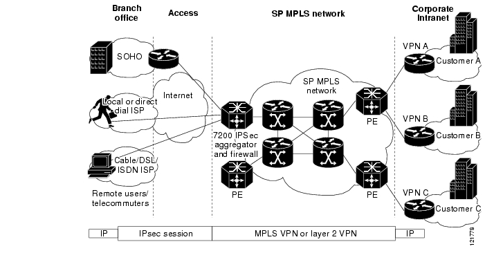
Figure 1 shows the generic network topology of Cisco Network-Based Security Services Solution 2.0.
Figure 1 Cisco Network-Based Security Services Topology
IPSec-to-MPLS mapping is performed by VRF-aware Internet Key Exchange (IKE) based on a number of configurable criteria (group ID, IP address, fully-qualified domain name (FQDN), etc.) All off-net customers (both remote sites and individual users) peer to a single public IP address on the aggregator, and IKE then maps them to the appropriate VPN.
Each VPN is associated with a VRF. Routes to the remote sites or users are added to the VRF routing table (either statically or dynamically). Because IPSec does not carry multicast traffic, GRE tunnels are defined on the CPE and the IPSec aggregator to transport the routing protocols. For remote users, Remote Route Injection (RRI) can be used to populate the route to the remote IP address in the appropriate VRF.
The PE router on the MPLS network redistributes static and connected routes to the VPN. Multiprotocol Border gateway Protocol (MBGP) advertises the VPN IPv4 prefixes to the remote CPEs that contain the same VPN.
Cisco Network-Based Security Services Solution 2.0 integrates virtualized firewall services using the FWSM. When firewall services are employed, a default route that advertises Internet reachabilitiy is injected into the VPN routing tables. This default route ensures that all VPN users (at both on-net and off-net sites) are required to pass through the firewall to enter or exit the Internet.
Because the FWSM blade is not VRF aware, 802.1Q trunks are used to map the VRFs to the virtual firewalls.
Hardware Components
This section describes the following hardware used in the solution:
•
•
•
Security Services PE
Phase 1.5 of the solution introduced IPSec VPN service integration on the Cisco 7200 series router. Phase 2.0 of the solution introduces the Virtual Firewall and VRF-Aware IPSec VPN services on the Cisco 6500 and 7600 series routers with the Supervisor Engine 720 (Sup720). These services require the Firewall Service Module (FWSM) and VPN Services Module (VPNSM) service modules respectively. Up to four FWSM blades per chassis but only one VPNSM blade (together or independently) are supported with this solution.
Sup720
The Sup720 delivers scalable performance, a rich set of IP features, and strong security features. The Sup720 integrates a high-performance 720-Gbps crossbar switch fabric with a forwarding engine in a single module, delivering 40 Gbps of switching capacity per slot.
The MSFC3 is an integral part of the Supervisor Engine 720, providing high-performance, multilayer switching and routing intelligence. Equipped with a high-performance processor, the MSFC runs Layer 2 protocols on one CPU and Layer 3 protocols on the second CPU. These include routing protocol support, Layer 2 protocols (Spanning Tree Protocol and VLAN Trunking Protocol, for example), multimedia services, and security services.
The Supervisor Engine 720 features the Policy Feature Card3 (PFC3), which is field-upgradable and equipped with a high-performance ASIC complex supporting a range of hardware-based features. The PFC3 supports routing and bridging, QoS, and multicast packet replication, and processes security policies such as access control lists (ACLs).
The specific engine used for this solution is the WS-SUP720-3BXL, which uses the PFC3BXL version of the PFC3.
For more information on the Sup720, see the Cisco Catalyst 6500 Series Supervisor Engine 720.
FWSM
The FWSM 2.2 is a high-performance, stateful firewall module that installs in the Catalyst 6500 series switches and the Cisco 7600 series routers. It supports up to 100 virtual firewalls using PIX version 6.2. The FWSM uses virtual local area networks (VLANs) as interfaces that connect to the virtual firewalls.
The virtual firewalls can be configured for either routed (Layer 3) or transparent (Layer 2) mode. The routed mode can perform Network Address Translation (NAT)/Port Address Translation (PAT), and it can support up to 256 interfaces per context (with a maximum of 1000 total interfaces). The transparent mode connects two segments of the same network on its inside and outside ports, with each port being on a different VLAN. Transparent mode does not perform NAT, and supports only two interfaces. Transparent mode should be used when running routing protocols.
For more information on the FWSM, see the Catalyst 6500 Series Switch and Cisco 7600 Series Router Firewall Services Module Configuration Guide, 2.2.
RADIUS Server
Any RADIUS server that supports Cisco attribute/value (AV) pairs can be used in this solution. The RADIUS server authenticates and authorizes remote access clients. The preshared key and Mode-config parameters (such as IP address pool name, and split tunneling ACL) can be downloaded from the RADIUS server. The RADIUS server can also perform user authentication.
RSA Server
The RSA server is an optional network component for this solution. It is used when two-factor secure ID-based authentication is required. The RSA server can be installed on the SP management network for local (Authentication, Authorization and Accounting) AAA, or it can be installed on the customer premises for proxy authentication.
VPNSM
The Cisco IPSec VPN Services Module is a high-speed module for the Cisco Catalyst 6500 Series Switch and the Cisco 7600 Series Internet Router that provides infrastructure-integrated IPSec VPN services to meet the need for ubiquitous connectivity and increased bandwidth requirements. For more information on the VPNSM, see the Cisco 7600/Catalyst 6500 IPSec VPN Services Module.
Software Requirements
This section describes the following software requirements for the solution:
•
•
FWSM
Version 2.2 of the FWSM software introduces support for virtual firewalls.
Cisco Unity VPN Client
The Cisco Unity VPN Client is the only VPN client that is supported as part of this solution. The client is supported on the following systems:
•
•
•
•
Cisco Unity VPN Client Release 4.0 or higher is recommended for this solution, although earlier versions are supported.
VPNSM
The PE router must be running Cisco IOS Release 12.2(18)XD1 for the VPNSM to support VRF-aware IPSec. The VPNSM relies on the Cisco IOS software and does not run its own software.
Deployment Models
The following deployment models are described in this solution:
•
•
•
Deploying Virtual Firewall Service for Internet and Shared Services
The FWSM can be deployed to support a number of applications. Virtualization allows it to be used as a network-based firewall supporting numerous VPN customers. The following are some of the applications it can support:
•
•
For example, if a managed voice service is based on H.323, the virtual firewall performs NAT on the necessary embedded IP addresses in the H.225 and H.245 control streams and dynamically allocates the negotiated H.245 and Real-Time Protocol (RTP)/RTP Control Protocol (RTCP) connections.
•
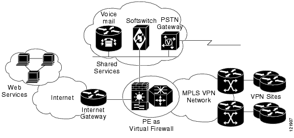
Figure 2 shows a sample topology for a network offering virtual firewall service for both Internet access and shared services.
Figure 2 Virtual Firewall Service for Internet and Shared Services
The firewall solution supports a number of features, such as network access control, stateful failover, logging access control, NAT, customer management of firewall policies, protocol fixups, and numerous filtering options. These features allow the firewall to be flexibly deployed to protect private customer networks from external threats.
For information on how to deploy virtual firewall services, see the " Firewall Services for MPLS VPNs Using the FWSM" section of this document.
Integrating IPSec VPNs and MPLS VPNs
Previous phases of this solution introduced the concept of network-based IPSec VPN services. In addition to providing this same level of feature support, phase 2.0 of this solution provides increased scale and performance by using the VPNSM on the Cisco 7600 series. The solution can securely connect remote sites and clients with existing VPN services, such as MPLS VPNs and Layer 2 VPNs. The solution also supports the termination of multiple customers on the same device, and it provides the ability to seamlessly map these customers into VPNs.
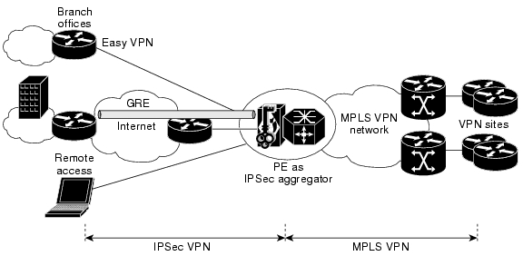
Figure 3 shows the topology of a network that integrates IPSec VPNs with MPLS VPNs.
Figure 3 Integrated IPSec VPNs and MPLS VPNs
The solution enables SPs to offer a wide variety of security options, including site-to-site native IPSec, Easy VPN client for smaller sites, Generic Routing Encapsulation (GRE) with dynamic routing for larger locations, and VPN clients for PCs. The solution also supports many key management options including preshared keys, RSA keys and certificates, and RADIUS-based AAA services for VPN clients.
Although such services are typically deployed with MPLS VPN service, this solution can be integrated with other forms of transport, such as IP and Layer 2 networks. In each of these cases, the sessions are mapped to VRFs on the PE, and then connected to the customer network by non-MPLS VPN mechanisms (such as GRE when using IP, and PVCs or VLANs when using Layer 2 transports).
For information on how to integrate IPSec VPN and MPLS VPN services, see the " IPSec Aggregation Using the VPNSM" section of this document.
Integrating Virtual Firewall and IPSec VPN Services
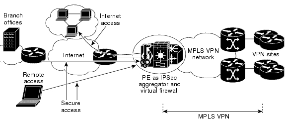
To fully take advantage of this solution's capabilities, SPs can now seamlessly combine virtual firewall and IPSec VPN services on a single platform and offer them together as a comprehensive service. The virtual firewall functionality protects customer VPNs from public networks, and the IPSec VPN service provides comprehensive, secure remote access. This allows the SP to extend its VPN footprint beyond the boundaries of its physical network.
This combined service is also useful for Application Service Providers (ASPs) who work with customers that maintain server farms that are separated from their central network by VLANs and protected by virtual firewalls. Additionally, the IPSec service can be used to provide secure connectivity into the customer applications and services.
Figure 4 shows a network topology that integrates virtual firewall and IPSec VPN services.
Figure 4 Integrated Virtual Firewall and IPSec VPN Services
Features
The following sections describe the feature support of the Cisco network-based security services solution:
•
Virtual Firewall Features
The following virtual firewall features are supported by the Cisco Virtual Firewall solution:
•
Multiple Contexts
Support for multiple contexts is the key feature that enables SPs to provide Virtual Firewall service. Each security context can be thought of as a self-contained firewall, servicing a unique enterprise. Each context can be configured with its own set of policies without any dependencies on other contexts. The contexts are configured in the system space of the firewall module. The SP can use the system configuration space to add contexts, assign interfaces, allocate resources, and manage these contexts. The system space by itself has no network connectivity and for this purpose uses a special context called the administrative context.
The following configuration example shows a basic system configuration with two contexts—an administrative context named "admin" and a customer context named "red." The administrative context is allocated two VLANs, 10 and 11, and the customer context "red" is allocated VLANs 101, 151, 152 and 200.
admin-context admincontext adminallocate-interface vlan10-vlan11config-url disk:/admin.cfg!context redallocate-interface vlan101allocate-interface vlan151-vlan152allocate-interface vlan200config-url disk:/red.cfg
Note
Context Access Control
After the security contexts have been defined, it is important to restrict access to the contexts. Individual customers can manage their own contexts using Telnet or Secure Shell (SSH) from the inside. Once logged in they do have the ability to make changes to their own system context (policies, ACLs, fixups and so on), but they cannot access any other contexts or the system configuration space. Access to the customer contexts is controlled using AAA authentication.
The following configuration example configures the context "red" for Telnet access with user authentication using RADIUS. The RADIUS server at IP address 172.16.100.1 is accessible by way of the inside interface called "redin."
aaa-server red-auth protocol radiusaaa-server red-auth max-failed-attempts 3aaa-server red-auth deadtime 10aaa-server red-auth (redin) host 172.16.100.1 red123 timeout 10aaa authentication telnet console red-authResource Limiter
The Resource Limiting feature allows a SP to control the maximum amount of resources that each customer context can use. Configuring resource limits is important because without limits, a few contexts can use all the available resources and affect service to the other contexts. Resource limits can be set for the following resources:
•
•
•
•
•
•
•
•
The resource limits are set in the system configuration space by defining resource classes. Classes are then applied to individual contexts. Individual resources can be limited as a percentage or as an absolute value. Also, you can set limits for all the resources (aggregated) as a percentage of the total available for the device.
The following example defines a class called "gold" that limits the number of connections per second, Telnet sessions, host connections, and number of NAT translations. All the other resources are set to consume not more than 5% of the remaining bandwidth.
class goldlimit-resource Xlates 10000limit-resource Telnet 5limit-resource Hosts 500limit-resource rate Conns 20000limit-resource All 5.0%context redmember goldNetwork Access Control
Network access can be controlled either by using access lists (ACLs) or through the AAA server. ACLs are the simplest means of access control and are suitable when a policy is applied uniformly to all traffic passing through an interface. AAA is a more sophisticated mechanism and provides more granular access control along with user authentication and authorization.
By default, the firewall will not allow any traffic through unless it is explicitly permitted. For TCP/UDP-based traffic, you do not need to explicitly permit the return traffic because the firewall allows return traffic to pass through if it already has an outgoing connection state. For other traffic, an ACL must be defined to permit the return traffic. If you have a fixup configured for that protocol, you do not need to define the ACL because the firewall will maintain the state automatically. Extended ACLs can be used based on source/destination address, protocol, or port number.
When using AAA, the firewall uses a cut-through proxy to challenge the user initially at the application layer and then authenticates the user by means of RADIUS, TACACS+, or the local database. The traffic that needs to be authenticated can be identified using authentication rules or by matching an ACL name. Authentication rules can include only one source and destination subnet and service, while an ACL can include many entries. Although network access authentication can be configured for any protocol or service, only HTTP, Telnet, or FTP can be used for actual authentication. A user must first authenticate using one of these services before other traffic that requires authentication is allowed.
For Telnet and HTTP, the firewall module generates an authentication prompt. If the destination server also has its own authentication, the user is prompted to enter another username and password. For FTP, the syntax for entering the username is as follows: firewall_username@ftp_username. The password should be defined in a similar format.
While using RADIUS, authorization can be simultaneously performed with user authentication. An ACL name or a dynamic ACL can be downloaded from the RADIUS server, and the firewall would check the user traffic against the ACL to determine if the traffic is permitted or denied. For example, if you are using CiscoSecure ACS, the ACL name could be defined either under each user (per-user ACL) or under a group if a set of users shares the same ACL (per-group ACL).
If accounting is enabled, the firewall sends the accounting information to the RADIUS server. A start record is sent only if the user has successfully authenticated. A start/stop accounting record provides information such as username and duration of each session.
The following configuration example specifies that all HTTP traffic received by the "redin" interface (matching auth_check) is to be authenticated, and only traffic destined for the host 10.1.50.100 is accounted using the RADIUS server, "red-radius":
access-list auth_check extended permit tcp any any eq wwwaccess-list acct_check extended permit tcp any host 10.1.50.100 eq wwwaaa-server red-radius (redin) host 172.16.100.1 red123 timeout 10aaa authentication match auth_check redin red-radiusaaa accounting match acct_check redin red-radiusNetwork Address Translation
The solution allows numerous options for creating address translations for both incoming and outgoing traffic. Network address translation (NAT) is mandatory when VPN traffic is accessing global or shared networks because of the potential for overlapping addresses across VPNs. The following is partial list of the NAT options available:
•
•
•
•
Protocol Fixups
Specialized protocol and application inspections are known as fixups because the firewall inspects and alters the application layer packet. Fixups are used for applications that embed IP addresses in the payload or that open multiple ports dynamically. When protocol inspection is enabled for an application that embeds IP addresses, the firewall translates the embedded addresses and updates any checksum or other fields that are affected by the translation. When protocol inspection is enabled for an application that uses dynamic ports, the firewall monitors the session to identify the dynamic port assignments, and permits traffic on these ports for the duration of the session.
Up to 32 fixups can be configured per context, including any fixups that are enabled by default. Fixups can be configured for protocols such as FTP, HTTP, ICMP, MGCP, SIP, and SKINNY. For a complete list of protocols, their default settings, and compatibility with NAT please refer to: http://cco/en/US/products/hw/switches/ps708/products_module_configuration_guide_chapter09186a00802010c1.html
The following configuration example shows how ICMP and ICMP error fixups are enabled:
fixup protocol icmpfixup protocol icmp errorThe ICMP fixup allows the firewall to maintain a state for ICMP traffic that allows it to be inspected. The fixup performs NAT and checksum modification on both the outer IP header and the payload. The firewall creates address translation entries for intermediate hops that send ICMP error messages, based on the NAT configuration.
External URL Filtering
The features already described can control user authentication and authorization but not session-layer control. For example, to restrict web usage based on the sites that users can visit, you must perform URL filtering. Filtering URLs locally on the firewall module, though supported, is not recommended because it would impact the performance of the module. The ideal way to control access to specific websites is to use external URL filtering servers. The firewall module supports two external URL filtering servers: Websense for HTTP, HTTPS and FTP filtering, and N2H2 for HTTP filtering only.
When a user issues an HTTP request, the firewall sends the request to the web server and the filtering server at the same time. If the filtering server permits the connection, the firewall allows the reply from the web server to reach the user who issued the original request. If the filtering server denies the connection, the firewall redirects the user to a block page, indicating that access was denied.
Up to four filtering servers of the same kind (Websense or N2H2) can be defined per context. The following configuration example shows how a filtering (N2H2) server is defined in the context "red" and located off the interface "dmz." It also enables URL caching. After a user accesses a site, the N2H2 server can allow the firewall to cache the source and the web server address for a certain amount of time. Then, when the user accesses the server again, the firewall does not need to consult the N2H2 server again. The size of the cache is configured to maintain 64 KB of data. Finally URL filtering is configured for all traffic coming from the IP address 172.16.0.0/16 that is destined for anywhere on the Internet.
url-server (dmz) vendor n2h2 host 10.0.1.1url-cache src_dst 64filter url http 172.16.0.0 255.255.0.0 0 0Inter/Intra-Chassis Failover
The solution supports regular failover, stateful inter-chassis failover, and stateful intra-chassis failover. You can specify the active and standby units as long as they are running the same software version and license. When the active unit fails, the standby unit changes to the active state and takes over the active unit IP addresses and MAC address. The new standby unit takes over the standby IP addresses and MAC address.
In the case of a regular failover, all active connections are dropped. Clients must reestablish connections when the new active unit takes over. In the case of the stateful failover, after a failover occurs, the connection information is available at the new active unit. The supported end-user applications are not required to reconnect and can maintain the same session. This is because during normal operation, the active unit continually passes per-connection stateful information for each context to the standby unit. The update interval is configurable, and the default is 10 seconds.
The state information passed to the standby unit includes information from NAT tables, TCP connection states, HTTP connection states, and H.323, SIP, and MGCP connection information.
The failover is achieved using two types of links:
•
•
Intra-chassis failover is useful in protecting against module failover. Other than the standard system and context configuration, this requires configuration of failover and state VLANs in the system space.
If a more redundant system is required, inter-chassis failover must be configured. This protects against both module failure and router failure. Inter-chassis configuration, as can be expected, is a little more complicated than intra-chassis failover. A trunk port should be defined between the two chassis to carry not only the customer VLANs but also the failover and state links. The spanning-tree algorithm ensures that the traffic passes through the active firewall module only.
If the primary module fails, the secondary module becomes active. If the primary router is still active all VLAN traffic destined for the firewall continues to enter the primary router. The secondary (now active) module receives and sends all the traffic over the trunk. If the entire router fails along with the firewall module (because of power failure, for example), both the router and the module fail over to their secondary units.
The firewall module can perform both unit monitoring and interface monitoring to initiate failover. The firewall monitors the other unit by monitoring the failover link. When a unit does not receive hello messages on the failover link, the unit sends an ARP request on all interfaces, including the failover interface. If the module does not receive a response on any interface, the standby unit switches to active mode and classifies the peer as failed. If the module does not receive a response on the failover link only, the unit does not failover. The failover link is marked as failed, and it should be manually restored to resume active/standby activity.
The firewall can be set to monitor individual interfaces within each context to detect failure. When a unit does not receive hello messages on a monitored interface, it runs a series of network tests (ARP, link up/down, ping, and so on) to determine if the interface has failed. If the threshold for failed interfaces is surpassed, and the standby unit has more operational interfaces, a failover occurs. Up to 250 total interfaces can be monitored across all the contexts to determine failover.
Note
IPSec Features
The following IPSec features are supported by the Cisco Network-Based Security Services solution:
•
•
•
VRF-Aware IPSec
This phase of the solution adds the key functionality of making IKE and IPSec VRF-aware on the Cisco 7600 series. The solution uses the hardware acceleration provided by the VPNSM module for all the crypto processing functions (IPSec packets, IKE crypto math, and GRE processing). The VPNSM itself is not VRF-aware; therefore, it relies on VLANs to achieve traffic separation for encrypted and decrypted packets. It has an inside interface and an outside interface that can be used to trunk VLANs into and out of the module. Typically, we define a VLAN per VRF on the MSFC for the traffic to be encrypted. The following configuration illustrates the packet flow:
interface FastEthernet3/4ip address 172.26.185.33 255.255.255.0crypto engine slot 5!interface GigabitEthernet5/1no ip addressflowcontrol receive onflowcontrol send offswitchportswitchport trunk encapsulation dot1qswitchport trunk allowed vlan 1,301,302,1002-1005switchport mode trunkspanning-tree portfast trunk!interface GigabitEthernet5/2no ip addressflowcontrol receive onflowcontrol send offswitchportswitchport trunk encapsulation dot1qswitchport trunk allowed vlan 1,1002-1005switchport mode trunkspanning-tree portfast trunk!interface Vlan301ip vrf forwarding redip address 192.168.1.1 255.255.255.0crypto map redcrypto engine slot 5In this example, VLAN301 is used as the inside VLAN, and Fast Ethernet interface 3/4 is used as the actual physical interface with outside connectivity to send and receive encrypted packets. By virtue of applying a crypto map and specifying the crypto engine module, VLAN301 becomes a special point-to-point VLAN, and it is automatically trunked to the VPNSM's inside interface, Gigabit Ethernet interface 5/1, which performs the actual encryption. The Security Associations (SA) created on the VPNSM contain the associated VLAN tag. After encryption, the packets are sent back out Gigabit Ethernet interface 5/2 to the MSFC, where they are globally routed out FastEthernet3/4.
Encrypted packets coming in on FastEthernet3/4 are dynamically sent to the VPNSM (interface Gigabit5/2) because of the crypto engine slot command. The VPNSM finds the proper SA using the SPI and decrypts the packet. It inserts the VLAN tag in the decrypted packets before forwarding it to the MSFC on interface Gigabit5/1. The packets arrive on the MSFC on VLAN301 for VRF RED and are tag-switched out to the MPLS VPN network like normal VPN packets.
Note
IPSec VPN Client Support
The Cisco IPSec VPN client is the only remote-access client supported for this solution. The VPN client supports multiple connection profiles on the clients. It supports device authentication through either of the following two methods:
•
•
It supports user authentication through XAUTH. Parameters such as IP address, WINS and DNS server IP address, and split tunneling can be pushed from the concentrator using Mode-Config. The VPN client creates at least three SAs per session:
•
•
GRE Support
GRE provides a way to encapsulate arbitrary packets inside a transport protocol. It is implemented as a virtual interface to provide a simple interface for configuration. The tunnel interface is not tied to specific transport protocols; rather, it is an architecture that is designed to provide the services necessary to implement any standard point-to-point encapsulation scheme. The VPNSM module provides on-board GRE acceleration.
Because IPSec does not support multicast traffic, it does not encrypt routing protocol updates across the IPSec tunnel. GRE provides an ideal solution because all traffic (as well as the routing protocol updates) is forwarded to the tunnel interface, and the GRE tunnel is matched against the crypto access list for encryption. Because the GRE tunnel packets are IP unicast packets that encapsulate the original IP multicast/unicast packet, IPSec can be used to encrypt the GRE tunnel packet. Also, because GRE has already encapsulated the original data packet, IPSec does not have to encapsulate the GRE IP packet in an additional IP header. Therefore, IPSec can be run in transport mode. GRE keepalives are also supported as part of the solution.
GRE keepalives are particularly important if the tunnel is created over the Internet, since without them the tunnel interface would always remain up, even if the endpoint were unreachable. The lack of keepalives can potentially lead to situations where data becomes lost in the Internet.
Note
Reverse Route Injection
Reverse Route Injection (RRI) is a feature designed to simplify network design for VPNs where there is a requirement for redundancy or load balancing. RRI works with both dynamic and static crypto maps. In the dynamic case, as remote peers establish IPSec security associations with an RRI-enabled router, a static route is created for each subnet or host protected by that remote peer. For static crypto maps, a static route is created for each destination of the extended access-list rule associated with that map (by the match address command of the crypto map).
Once routes are created, they are injected into any dynamic routing protocol and distributed as usual. This traffic flow requires IPSec to be directed to the appropriate RRI router for transport across the correct SAs to avoid IPSec policy mismatches and possible packet loss. The static routes injected into the respective VRF tables by RRI can then be redistributed into other routing protocols (such as Border Gateway Protocol (BGP) and Open Shortest Path First (OSPF)). The routes distributed can be host routes, or the routes can be summarized and redistributed.
Support for Easy VPN Client/Server
Easy VPN is the implementation of the Unity VPN Client on Cisco IOS in both server and client mode. Easy VPN client and server support in Cisco IOS VPN devices allows centrally managed IPSec policies to be pushed to the client by the server, minimizing configuration by the end user. The client CPE can be configured in either the client mode or the network extension mode.
The following is a partial list of the policies that can be pushed from the VPN concentrator to the Cisco Easy VPN client-enabled router:
•
•
•
•
•
When the client initiates a connection with the VPN device, the sequence of events that occurs between the peers consists of device authentication through IKE, followed by user authentication using XAUTH, VPN policy push (using Mode Configuration), and IPSec SA creation.
Easy VPN clients operate in two modes:
•
•
RADIUS Support for AAA
The solution supports RADIUS-based authentication and authorization for remote-access clients. RADIUS-based start/stop accounting is supported with the option of sending periodic updates. The start record supports the following attributes:
•
•
•
•
•
•
•
•
–
–
–
–
–
The key attributes to note are the VRF ID to identify the VRF or VPN to which the user belongs and the ISAKMP phase 1 ID, which shows the client group name. Other attributes include the IP address that was assigned to the client and the username used during XAUTH. The stop record consists of the following attributes:
•
•
•
•
•
Using the VRF ID and the username, the accounting records can easily be used for billing purposes. You can also set the router to send periodic updates by setting the update interval using the aaa accounting update periodic command.
The following configuration defines the ISAKMP profile:
aaa authentication login red-list group radiusaaa authorization network red-list group radiusaaa accounting network red-list start-stop broadcast group radius!crypto isakmp profile red-ravrf redmatch identity group red-clientclient authentication list red-listisakmp authorization list red-listclient configuration address respondaccounting red-listSPs can deploy either of the following two AAA models:
•
•
Note
Comprehensive Client Attributes
The solution supports a comprehensive set of attributes for the VPN clients that can be configured either locally on the router or on a RADIUS server (which provides a more scalable solution). Table 1 lists all the attributes supported.
NAT Transparency
NAT transparency support is important if clients connect from behind a NAT device. There are a number of potential incompatibilities when dealing with IPSec ESP/AH with NAT. To overcome the ESP limitations, the Cisco VPN client wraps the ESP packets within a UDP wrapper. This requires the server side to be able to strip off the UDP header and then perform decryption. The server should also be able to encapsulate the packets it encrypts with a UDP wrapper. The original ESP packet is encapsulated in a UDP header before being sent out by the client. When such a packet passes a NAT-enabled device, only the outer IP/UDP header is translated, keeping the inner ESP packet intact without any modifications. The client and server dynamically recognize that they are passing through a NAT device and negotiate using NAT transparency. Thus, this feature allows clients to connect from behind NAT devices.
Dead Peer Detection
In situations where two entities are communicating with IPSec, the link between the peers—or one of the peers itself—can fail before the IPSec SAs expire. In these situations, the remaining peer continues to send encrypted traffic via the SAs. The result is what is commonly referred to as a "black hole"; this situation persists until the IPSec SAs expire.
To avoid black-hole situations, a peer can send a keepalive message to signal that it is still reachable. But traditional IOS-style keepalives do not scale well because they are sent at periodic intervals, regardless of the level of traffic flow, and in large networks, the hub must process multiple keepalive messages from its various peers. The large number of messages is compounded by the fact that keepalive messages are tied to the IKE SA, and consequently must be handled at a process level. Therefore, a large amount of the hub's processing power is wasted on the hub site to process these keepalives, affecting the performance of the device. Dead Peer Detection (DPD) keepalive schemes provide a much more scalable alternative without impacting the failover response time.
A router that sends DPD messages uses a timer to maintain DPD status. It keeps track of time elapsed since it sent a DPD R-U-THERE message to its peer. Additionally, a passive timer (a time stamp) keeps track of the last time data was received from a given peer. If a configurable amount of time has lapsed since the last inbound data, the Cisco IOS DPD mechanism sends a DPD R-U-THERE message the next time it sends outbound IPSec data to the peer.
IPSec Idle Timeout
Because this solution may potentially deploy services to thousands of customers, it is important to maximize scalability. Users tend to keep unused VPN connections up, particularly if the user is being charged a flat rate for services. Consequently, idle SAs can prevent new sessions from connecting.
To terminate idle SAs, the idle timeout feature is implemented in phase 2.0 of this solution. The IPSec idle timeout can be applied at a global level or within each crypto map.
Global Idle Timeout
crypto IPSec security-association idle-time 3600Within the Dynamic Crypto Map for Clients
crypto dynamic-map dyna 1set security-association idle-time 7200set transform-set tset1set isakmp-profile vpn1-ezreverse-routeWithin the Static Crypto Map for Site-to-Site
crypto map vpn 10 IPSec-isakmpset peer 10.1.1.1set security-association idle-time 7200set transform-set tset1set isakmp-profile vpn1match address 101The idle timeout set within the crypto maps overrides the global setting.
Public-Key Infrastructure (PKI) Support
The solution supports the public key infrastructure (PKI) for managing digital certificates. Certificates offer a scalable and secure alternative to preshared keys, especially for large deployments. IKE can use digital signatures to scalably authenticate peer devices before setting up security associations. Without digital signatures, users must manually exchange either public keys or secrets between each pair of devices that use IPSec. However, by using digital certificates, users simply enroll each new device with a certificate authority (CA). When two devices need to communicate, they exchange certificates, and each digitally signs some data to authenticate the other. When a new device is added to the network, users simply enroll that device with a CA; none of the other devices require modification. When the new device attempts an IPSec connection, IKE automatically exchanges certificates with the peer, and the devices authenticate each other.
The following is a partial list of key features that are supported as part of this solution:
•
•
•
•
•
•
IPSec Features Not Currently Supported
The following IPSec features are supported on the Cisco 7200 but not on the Cisco 7600:
•
•
•
•
•
•
•
Design Considerations
The following sections describe some of the concepts that network administrators should consider when designing a Cisco network-based IPSec VPN solution:
•
•
•
Prerequisites
Before this solution can be deployed, the SP must have already configured basic network connectivity and a generic MPLS configuration.
Virtual Firewall Service Failover
The FWSM supports active-to-standby stateful failover using either inter-chassis or intra-chassis methods when the chassis are co-located. However, in most cases, SPs have multiple exit points from their network and prefer to deploy firewalls using a method by which all units are active and provide load balancing across the VPNs. Load-balancing can also provide a stateless failover mechanism across geographically dispersed firewall locations. Each of these two implementation options is briefly discussed below.
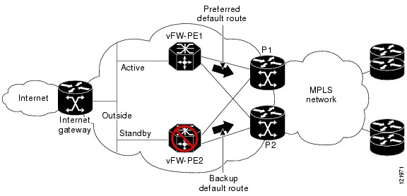
Inter-Chassis Stateful Failover
In this implementation, one FWSM is designated as the active unit, and the other is the standby. The two are connected by a trunk line. All customer VLANs and outside VLANs are trunked across this channel. Figure 5 shows the topology of a network designed for inter-chassis stateful failover.
Figure 5 Inter-Chassis Stateful Failover
Although both the routers are configured to advertise the default route within each VPN, the active unit is preferred. This is achieved by artificially suppressing the default route advertisement from the standby router by the following configuration: the locally generated default static route on the standby router is given a higher administrative distance, and its local preference and weight are reduced when the route is redistributed into BGP.
If the primary router suffers a complete failure, the standby and its FWSM become the active exit point from the VPN to the Internet. If the primary FWSM fails but the primary router remains active, all Internet-bound traffic is still forwarded to the primary router, but the traffic is trunked to the standby FWSM. This setup allows inter-chassis stateful failover of virtual firewall services. For further details, see the " Inter-Chassis Failover" section of this document.
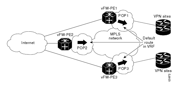
Multiple Exit Point Scenario
SPs whose networks have multiple exit or peering points to the Internet may want to load-balance traffic flows or explicitly configure the exit points from the network. Even when one default route is preferred by a PE, the availability of additional exit points provides redundancy with the VPN network for Internet access. Figure 6 shows the topology of a network designed for multiple exit points.
Figure 6 Multiple-Exit-Point Topology
Depending on the desired result, there are a number of approaches that can be taken:
•
•
•
IPSec Service Failover
Currently, the VPNSM does not support stateful failover, but stateless failover can be achieved using either Hot Standby Router Protocol (HSRP) with Reverse Route Injection (RRI) or multiple peer statements on the clients. HSRP with RRI is used when routers are co-located. Multiple peer statements are used when routers are geographically dispersed. Each of these implementations is briefly discussed below.
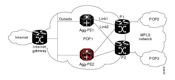
Stateless Failover for Local Routers
Stateless failover is achieved between geographically co-located sites by using HSRP in conjunction with RRI. HSRP provides the mechanism to maintain the active/standby relationship between the routers, and RRI provides the means to dynamically insert and remove routes from the respective VRF routing tables. Because HSRP relies on the need for a broadcast medium to check the status of the active and standby units, this solution can be implemented only between co-located routers. Figure 7 shows the topology of a network designed for stateless failover for local routers.
Figure 7 Stateless Failover for Local Routers
In Figure 7, HSRP is running between the outside interfaces of the routers (Agg-PE1 and Agg-PE2). Depending on the SP deployment, they may have single or dual links to the upstream routers (P1 and P2, in this case). Dual links, the more complex implementation, are discussed below.
Agg-PE1 is given a higher priority (115) than Agg-PE2 (100) so that it will be the active unit. HSRP is also configured to track the two uplinks (Link1 and Link2) on both routers and reduce HSRP priority by 10 in case of individual link failure.
If a single link fails, the HSRP priority of Agg-PE1 is still higher than that of Agg-PE2 (105 versus 100), and Agg-PE1 remains active. If both links fail, Agg-PE2 becomes the active unit because its priority will be higher (100 versus 95).
For IPSec traffic, Agg-PE1 uses RRI to advertise the routes to the active sessions within individual VRFs. If the Agg-PE1 fails, the routes are withdrawn, and all IPSec session are renegotiated with Agg-PE2, which reannounces the routes to IPSec peers using RRI within the VRFs. This dynamically achieves stateless failover using a combination of HSRP and RRI.
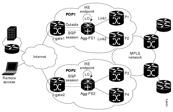
Geographically Dispersed Failover
SPs typically deploy integrated IPSec aggregation and PE devices in different POPs to extend the geographic reach of the service and to guard against POP failures. In such cases, the stateless failover model discussed above using HSRP and RRI cannot be used. Geographically dispersed failover can be achieved by using active and standby IPSec aggregation devices as shown in Figure 8.
Figure 8 Geographically Dispersed Failover
In Figure 8, two PEs (Agg-PE1 and Agg-PE2), which are located in different POPs, accept IPSec sessions. The customers' IPSec VPN remote clients and sites can be configured in such a way that a percentage of them connect to Agg-PE1 as their primary PE (with Agg-PE2 as the backup), and the other clients and sites connect to Agg-PE2 as their primary PE (with Agg-PE1 as the backup). This ensures that all clients can connect to a backup peer if the primary is unreachable, and it also helps load balance between the two PEs.
On the PEs, the IKE termination point is designated as the loopback interface, which is publicly reachable. If the primary PE goes down completely or the outside link goes down, the loopback address becomes unreachable. The clients would then reconnect to the backup peer after DPD times out.
If the core links go down, the loopback interface is still reachable, and IPSec sessions remain active, but the traffic is dropped after decryption. To prevent this from happening, an additional BGP session is established between I-gate1 and Agg-PE1. The only BGP route that this session propagates is the Link1 and Link2 addresses. Additionally, static routes are configured on I-gate1 so that the IKE endpoint (the loopback interface on Agg-PE1) is reachable by Link1 and Link2. (These routes are configured with a higher administrative distance.)
Therefore if Link1 fails, the decrypted traffic is still forwarded by Link2. However, if both links fail, the loopback interface becomes unreachable because the possible next-hop addresses of the static routes are also unreachable. (The Link1 and Link2 addresses are not advertised by the PE in IGP.) The remote client sessions would then time out (based on DPD configuration) and reconnect with their backup peer, thus achieving geographic failover. A similar configuration can be performed on any number of POP locations to achieve redundancy.
Migration of an Existing Cisco 7200 Deployment
SPs who have deployed earlier phases of this solution using the Cisco 7200 series routers have two options for offering Virtual Firewall and IPSec VPN service:
•
•
–
–
–
–
–
QoS Considerations
As described in the previous section, when IPSec is being configured, a unique crypto map is created on each VLAN corresponding to each VPN. This allows for the application of customized QoS policies to the VLAN interfaces. The SP can define customized class maps and policy maps for each customer and apply different service policies for each customer.
The following example applies the service policy "red_qos" to VLAN301 and "blue_qos" to VLAN302. VLAN301 and 302 are the point-to-point VLANs connecting the VPNSM to the MSFC. The red_qos policy limits all outbound encrypted VPN RED traffic to 2 Mbps, and the blue_qos policy limits VPN BLUE traffic to 10 Mbps.
interface Vlan301ip vrf forwarding redip address 192.168.1.1 255.255.255.0crypto map redcrypto engine slot 5service-policy output red_qos!interface Vlan302ip vrf forwarding blueip address 192.168.1.1 255.255.255.0cry map bluecrypto engine slot 5service-policy output blue_qosIf QoS policies need to applied to GRE-encrypted traffic, the service policy must be defined on the physical interface. Packet classification is then performed according to the source and destination addresses of the GRE tunnel endpoint, and policies are applied on a per-tunnel basis.
For more information on QoS options and configurations on the 7600, please refer to the Cisco 7600 Series Router Module Configuration Notes.
Combined Virtual Firewall and IPSec VPN Services
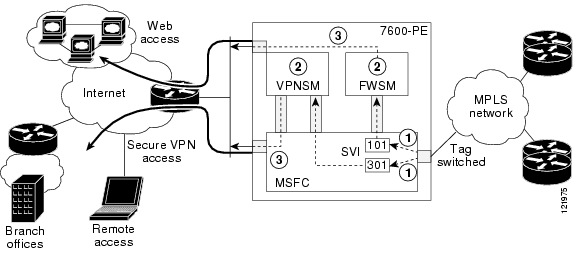
When the combined virtual firewall and IPSec VPN service are offered on a single Cisco 7600 series router, it is important to understand the paths that packets take based on their destinations. Figure 9 shows a scenario in which the FWSM is used for Internet access for MPLS VPN customers, including the remote sites and clients connecting through IPSec. The VPNSM is used to provide secure remote access to the MPLS VPNs.
Figure 9 Combined Virtual FIrewall and IPSec VPN Services
Although the IPSec and virtual firewall services function independently for the most part, the following issues should be considered:
•
•
•
Note
Performance and Scalability
The overall performance and scalability of the network is dependent on a number of factors. The following limits can be used as a basic guideline when designing the solution.
For the Virtual Firewall service:
•
•
•
•
•
For the IPSec service:
•
•
•
•
•
•
Note
Solution Deployment Scenarios
The Cisco Network-Based IPSec VPN Solution is composed of the following three deployment scenarios:
•
•
•
Note
Firewall Services for MPLS VPNs Using the FWSM
This scenario consists of the following three deployment stages:
•
•
Internet Access with External URL Filtering
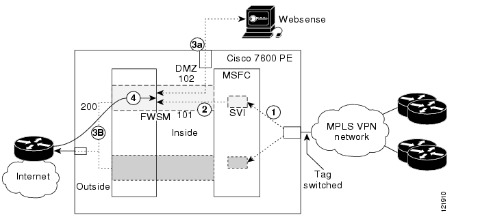
The most common deployment scenario is for a SP to provide Internet access through a virtual firewall for MPLS VPN customers. In conjunction with this service, SPs can also offer external URL filtering. Figure 10 shows the topology for this scenario. The Cisco 7600 PE is expanded to show its interfaces and to illustrate the sequence of events that occur in the operation of the network.
Figure 10 Internet Access with External URL Filtering
The FWSM in the Cisco 7600 PE provides the interface between customer MPLS VPNs and the Internet. RED1 and RED2 are two sites belonging to the VPN customer RED. The PE advertises the default route within each VRF to all other PEs, which in turn propagate the default route to the respective VPN sites. Traffic destined for the Internet is forwarded to the PE within each VRF.
A Switched Virtual Interface (SVI) is configured on the MSFC for each of the VRFs. In this example, VLAN 101 is configured for VPN RED. VLAN 200 is the outside-facing interface for Internet traffic.
Because the customer RED requires external URL filtering, VLAN 102 is configured as a DMZ to the Websense server. All HTTP requests from VPN RED to the Internet are forwarded to the Websense server for URL filtering.
The following sequence of events describes the operation of the network. The numbers correspond to the circled numbers in Figure 10.
1.
2.
3.
4.
The following sections list the necessary configurations to enable this scenario:
Cisco 7600 PE Configuration
The following configuration enables this service on a Cisco 7600 PE router:
firewall multiple-vlan-interfacesfirewall module 4 vlan-group 1firewall vlan-group 1 10,101,102,200ip vrf redrd 125:1route-target export 125:1route-target import 125:1!mpls label protocol ldp!interface Loopback0ip address 10.125.125.1 255.255.255.255!interface GE-WAN2/1description To MPLS Coreip address 10.1.10.1 255.255.255.0negotiation autotag-switching ipmls qos trust dscp!interface FastEthernet3/1no ip addressswitchportswitchport access vlan 200switchport mode access!interface FastEthernet3/2no ip addressswitchportswitchport trunk encapsulation dot1qswitchport trunk allowed vlan 102switchport mode trunk!interface Vlan101ip vrf forwarding redip address 10.1.1.1 255.255.255.0!interface Vlan200ip address 172.26.185.33 255.255.255.0!router ospf 1log-adjacency-changesredistribute connected subnetsnetwork 10.1.10.0 0.0.0.255 area 0network 10.125.125.1 0.0.0.0 area 0!router bgp 10no synchronizationbgp log-neighbor-changesneighbor 10.125.125.7 remote-as 125neighbor 10.125.125.7 update-source Loopback0no auto-summary!address-family vpnv4neighbor 10.125.125.7 activateneighbor 10.125.125.7 send-community bothexit-address-family!address-family ipv4 vrf redredistribute connectedredistribute staticdefault-information originateno auto-summaryno synchronizationexit-address-family!ip classlessip route 0.0.0.0 0.0.0.0 172.26.185.1ip route vrf red 0.0.0.0 0.0.0.0 10.1.1.2FWSM System Configuration
The following system configuration on the FWSM enables this service:
class goldlimit-resource Xlates 10000limit-resource Telnet 5limit-resource All 0!admin-context admincontext adminallocate-interface vlan10config-url disk:/admin.cfg!context redmember goldallocate-interface vlan101-102allocate-interface vlan200config-url disk:/red.cfgFWSM Context Configuration
The following context configuration on the FWSM enables this service:
nameif vlan200 outside security0nameif vlan101 redin security100nameif vlan102 dmz security50hostname redaccess-list 101 extended permit ip any anyaccess-list 102 extended permit tcp host 192.168.1.2 any eq httpicmp permit 10.1.0.0 255.255.0.0 redinip address outside 172.26.185.66 255.255.255.0ip address redin 10.1.1.2 255.255.255.0ip address dmz 192.168.1.1 255.255.255.0url-server (dmz) vendor websense host 192.168.1.2url-cache dst 128filter url http 10.1.0.0 255.255.0.0 0 0global (outside) 103 interfacenat (redin) 103 10.1.0.0 255.255.0.0static (dmz,outside) 172.26.185.33 192.168.1.2 netmask 255.255.255.255access-group 101 in interface redinaccess-group 102 in interface dmz!route outside 0.0.0.0 0.0.0.0 172.26.185.1 1route redin 10.1.100.0 255.255.255.0 10.1.1.1 1route redin 10.1.20.0 255.255.255.0 10.1.1.1 1route redin 0.0.0.0 0.0.0.0 10.1.1.1 10Site-to-Site Virtual Firewall Service
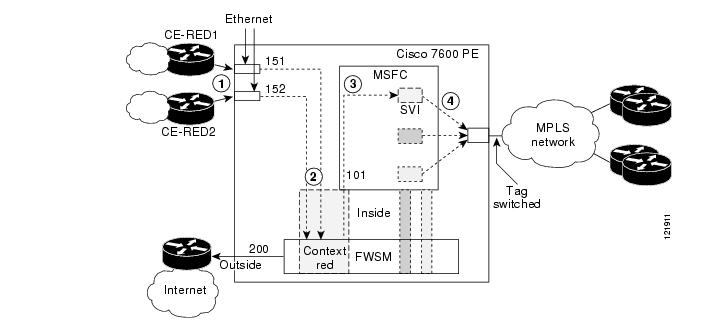
After SPs have deployed Internet Access with External URL Filtering, they may wish to expand their offering to include site-to-site virtual firewalls. In addition to providing virtual firewall services between customer networks and the Internet, the FWSM provides firewall service between locally connected sites and all remote sites by using MPLS VPNs.
Figure 11 shows the topology for this scenario. The Cisco 7600 PE is expanded to show its interfaces and to illustrate the sequence of events that occur in the operation of the network.
Figure 11 Site-to-Site Virtual Firewall Service
VLAN 200 is the outside-facing interface for Internet traffic for all of the RED VPN sites. MPLS VPN traffic belonging to the RED VPN is forwarded by way of VLAN 101. CE-RED1 and CE-RED2 are locally connected CEs. CE-RED connects to the PE by way of VLAN interface 151, and CE-RED2 connects to the PE by way of VLAN interface 152.
Note
The following sequence of event describes the operation of the network. The numbers correspond to the circled numbers in Figure 11.
1.
2.
3.
4.
The following sections list the necessary configurations to enable this scenario:
•
Cisco 7600 Router Configuration
The following configuration enables this service on a Cisco 7600 PE router.
Note
firewall multiple-vlan-interfacesfirewall module 4 vlan-group 1firewall vlan-group 1 10,101,151,152,200ip vrf redrd 125:1route-target export 125:1route-target import 125:1!mpls label protocol ldp!interface Loopback0ip address 10.125.125.1 255.255.255.255!interface GE-WAN2/1description To MPLS Coreip address 10.1.10.1 255.255.255.0negotiation autotag-switching ipmls qos trust dscp!interface FastEthernet3/1no ip addressswitchportswitchport access vlan 200switchport mode access!interface FastEthernet3/2no ip addressswitchportswitchport trunk encapsulation dot1qswitchport trunk allowed vlan 151switchport mode trunk!interface FastEthernet3/3no ip addressswitchportswitchport trunk encapsulation dot1qswitchport trunk allowed vlan 152switchport mode trunk!interface Vlan101ip vrf forwarding redip address 101.1.1 255.255.255.0!interface Vlan200ip address 172.26.185.33 255.255.255.0!router ospf 1log-adjacency-changesredistribute connected subnetsnetwork 10.1.10.0 0.0.0.255 area 0network 10.125.125.1 0.0.0.0 area 0!router bgp 10no synchronizationbgp log-neighbor-changesneighbor 10.125.125.7 remote-as 10neighbor 10.125.125.7 update-source Loopback0no auto-summary!address-family vpnv4neighbor 10.125.125.7 activateneighbor 10.125.125.7 send-community bothexit-address-family!address-family ipv4 vrf redredistribute connectedredistribute staticdefault-information originateno auto-summaryno synchronizationexit-address-family!ip classlessip route 0.0.0.0 0.0.0.0 172.26.185.1ip route vrf red 0.0.0.0 0.0.0.0 10.1.1.2FWSM System Configuration
The following system configuration on the FWSM enables this service.
class goldlimit-resource Xlates 10000limit-resource Telnet 5limit-resource All 0!admin-context admincontext adminallocate-interface vlan10config-url disk:/admin.cfg!context redmember goldallocate-interface vlan101allocate-interface vlan151-152allocate-interface vlan200config-url disk:/red.cfgFWSM Context Configuration
The following context configuration on the FWSM enables this service.
nameif vlan200 outside security0nameif vlan101 redin security100nameif vlan151 ce1 security100nameif vlan152 ce2 security100hostname redsame-security-traffic permit inter-interfaceaccess-list 101 extended permit icmp any anyaccess-list 102 extended permit icmp any anyaccess-list 102 extended permit tcp 10.1.0.0 255.255.0.0 host 10.1.1.2 eq telnetaccess-list 102 extended permit udp 10.1.100.0 255.255.255.0 host 10.1.1.2 eq radiusicmp permit 10.1.0.0 255.255.0.0 redinicmp permit 10.1.0.0 255.255.0.0 ce1icmp permit 10.1.0.0 255.255.0.0 ce2ip address outside 172.26.185.66 255.255.255.0ip address redin 10.1.1.2 255.255.255.0ip address ce1 10.1.21.2 255.255.255.0ip address ce2 10.1.22.2 255.255.255.0global (outside) 103 interfacenat (redin) 103 10.1.20.0 255.255.255.0nat (ce1) 103 10.1.21.0 255.255.255.0nat (ce2) 103 10.1.22.0 255.255.255.0access-group 102 in interface redinaccess-group 101 in interface ce1access-group 101 in interface ce2!route outside 0.0.0.0 0.0.0.0 172.26.185.1 1route redin 10.1.100.0 255.255.255.0 10.1.1.1 1route redin 10.1.20.0 255.255.255.0 10.1.1.1 1route redin 0.0.0.0 0.0.0.0 10.1.1.1 10route ce1 101.1.1.0 255.255.255.0 10.1.21.1 1add route ce2 102.1.1.0 255.255.255.0 10.1.22.1Inter-Chassis Failover
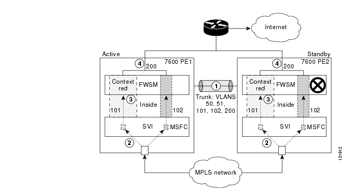
Inter-chassis failover provides greatly increased network reliability by adding a backup PE. Two Cisco 7600s (7600-PE1 and 7600-PE2) are deployed, each having its own FWSM. Both PEs are connected to the MPLS network using Gigabit Ethernet interfaces. The FWSM in PE1 is designated as active, and the FWSM in PE2 is designated as standby.
Figure 12 is a block diagram with the primary and secondary Cisco 7600 PEs expanded to show their interfaces and to illustrate the sequence of events that occur in the operation of the network.
Figure 12 Inter-Chassis Failover
An SVI, defined as VLAN 101 for VPN RED, is used to forward traffic to the inside interface of the firewall context RED. VLAN 200 is defined as the outside VLAN for Internet access.
VLANs 50 and 51 are used as the failover and state links, respectively. All of the VLANs (50, 51, 101, 200, and any other customer VLAN) are trunked between the two PEs to achieve redundancy.
PE1 and PE2 advertise default routes within the VPN RED, but PE1 is the preferred exit point for all the sites in VPN RED. PE2 advertises its default route only if the default route from PE1 goes down. This is achieved by changing the BGP attributes of the default route as follows:
•
•
•
The following sequence of event describes the operation of the network. The numbers correspond to the circled numbers in Figure 12.
1.
2.
3.
4.
As discussed in the " Virtual Firewall Service Failover" portion of the " Design Considerations" section of this document, in case of a complete router failure, 7600-PE2 advertises its default route, and all Internet-bound traffic within each of the VRFs is forwarded to it.
The following sections list the necessary configurations to enable this scenario:
•
•
•
•
•
Primary Cisco 7600 Router Configuration
The following configuration enables the inter-chassis service on the primary Cisco 7600 PE router.
hostname 7600-PE1!firewall multiple-vlan-interfacesfirewall module 4 vlan-group 1firewall vlan-group 1 10,101,200!ip vrf redrd 125:1route-target export 125:1route-target import 125:1!mpls label protocol ldp!interface Loopback0ip address 10.125.125.1 255.255.255.255!interface range gigabitethernet 1/1-3channel-group 1 mode onswitchport trunk encapsulation dot1q!interface GE-WAN2/1description To MPLS Coreip address 10.1.10.1 255.255.255.0negotiation autotag-switching ipmls qos trust dscp!interface FastEthernet3/1no ip addressswitchportswitchport access vlan 200switchport mode access!interface Vlan101ip vrf forwarding redip address 10.1.1.1 255.255.255.0!interface Vlan200ip address 172.26.185.33 255.255.255.0!router ospf 1log-adjacency-changesredistribute connected subnetsnetwork 10.1.10.0 0.0.0.255 area 0network 10.125.125.1 0.0.0.0 area 0!router bgp 10no synchronizationbgp log-neighbor-changesneighbor 10.125.125.7 remote-as 10neighbor 10.125.125.7 update-source Loopback0no auto-summary!address-family vpnv4neighbor 10.125.125.7 activateneighbor 10.125.125.7 send-community bothexit-address-family!address-family ipv4 vrf redredistribute connectedredistribute static route-map set-lpdefault-information originateno auto-summaryno synchronizationexit-address-family!ip route 0.0.0.0 0.0.0.0 172.26.185.1ip route vrf red 0.0.0.0 0.0.0.0 10.1.1.2!route-map set-lp permit 1set local-preference 120Secondary Cisco 7600 Router Configuration
The following configuration enables the inter-chassis service on the secondary Cisco 7600 PE router.
Note
hostname 7600-PE2router bgp 10address-family ipv4 vrf redredistribute connectedredistribute static route-map testdefault-information originateno auto-summaryno synchronizationexit-address-family!ip route vrf red 0.0.0.0 0.0.0.0 10.1.20.1 210!route-map test permit 1set local-preference 100set weight 0Primary FWSM System Configuration
The following configuration enables the inter-chassis service on the primary FWSM system configuration.
class goldlimit-resource Xlates 10000limit-resource Telnet 5limit-resource All 0!failover lan interface fail vlan 50failover link state vlan 51failover lan unit primaryfailover interface ip fail 192.168.1.1 255.255.255.0 standby 192.168.1.2failover interface ip state 192.168.2.1 255.255.255.0 standby 192.168.2.2failover interface-policy 50%failover replication httpfailover!admin-context admincontext adminallocate-interface vlan10config-url disk:/admin.cfg!context redmember goldallocate-interface vlan101allocate-interface vlan200config-url disk:/red.cfgPrimary FWSM Context Configuration
The following configuration enables the inter-chassis service on the primary FWSM context configuration.
nameif vlan200 outside security0nameif vlan101 redin security100hostname redaccess-list 101 extended permit ip any anyicmp permit 10.1.0.0 255.255.0.0 redinip address outside 172.26.185.66 255.255.255.0ip address redin 10.1.1.2 255.255.255.0global (outside) 103 interfacenat (redin) 103 10.1.0.0 255.255.0.0access-group 101 in interface redin!route outside 0.0.0.0 0.0.0.0 172.26.185.1 1route redin 10.1.100.0 255.255.255.0 10.1.1.1 1route redin 10.1.20.0 255.255.255.0 10.1.1.1 1route redin 0.0.0.0 0.0.0.0 10.1.1.1 10Secondary FWSM System Configuration
The following configuration enables the inter-chassis service on the secondary FWSM system configuration.
Note
failover lan interface fail vlan 50failover interface ip fail 192.168.1.1 255.255.255.250 standby 192.168.1.2failover lan unit secondaryfailoverIPSec Aggregation Using the VPNSM
This scenario describes how to integrate IPSec into an existing MPLS VPN using the VPNSM module on the Cisco 7600. The service supports both site-to-site VPNs (using either native or GRE) and remote access clients (using either PCs or Easy VPN). Figure 12 shows a block diagram of the Cisco 7600 PE configured for IPSec aggregation using the VPNSM:
Figure 13 IPSec Aggregation using the VPNSM
The VPNSM has one inside interface (Gigabit Ethernet 5/1) and one outside interface (Gigabit Ethernet 5/2) that are used to carry encrypted and decrypted traffic in and out of the VPNSM. In this example, a Switched Virtual Interface (SVI - VLAN301) is defined on the MSFC. Configuring the crypto engine command for this VLAN causes the VLAN to become a special point-to-point VLAN between the MSFC and the VPNSM.
The following sequence of events describes the outbound packet flow. The numbers correspond to the circled numbers in Figure 13.
1.
2.
3.
4.
The following sequence of events describes the inbound packet flow. The numbers correspond to the circled numbers in Figure 13.
1.
2.
3.
4.
Cisco 7600 PE Configuration
The following configuration enables IPSec aggregation for VPN RED on the MSFC of the Cisco 7600. No configuration is required on the VPNSM.
Note
ip vrf redrd 125:1route-target export 125:1route-target import 125:1!crypto keyring redpre-shared-key address 172.26.185.42 key red789pre-shared-key address 172.26.185.43 key red789!crypto isakmp policy 1encr 3desauthentication pre-sharegroup 2!crypto isakmp policy 2encr 3desauthentication pre-share!crypto isakmp client configuration group red-rakey red789pool red-poolsave-passwordcrypto isakmp profile red-ravrf redmatch identity group red-raclient authentication list localistisakmp authorization list localistclient configuration address respondcrypto isakmp profile red-sitevrf redkeyring redmatch identity address 172.26.185.43 255.255.255.255crypto isakmp profile red-grekeyring redmatch identity address 172.26.185.42 255.255.255.255!crypto IPSec transform-set tset1 esp-3des esp-sha-hmaccrypto IPSec transform-set tset2 esp-3des esp-sha-hmacmode transport!crypto IPSec profile red-greset transform-set tset2set isakmp-profile red-gre!crypto dynamic-map red-dyna 1set transform-set tset1set isakmp-profile red-rareverse-route!crypto map red local-address FastEthernet3/4crypto map red 1 IPSec-isakmpset peer 172.26.185.43set transform-set tset1set isakmp-profile red-sitematch address 101reverse-routecrypto map red 1000 IPSec-isakmp dynamic red-dyna!crypto engine mode vrf!interface Loopback0ip address 10.125.125.1 255.255.255.255!interface Tunnel1ip vrf forwarding redip address 10.168.1.1 255.255.255.252tunnel source FastEthernet3/4tunnel destination 172.26.185.42tunnel protection IPSec profile red-grecrypto engine slot 5!interface GE-WAN2/1description To MPLS Coreip address 10.1.10.1 255.255.255.0negotiation autotag-switching ipmls qos trust dscp!interface FastEthernet3/4ip address 172.26.185.33 255.255.255.0crypto engine slot 5!interface GigabitEthernet5/1no ip addressflowcontrol receive onflowcontrol send offswitchportswitchport trunk encapsulation dot1qswitchport trunk allowed vlan 1,301,1002-1005switchport mode trunkspanning-tree portfast trunk!interface GigabitEthernet5/2no ip addressflowcontrol receive onflowcontrol send offswitchportswitchport trunk encapsulation dot1qswitchport trunk allowed vlan 1,1002-1005switchport mode trunkspanning-tree portfast trunk!interface Vlan301ip vrf forwarding redip address 192.168.1.1 255.255.255.0crypto map redcrypto engine slot 5!router ospf 1log-adjacency-changesredistribute connected subnetsnetwork 10.1.10.0 0.0.0.255 area 0network 10.125.125.1 0.0.0.0 area 0!router ripversion 2!address-family ipv4 vrf redredistribute static metric 5redistribute bgp 10 metric 5network 10.168.0.0no auto-summaryexit-address-family!router bgp 10no synchronizationbgp log-neighbor-changesneighbor 10.125.125.7 remote-as 10neighbor 10.125.125.7 update-source Loopback0no auto-summary!address-family vpnv4neighbor 10.125.125.7 activateneighbor 10.125.125.7 send-community bothexit-address-family!address-family ipv4 vrf redredistribute connectedredistribute staticredistribute ripno auto-summaryno synchronizationexit-address-family!ip local pool red-pool 172.30.1.1 172.30.1.10 group redip route 0.0.0.0 0.0.0.0 172.26.185.1Combined IPSec Aggregation and Firewall Service
Note
Verifying the Cisco Network-Based Security Services Solution
This section describes how to verify that the Cisco network-based security services solution is functioning properly. It contains the following sections:
•
Verifying the FWSM
This section describes how to verify that the FWSM is functioning properly. It contains the following sections:
•
•
•
•
Verifying the FWSM from the MSFC
To check the status of the FWSM, including the versions of the hardware and software, use the show module module command:
router# show module 4Mod Ports Card Type Model Serial No.--- ----- -------------------------------------- ------------------ -----------4 6 Firewall Module WS-SVC-FWM-1 SAD074604TFMod MAC addresses Hw Fw Sw Status--- ---------------------------------- ------ ------------ ------------ -------4 0003.fead.3292 to 0003.fead.3299 2.0 7.2(1) 2.2(1) OkMod Online Diag Status--- -------------------4 PassTo check the VLANs assigned to the FWSM, use the show firewall vlan-group command:
router# show firewall vlan-groupGroup vlans----- ------1 10-11,101-102,151-152,200To verify MPLS VPNs and IP routing and forwarding functionality, use standard MPLS, IP, and CEF commands.
Verifying the FWSM from the FWSM System Space
From the FWSM system space, to verify the contexts configured, VLANs, and resource limiting class assigned to each context, use the show context command:
router# show contextContext Name Class Interfaces URL*admin gold vlan10-11 disk:/admin.cfgred gold vlan101,151-152,200 disk:/red.cfgTo verity resource limiting classes, allocations and usage, use the following commands:
router# show classClass Name Members ID Flagsdefault All 1 0001gold 2 2 0000router# show resource allocateResource Total % of AvailConns [rate] unlimitedFixups [rate] unlimitedSyslogs [rate] unlimitedConns unlimitedHosts unlimitedIPSec 10 100.00%Mac-addresses 131070 200.00%SSH 10 10.00%Telnet 10 10.00%Xlates 20000 7.62%router# show resources usageResource Current Peak Limit Denied ContextTelnet 1 1 5 0 systemTo view CPU utilization and memory usage, use the show cpu and show memory commands respectively.
router# show cpuCPU utilization for 5 seconds = 6%; 1 minute: 2%; 5 minutes: 1%router# show memoryFree memory: 796820220 bytes (74%)Used memory: 276921604 bytes (26%)------------- ----------------Total memory: 1073741824 bytes (100%)To check the failover status, use the show failover command. If interface monitoring is enabled, the status of the monitored interface can be viewed using the show monitor-interface command.
Verifying the FWSM from Within the FWSM Context Space
To verify the status of individual VLANs assigned to a context, use the show interface command:
router# show interfaceInterface vlan101 "redin", is up, line protocol is upMAC address 000d.edee.a900, MTU 1500IP address 10.1.1.2, subnet mask 255.255.255.0Received 84 packets, 6212 bytesTransmitted 75 packets, 154950 bytesDropped 534359 packetsInterface vlan151 "ce2", is up, line protocol is upMAC address 000d.edee.a900, MTU 1500IP address 10.1.21.2, subnet mask 255.255.255.0Received 81 packets, 5858 bytesTransmitted 75 packets, 154950 bytesDropped 532590 packetsInterface vlan152 "ce3", is up, line protocol is upMAC address 000d.edee.a900, MTU 1500IP address 10.1.22.2, subnet mask 255.255.255.0Received 0 packets, 0 bytesTransmitted 0 packets, 0 bytesDropped 532589 packetsInterface vlan200 "outside", is up, line protocol is upMAC address 000d.edee.a900, MTU 1500IP address 172.26.185.66, subnet mask 255.255.255.0Received 257058 packets, 79656189 bytesTransmitted 176 packets, 363616 bytesDropped 790364 packetsTo view the number of authenticated users, use the show uauth command:
router# show uauthCurrent Most SeenAuthenticated Users 0 0Authen In Progress 0 0To verify that the NAT is functioning as desired, use the show xlate command:
router# show xlate5 in use, 10 most usedPAT Global 172.26.185.66(1039) Local 10.1.20.1 ICMP id 5650PAT Global 172.26.185.66(1040) Local 10.1.20.1 ICMP id 5651PAT Global 172.26.185.66(1041) Local 10.1.20.1 ICMP id 5652PAT Global 172.26.185.66(1042) Local 10.1.20.1 ICMP id 5653PAT Global 172.26.185.66(1043) Local 10.1.20.1 ICMP id 5654To view H.323 related fixup information uses the following show commands:
•
•
•
When an external URL-filtering server is used, the following commands can be used to view information on this service:
•
•
•
Verifying the IPSec VPN Service
This section describes how to verify that the IPSec VPN services are functioning properly. It contains the following sections:
•
•
Verifying the Status of the VPNSM
To verify that the crypto engine is enabled and active, use the show crypto engine configuration command:
router# show crypto engine configurationcrypto engine name: Virtual Private Network (VPN) Modulecrypto engine type: hardwareCompression: NoDES: Yes3 DES: YesAES CBC: NoAES CNTR: NoMaximum buffer length: 1488Maximum DH index: 9999Maximum SA index: 10921Maximum Flow index: 21842Maximum RSA key size: 1024crypto engine in slot: 5platform: VPN hardware acceleratorCrypto Adjacency Counts:Lock Count: 0Unlock Count: 0crypto lib version: 17.0.0IPSec lib version: 2.0.0To verify the VLAN connections in and out of the crypto engine, use the show crypto vlan command:
router# show crypto vlanInterface VLAN 301 on IPSec Service Module port 5/1 connected to VLAN 1022 with crypto map set redInterface VLAN 302 on IPSec Service Module port 5/1 connected to VLAN 1022Interface VLAN 1024 on IPSec Service Module port 5/1 connected to VLAN 1022Tunnel1 is accelerated via IPSec SM in slot 5To view encryption layer statistics, use the show crypto eli command:
router# show crypto eliHardware Encryption Layer : ACTIVENumber of crypto engines = 1 .CryptoEngine-4 (slot-5) details.Capability-IPSec : No-IPPCP, 3DES, NoAES, RSAIKE-Session : 2 active, 10921 max, 0 failedDH-Key : 0 active, 9999 max, 0 failedIPSec-Session : 4 active, 21842 max, 0 failedVerifying the IPSec Connection
To view more details on individual IPSec security associations (SA), such as packets encrypted and decrypted, errors, proxies negotiated, use the show crypto IPSec sa command.
router# show crypto IPSec sainterface: Tunnel1Crypto map tag: Tunnel1-head-0, local addr. 172.26.185.33protected vrf:local ident (addr/mask/prot/port): (172.26.185.33/255.255.255.255/47/0)remote ident (addr/mask/prot/port): (172.26.185.42/255.255.255.255/47/0)current_peer: 172.26.185.42:500PERMIT, flags={origin_is_acl,}#pkts encaps: 24865, #pkts encrypt: 24865, #pkts digest: 24865#pkts decaps: 24821, #pkts decrypt: 24821, #pkts verify: 24821#pkts compressed: 0, #pkts decompressed: 0#pkts not compressed: 0, #pkts compr. failed: 0#pkts not decompressed: 0, #pkts decompress failed: 0#send errors 1, #recv errors 0local crypto endpt.: 172.26.185.33, remote crypto endpt.: 172.26.185.42path mtu 1500, media mtu 1500current outbound spi: 4A3C2FBBinbound esp sas:spi: 0xA4B2C28C(2763178636)transform: esp-3des esp-sha-hmac ,in use settings ={Tunnel, }slot: 5, conn id: 10925, flow_id: 3, crypto map: Tunnel1-head-0crypto engine type: Hardware, engine_id: 2sa timing: remaining key lifetime (k/sec): (4607995/3180)ike_cookies: 28BF5A39 ECFEB5A9 7B8CF22F 269632BDIV size: 8 bytesreplay detection support: Yinbound ah sas:inbound pcp sas:outbound esp sas:spi: 0x4A3C2FBB(1245458363)transform: esp-3des esp-sha-hmac ,in use settings ={Tunnel, }slot: 5, conn id: 10926, flow_id: 4, crypto map: Tunnel1-head-0crypto engine type: Hardware, engine_id: 2sa timing: remaining key lifetime (k/sec): (4607994/3179)ike_cookies: 28BF5A39 ECFEB5A9 7B8CF22F 269632BDIV size: 8 bytesreplay detection support: Youtbound ah sas:outbound pcp sas:
Note
Verifying Routing and Forwarding
To verify that a route was correctly installed in the VRF table, use the show ip route vrf vrf ip command. In this output, ensure that the route is pointing out of the correct interface (Tunnel1, in this case).
router# show ip route vrf red 10.64.2.1Routing entry for 10.64.2.0/24Known via "rip", distance 120, metric 1Redistributing via bgp 10, ripAdvertised by bgp 10Last update from 10.168.1.2 on Tunnel1, 00:00:18 agoRouting Descriptor Blocks:* 10.168.1.2, from 10.1681.1.2, 00:00:18 ago, via Tunnel1Route metric is 1, traffic share count is 1To verify that the MPLS forwarding table for locally learned routes is set up correctly, use the show mpls forwarding vrf vrf ip command:
router# show mpls for vrf red 10.64.2.1Local Outgoing Prefix Bytes tag Outgoing Next Hoptag tag or VC or Tunnel Id switched interface31 Untagged 10.64.2.0/24[V] 3000 Tu1 point2pointTo verify that the MPLS and VPN labels are correctly learned for a remote route, use the show ip cef vrf vrf ip command:
router# show ip cef vrf red 10.1.20.010.1.20.0/24, version 19, epoch 0, cached adjacency 10.1.10.20 packets, 0 bytestag information set, all rewrites ownedlocal tag: VPN-route-headfast tag rewrite with GE2/1, 10.1.10.2, tags imposed: {24 35}via 10.125.125.4, 0 dependencies, recursivenext hop 10.1.10.2, GE-WAN2/1 via 10.125.125.4/32 (Default)valid cached adjacencytag rewrite with GE2/1, 10.1.10.2, tags imposed: {24 35}In this output, labels (24, 35) will be imposed while packets are being sent to 10.1.20.0/24. The VPN label (35) can be verified on the remote advertising PE while the outer MPLS label (24) advertisement can be verified on a hop-by-hop basis toward the remote PE.
Debugging IPSec
Use the following commands to debug IKE and IPSec:
•
•
If there are a large number of sessions connected or connecting, use conditional debug, which can be enabled with a number of parameters.
router# debug cry cond ?connid IKE/IPSec connection-id filterflowid IPSec flow-id filterfvrf Front-door VRF filterivrf Inside VRF filterpeer IKE peer filterreset Delete all debug filters and turn off conditional debugspi SPI (Security Policy Index) filterunmatched Output debugs even if no context availableRelated Documents
The following MPLS VPN RFCs are relevant to this solution:
•
•
•
The following IPSec RFCs are relevant to this solution:
•
•
•
•
•
Table 2 lists related documents.
CCSP, the Cisco Square Bridge logo, Cisco Unity, Follow Me Browsing, FormShare, and StackWise are trademarks of Cisco Systems, Inc.; Changing the Way We Work, Live, Play, and Learn, and iQuick Study are service marks of Cisco Systems, Inc.; and Aironet, ASIST, BPX, Catalyst, CCDA, CCDP, CCIE, CCIP, CCNA, CCNP, Cisco, the Cisco Certified Internetwork Expert logo, Cisco IOS, Cisco Press, Cisco Systems, Cisco Systems Capital, the Cisco Systems logo, Empowering the Internet Generation, Enterprise/Solver, EtherChannel, EtherFast, EtherSwitch, Fast Step, GigaDrive, GigaStack, HomeLink, Internet Quotient, IOS, IP/TV, iQ Expertise, the iQ logo, iQ Net Readiness Scorecard, LightStream, Linksys, MeetingPlace, MGX, the Networkers logo, Networking Academy, Network Registrar, Packet, PIX, Post-Routing, Pre-Routing, ProConnect, RateMUX, Registrar, ScriptShare, SlideCast, SMARTnet, StrataView Plus, SwitchProbe, TeleRouter, The Fastest Way to Increase Your Internet Quotient, TransPath, and VCO are registered trademarks of Cisco Systems, Inc. and/or its affiliates in the United States and certain other countries.
All other trademarks mentioned in this document or Website are the property of their respective owners. The use of the word partner does not imply a partnership relationship between Cisco and any other company. (0406R)
Copyright © 2004, Cisco Systems, Inc.
All rights reserved.
![]()
![]()
![]()
![]()
![]()
![]()
![]()
![]()
Posted: Wed Nov 10 20:58:05 PST 2004
All contents are Copyright © 1992--2004 Cisco Systems, Inc. All rights reserved.
Important Notices and Privacy Statement.