|
|

Table Of Contents
Cisco Unified Communications 500 Series
Cisco One-Year Limited Hardware Warranty Terms
Cisco Product Identification Tool
Install Cisco Unified 500 Series Chassis and Power Supply
Wall-Mounting the Cisco Unified 500 Series (8- and 16-user models only)
Rack-Mount the Cisco Unified 500 Series
Create Initial Software Configuration
Install a Cisco Catalyst Express 520 for a Cisco Unified 500 Series
Connect Switch to a Cisco Unified 500 Series
Connect Interfaces and Devices
Modify the Software Configuration
Information About the Software Configuration
Default Software Configuration
Configure Localization Support
Install Cisco Configuration Assistant
Log Into Cisco Unified CME and Cisco Unity Express GUI
Log Into Cisco Unified CME Phone User Page
Obtaining Documentation, Obtaining Support, and Security Guidelines
Getting Started Guide
Cisco Unified Communications 500 Series
INCLUDING LICENSE AND WARRANTY1 Cisco One-Year Limited Hardware Warranty Terms
There are special terms applicable to your hardware warranty and various services that you can use during the warranty period. Your formal Warranty Statement, including the warranties and license agreements applicable to Cisco software, is available on Cisco.com. Follow these steps to access and download your warranty and license agreements from Cisco.com.
1.
Launch your browser, and go to this URL:
http://www.cisco.com/univercd/cc/td/doc/es_inpck/cetrans.htm
The Warranties and License Agreements page appears.
2.
a.
b.
c.
The Cisco Limited Warranty and Software License page from the Information Packet appears.
d.
Note
3.
a.
78-10747-01C0
b.
c.
The Cisco warranty page appears.
d.
Note
You can also contact the Cisco service and support website for assistance:
http://www.cisco.com/en/US/support/index.html
Duration of Hardware Warranty
One (1) Year
Replacement, Repair, or Refund Policy for Hardware
Cisco or its service center will use commercially reasonable efforts to ship a replacement part within ten (10) working days after receipt of a Return Materials Authorization (RMA) request. Actual delivery times can vary, depending on the customer location.
Cisco reserves the right to refund the purchase price as its exclusive warranty remedy.
To Receive a Return Materials Authorization (RMA) Number
Contact the company from whom you purchased the product. If you purchased the product directly from Cisco, contact your Cisco Sales and Service Representative.
Complete the information below, and keep it for reference.
Company product purchased from
Company telephone number
Product model number
Product serial number
Maintenance contract number
2 Overview
This section provides overview and detailed information about the Cisco Unified Communications 500 Series for Small Business (Cisco Unified 500 Series).
The Cisco Unified 500 Series product family is an all-in-one, simple, smart, and affordable unified communications solution designed specifically for growing businesses with 8 to 50 employees. Each configuration of Cisco Unified 500 Series is tied to a maximum number of supported users and includes relevant licenses for call control, voice messaging, and Cisco Unified IP Phones.
The Cisco Unified 500 Series family consists of the following two platforms:
•
•
The 8- and 16-user platform includes 8 switched Power-over-Ethernet (PoE) ports, 4 foreign exchange stations (FXS) ports, 4 foreign exchange office (FXO) or 2 ISDN BRI ports for international deployments, voice messaging, automated attendant, a music-on-hold (MoH) audio port, a WAN Ethernet uplink port, an Ethernet expansion port, and a console/aux port.
The 32-user platform includes 8 switched Power-over-Ethernet (PoE) ports, 4 foreign exchange stations (FXS) ports, 8 foreign exchange office (FXO) or 4 ISDN BRI ports.
The 48-user platform includes 8 switched Power-over-Ethernet (PoE) ports, 4 foreign exchange stations (FXS) ports, 12 foreign exchange office (FXO) or 6 ISDN BRI ports. Alternatively, the 48-user platform could include 8 switched Power-over-Ethernet (PoE) ports, 4 foreign exchange stations (FXS) ports, 4 foreign exchange office (FXO) or 2 ISDN BRI ports and one T1/E1 voice controller.
To physically expand the base configuration of 8 PoE ports to a larger number of user densities, the solution supports a Cisco Unified Communications companion switch. The specialized companion switch is part of the Cisco Catalyst Express family and supports simplified and immediately operational deployments.
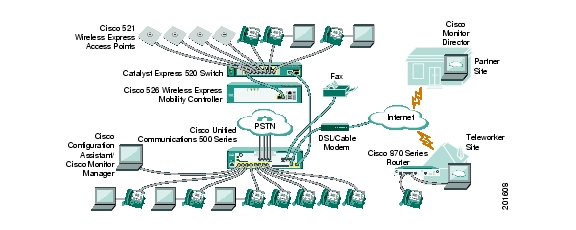
Figure 1 shows the typical deployment of a Cisco Unified 500 Series in a Cisco Smart Business Communications System. The Cisco Smart Business Communications System is a unified communications solution for small businesses that provides voice, data, video, security, and wireless capabilities while integrating with existing desktop applications like calendar, e-mail, and Customer Relationship Management (CRM).
Figure 1 Cisco Unified 500 Series: Typical Deployment
Hardware Configuration
Table 1 summarizes the maximum configurations possible, based on built-in ports and other hardware features of the Cisco Unified 500 Series, and organized by model.
.
Table 2 lists the labels and descriptions for the WAN, LAN, and other interfaces, along with the values for these interfaces in the preconfigured software configuration on the Cisco Unified 500 Series.
Note
* Only one optional VIC can be factory-installed in a Cisco Unified 500 Series.
Table 3 lists the labels and descriptions for the interfaces on a Cisco Catalyst Express 520, along with the values for these interfaces in the software configuration on the Cisco Unified 500 Series:
Table 3 Cisco Catalyst Express 520 Switch: Interfaces
Ethernet 10/100/1000 dual purpose port
1000BASE-X
GigabitEthernet1
Small form-factor pluggable (SFP) module slot for uplink or server connectivity.
1000BASE-FX
Fast Ethernet 10/100 Power over Ethernet (PoE) ports
Left-to-right,
10BASE-T / 100BASE-TX and 1X-8X or 1X-24XLeft-to-right,
FastEthernet1 to 8
FastEthernet1 to 24
Table 4 lists the default values for IP addresses in the preconfigured software configuration for a Cisco Unified 500 Series system
.
Table 4 IP Addresses and Subnet Mask
Cisco Unified Communications Manager Express (Cisco Unified CME)
10.1.1.1
255.255.255.0All IP phones to be connected
10.1.1.11 to 10.1.1.254
255.255.255.0All data devices to be connected
192.168.10.11 to 192.168.10.254
255.255.255.0Network on expansion port of Cisco Unified 500 Series
192.168.10.1
255.255.255.0
Software Components
The Cisco Unified 500 Series is shipped with a factory-installed software configuration for a basic IP telephony system. This system enables phone users to make and receive calls using the preconfigured numbers on their IP phones within minutes after connecting the Cisco Unified 500 Series to the Ethernet and their IP phones to the platform. For informations, see the "Default Software Configuration" section.
Table 5 summarizes the software components of the Cisco Unified 500 Series.
Table 5 Cisco Unified 500 Series Software Components
Cisco Unified Communications Manager Express (Cisco Unified CME)
Entry-level call processing system that provides a wide range of IP telephony features for small to medium-sized business customers and autonomous small enterprise branch offices.
All files and configurations for IP phones are stored internally on the Cisco Unified 500 Series for a cost-effective, highly reliable, IP communications solution.
Cisco Unity Express
Provides voice mail and automated attendant services specifically designed for the small and medium-sized branch office environment.
Users can easily and conveniently manage their voice messages and greetings with intuitive telephone prompts and a straightforward web-based GUI that allows simple administration
Security
Protects against information theft, virus outbreaks, and application abuse, whether from known or unknown threats, internal or external sources.
Integrated for a robust array of security features.
Cisco IOS Firewall
Protects customer networks against network and application layer attacks, viruses, worms, and at the same time providing effective control on various application traffic flowing through the network.
Help businesses guarantee network uptime and security.
Cisco Secure VPN
Carries private data over a public network and extends remote access to users over a shared infrastructure.
Most cost-effective method to provide increased VPN throughput with minimal effect on processing.
Cisco Configuration Assistant
Note
GUI application for managing most systemwide and phone-based features allows you to easily customize the software configuration before or while deploying a PBX or keysystem telephony system at a customer site.
No specialized training or Cisco IOS software command-line experience required to create or customize software configuration on a Cisco Unified 500 Series.
License Support
Table 6 lists the maximum number of phones and devices supported in Cisco Unified CME, based on licensing and organized by model.
Table 6 Cisco Unified CME License Support
UC520-8U-4FXO-K9
UC520W-8U-4FXO-K9
UC520-8U-2BRI-K9
UC520W-8U-2BRI-K98 + 2 for teleworkers
10 IP phones
4 analog1UC520-16U-4FXO-K9
UC520W-16U-4FXO-K9
UC520-16U-2BRI-K9
UC520W-16U-2BRI-K916 + 2 for teleworkers
18 IP phones
4 analog1UC520-32U-8FXO-K9
UC520-32U-4BRI-K9
32+4 for teleworkers
36 IP phones
UC520-48U-12FXO-K9
UC520-48U-6BRI-K9
UC520-48U-T/E/F-K9
UC520-48U-T/E/B-K948+4 for teleworkers
52 IP phones
.1 Number of analog station ports is increased to eight with factory-installed optional VIC.
Table 7 lists the maximum numbers of mailboxes supported on the Cisco Unified 500 Series, based on licensing and organized by model.
Table 7 Cisco Unity Express License Support
UC520-8U-4FXO-K9
UC520W-8U-4FXO-K9
UC520-8U-2BRI-K9
UC520W-8U-2BRI-K912 + 2 for teleworkers
5 GDM
UC520-16U-4FXO-K9
UC520W-16U-4FXO-K9
UC520-16U-2BRI-K9
UC520W-16U-2BRI-K920 + 2 for teleworkers
5 GDM
UC520-32U-8FXO-K9
UC520-32U-4BRI-K932+4 for teleworkers
10 GDM
UC520-48U-12FXO-K9
UC520-48U-6BRI-K9
UC520-48U-T/E/F-K9
UC520-48U-T/E/B-K948+4 for teleworkers
15 GDM
3 Equipment
This section contains information about the Cisco Unified 500 Series hardware, including the following topics:
•
Items in Box
The following items ship with the Cisco Unified 500 Series:
•
–
–
–
–
–
–
–
–
–
–
A separate rack-mount kit (Part Number: 53-2993-01) can be ordered for the 8- and 16-user models. The kit includes the following:
–
–
–
–
Items Not Included
Individual items in this list may be required:
•
Note
•
•
•
•
Front Panel View
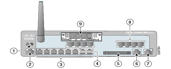
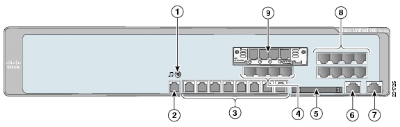
See Figure 2 and Figure 4 for views of the front panels of Cisco Unified 500 Series 8- and 16-user models and Figure 3 and Figure 5 for the 32- and 48-user models.
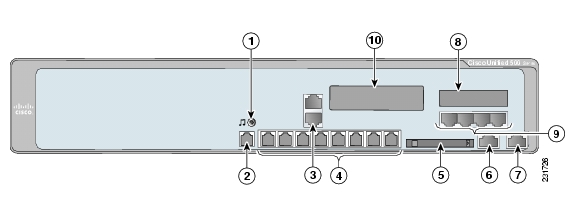
Figure 2 Cisco Unified 500 Series with FXO Ports (8- and 16-user model)
Figure 3 Cisco Unified 500 Series with FXO Ports (32- and 48-user model)
Music-on-hold (MoH) port
WAN port
Console/Aux port
Expansion port
Power over Ethernet (PoE) ports
FXS ports
FXO ports
(Optional) Factory-installed VIC or T1/E1 VWIC
Compact Flash slot
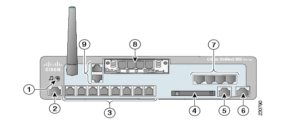
Figure 4
Cisco Unified 500 Series with BRI Ports (8- and 16-user model)
Music-on-hold (MoH) port
Expansion port
Console/Aux port
FXS ports
Power over Ethernet (PoE) ports
(Optional) One factory-installed VIC or T1/E1 VWIC
Compact flash slot
BRI ports
WAN port
Figure 5 Cisco Unified 500 Series with BRI Ports (32- and 48-user model)
Music-o n-hold (MoH) port
WAN port
Console/Aux port
Expansion port
BRI ports
Fixed configuration slot for BRI or FXO (depending on your configuration)
Power over Ethernet (PoE) ports
FXS ports
Compact flash slot
Expansion or fixed configuration slot (depending on your configuration)
Cisco Product Identification Tool
The Cisco Product Identification tool provides detailed illustrations and descriptions showing where to find serial number labels on Cisco products. It includes the following features:
•
•
•
The tool streamlines the process of locating serial number labels and identifying products. Serial number information expedites the entitlement process and is important for access to support services.
Access the Cisco Product Identification tool at http://tools.cisco.com/Support/CPI/index.do.
4 Install Cisco Unified 500 Series Chassis and Power Supply
This section contains basic installation information including the following:
•
•
Safety Information
The Regulatory Compliance and Safety Information document for Cisco Unified 500 Series contains translations of the warnings that appear in this guide.
For safety information you must know before working on a Cisco Unified 500 Series, see the Regulatory Compliance and Safety Information document at Cisco.com.
Warning Definitions
Warning
IMPORTANT SAFETY INSTRUCTIONS
This warning symbol means danger. You are in a situation that could cause bodily injury. Before you work on any equipment, be aware of the hazards involved with electrical circuitry and be familiar with standard practices for preventing accidents. Use the statement number provided at the end of each warning statement to locate its translation in the translated safety warnings that accompanied this device.
Note: Save these instructions.Note: This documentation is to be used in conjunction with the specific product installation guide that shipped with the product. Please refer to the Installation Guide, Configuration Guide, or other enclosed additional documentation for further details. Statement 1071
Warning
High leakage current - permanent earth connection essential before making Telecommunication Network Connection. Statement 343
Warning
Do not work on the system or connect or disconnect cables during periods of lightning activity. Statement 1001
Warning
Read the installation instructions before connecting the system to the power source. Statement 1004
Warning
The plug-socket combination must be accessible at all times, because it serves as the main disconnecting device. Statement 1019
Warning
To avoid electric shock, do not connect safety extra-low voltage (SELV) circuits to telephone-network voltage (TNV) circuits. LAN ports contain SELV circuits, and WAN ports contain TNV circuits. Some LAN and WAN ports both use RJ-45 connectors. Use caution when connecting cables. Statement 1021
Warning
Hazardous network voltages are present in WAN ports regardless of whether power to the unit is OFF or ON. To avoid electric shock, use caution when working near WAN ports. When detaching cables, detach the end away from the unit first. Statement 1026
Warning
Blank faceplates and cover panels serve three important functions: they prevent exposure to hazardous voltages and currents inside the chassis; they contain electromagnetic interference (EMI) that might disrupt other equipment; and they direct the flow of cooling air through the chassis. Do not operate the system unless all cards, faceplates, front covers, and back covers are in place. Statement 1029
Warning
Only trained and qualified personnel should be allowed to install, replace, or service this equipment. Statement 1030
Warning
Never touch uninsulated telephone wires or terminals unless the telephone line has been disconnected at the network interface. Statement 1037
Warning
Avoid using a telephone (other than a cordless type) during an electrical storm. There may be a remote risk of electric shock from lightning. Statement 1038
Warning
Ultimate disposal of this product should be handled according to all national laws and regulations. Statement 1040
Warning
This equipment must be installed and maintained by service personnel as defined by AS/NZS 3260. Incorrectly connecting this equipment to a general-purpose outlet could be hazardous. The telecommunications lines must be disconnected 1) before unplugging the main power connector or 2) while the housing is open, or both. Statement 1043
Warning
To prevent the system from overheating, do not operate it in an area that exceeds the maximum recommended ambient temperature of 40 deg.
Statement 1047Warning
Voltages that present a shock hazard may exist on Power over Ethernet (PoE) circuits if interconnections are made using uninsulated exposed metal contacts, conductors, or terminals. Avoid using such interconnection methods, unless the exposed metal parts are located within a restricted access location and users and service people who are authorized within the restricted access location are made aware of the hazard. A restricted access area can be accessed only through the use of a special tool, lock and key or other means of security. Statement 1072
Warning
No user-serviceable parts inside. Do not open. Statement 1073
The following statement is applicable only in Scandinavian countries.
Warning
This unit is intended for installation in restricted access areas. A restricted access area can be accessed only through the use of a special tool, lock and key, or other means of security. Statement 1017
Installation Guidelines
Before you install a Cisco Unified 500 Series, review the Regulatory Compliance and Safety Information for Cisco Unified Communications 500 Series for Small Business document on Cisco.com.
This platform is a self-contained unit. Do not remove or install any modules or interface cards unless otherwise directed.
When selecting an installation site, observe these guidelines:
•
•
–
–
–
•
Desktop Installation
When installing a Cisco Unified 500 Series and power supply on a desktop, observe the following precautions:
Caution
Caution
To install a chassis on a desktop, table, or other flat surface, place the unit upside-down on a flat surface. Attach the four rubber pads to the recessed areas on the bottom of the unit. Place the unit on a desktop.
Wall-Mounting the Cisco Unified 500 Series (8- and 16-user models only)
You can mount the Cisco Unified 500 Series and power supply for the Cisco Unified 500 Series to a wall or other vertical surface.
Warning
Attaching the Chassis and Power Supply to the Wall
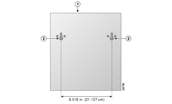
The Cisco Unified 500 Series has two keyholes on the bottom of the chassis for mounting the unit on a wall or other vertical surface. The power supply is mounted to the wall using the wall-mount bracket. To mount the chassis and power supply on a wall, perform the following steps.
Tip
Step 1
Figure 6 Wall-Mount Holes on Bottom of Cisco Unified 500 Series
Step 2
a.
b.
Step 3
a.
b.
Step 4
Figure 7 Wall-Mount Bracket for Power Supply
a.
b.
Step 5
a.
b.
Rack-Mount the Cisco Unified 500 Series
Note
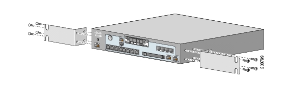
Attach Brackets for Rack-Mounting
To attach the brackets to the Cisco Unified 500 Series, perform the following steps.
Caution
Step 1
Figure 8 Attaching Rack-Mount Brackets to Cisco Unified 500 Series
Step 2
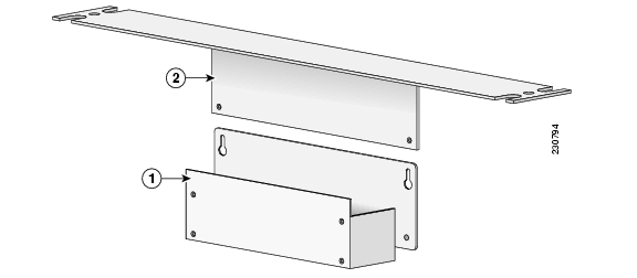
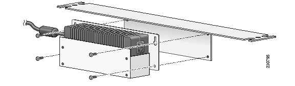
Figure 9 Brackets for Rack-Mounting Power Supply
Step 3
a.
b.
Step 4
Figure 10 Assembling Rack-Mount Kit for the Power Supply
Installing the Cisco Unified 500 Series and Power Supply in a Rack
To mount the chassis and power supply in a 19-inch rack, perform the following steps.
Warning
-- This unit should be mounted at the bottom of the rack if it is the only unit in the rack.
-- When mounting this unit in a partially filled rack, load the rack from the bottom to the top with the heaviest component at the bottom of the rack.
-- If the rack is provided with stabilizing devices, install the stabilizers before mounting or servicing the unit in the rack. Statement 1006
Caution
Note
Tip
Step 1
Step 2
Tip
5 Ground the Chassis
Warning
You must connect the chassis to a reliable earth ground; the ground wire must be installed in accordance with local electrical safety standards.
•
Note
Warning
To connect the chassis to a reliable earth ground, perform the following steps.
Step 1
•
•
Step 2
Step 3
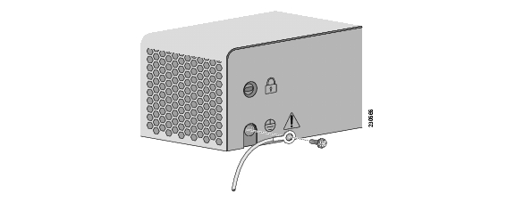
Figure 11 Attaching the Ground to Chassis (8- and 16-User Model)
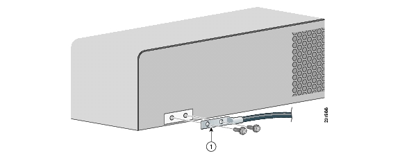
Figure 12
Attaching the Ground to Chassis (32- and 48-User Model)
Step 4
6 Connect Power
Warning
Warning
Warning
To connect the power supply to the Cisco Unified 500 Series, perform the following steps:
Step 1
Step 2
7 Power Up the System
To power up the Cisco Unified 500 Series, perform the following steps:
Step 1
Step 2
Step 3
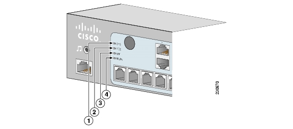
Figure 13
Cisco Unified 500 Series: LEDs
SYS
Solid green
Online
POE
Solid green
Connected
VM
Solid green
Online
WLAN
Blinking green
Connected
8 Create Initial Software Configuration
To use the Cisco Configuration Assistant to create and save the initial software configuration, perform the following steps:
Step 1
Step 2
Step 3
Step 4
a.
b.
Note
c.
Step 5
What to Do Next
The following tasks can be performed in any order:
•
•
•
•
9 Install a Cisco Catalyst Express 520 for a Cisco Unified 500 Series
Before you install the switch, review the information in the Release Notes for the Catalyst Express 520 Switches on Cisco.com.
Before you power on or install the switch, review the safety information in the "Warning Definitions" section and the "Installation Guidelines" section.
The warnings in this chapter are translated into different languages in the Regulatory Compliance and Safety Information for the Catalyst Express 520 Switches document on Cisco.com.
This section contains basic installation information including the following:
•
Warning Definitions
These warnings are translated into different languages in the Regulatory Compliance and Safety Information for the Catalyst Express 520 Switches document that ships with the switch. Review these warnings before you power on or install the switch.
Warning
IMPORTANT SAFETY INSTRUCTIONS
This warning symbol means danger. You are in a situation that could cause bodily injury. Before you work on any equipment, be aware of the hazards involved with electrical circuitry and be familiar with standard practices for preventing accidents. Use the statement number provided at the end of each warning statement to locate its translation in the translated safety warnings that accompanied this device.
Note: Save these instructions.Note: This documentation is to be used in conjunction with the specific product installation guide that shipped with the product. Please refer to the Installation Guide, Configuration Guide, or other enclosed additional documentation for further details. Statement 1071
Warning
This equipment is intended to be grounded. Ensure that the host is connected to earth ground during normal use. Statement 39
Warning
To prevent the switch from overheating, do not operate it in an area that exceeds the maximum recommended ambient temperature of 113ΑF (45ΑC). To prevent airflow restriction, allow at least 3 inches (7.6 cm) of clearance around the ventilation openings. Statement 17B
Warning
Before working on equipment that is connected to power lines, remove jewelry (including rings, necklaces, and watches). Metal objects will heat up when connected to power and ground and can cause serious burns or weld the metal object to the terminals. Statement 43
Warning
Do not stack the chassis on any other equipment. If the chassis falls, it can cause severe bodily injury and equipment damage. Statement 48
Warning
Ethernet cables must be shielded when used in a central office environment. Statement 171
Warning
Do not work on the system or connect or disconnect cables during periods of lightning activity. Statement 1001
Warning
Read the installation instructions before connecting the system to the power source. Statement 1004
Warning
Class 1 laser product. Statement 1008
Warning
The plug-socket combination must be accessible at all times, because it serves as the main disconnecting device. Statement 1019
Warning
This equipment must be grounded. Never defeat the ground conductor or operate the equipment in the absence of a suitably installed ground conductor. Contact the appropriate electrical inspection authority or an electrician if you are uncertain that suitable grounding is available. Statement 1024
Warning
Only trained and qualified personnel should be allowed to install, replace, or service this equipment. Statement 1030
Warning
Ultimate disposal of this product should be handled according to all national laws and regulations. Statement 1040
Warning
For connections outside the building where the equipment is installed, the following ports must be connected through an approved network termination unit with integral circuit protection: 10/100/1000 Ethernet. Statement 1044
Warning
When installing or replacing the unit, the ground connection must always be made first and disconnected last. Statement 1046
Warning
Voltages that present a shock hazard may exist on Power over Ethernet (PoE) circuits if interconnections are made using uninsulated exposed metal contacts, conductors, or terminals. Avoid using such interconnection methods, unless the exposed metal parts are located within a restricted access location and users and service people who are authorized within the restricted access location are made aware of the hazard. A restricted access area can be accessed only through the use of a special tool, lock and key or other means of security. Statement 1072
Warning
No user-serviceable parts inside. Do not open. Statement 1073
Warning
Installation of the equipment must comply with local and national electrical codes. Statement 1074
The following statement is applicable only in Scandinavian countries.
Warning
This unit is intended for installation in restricted access areas. A restricted access area can be accessed only through the use of a special tool, lock and key, or other means of security. Statement 1017
Installation Guidelines
When deciding where to place the Cisco Catalyst Express 520 switch, be sure to observe these requirements:
•
•
•
Note
•
•
•
Note
•
•
–
–
–
–
•
•
Desktop Installation
When installing a Cisco Catalyst Express 520 on a desktop, table, or shelf, observe the following precautions:
Warning
Caution
Caution
Caution
To install the switch on a desktop, table, or shelf, perform the following steps:
Step 1
Step 2
We strongly recommend that you attach the rubber feet to help prevent airflow restriction and overheating.Step 3
Step 4
Step 5
For detailed instructions on using the Cisco Catalyst Express 520 switch, see the User Guide for the Catalyst Express 520 Switches at the following URL:
http://www.cisco.com/en/US/products/ps7238/tsd_products_support_series_home.html
Connect Switch to a Cisco Unified 500 Series
To connect the switch to a Cisco Unified 500 Series, perform the following steps:
Step 1
Step 2
Step 3
a.
b.
Add Switch to Community
In order to alter the initial configuration of the switch, you must add the switch to a community in Cisco Configuration Assistant. To add the switch to the community for this Cisco Unified 500 Series, perform the following steps.
Prerequisites
•
Step 1
Step 2
Step 3
Step 4
a.
b.
10 Connect Interfaces and Devices
This section contains the following topics:
Note
Connect Interfaces
To connect a Cisco Unified 500 Series to a WAN, PSTN, and ISDN, perform the following steps in any order:
Step 1
Step 2
Step 3
Connect Devices
To connect wireless access points, Cisco Unified IP phones, and other devices to a Cisco Unified 500 Series or a Cisco Catalyst Express 520 switch, perform the following steps in any order:
Step 1
Note
The PoE ports on the Catalyst Express 520 provide up to 15.4 W of power to connected Cisco prestandard and IEEE 802.3af-compliant powered devices if the switch detects that there is no power on the circuit. On a per-port basis, you can control whether the PoE port automatically provides power when a powered device is connected by using the Cisco Configuration Assistant. By default, the setting is Auto.The back panel of the Cisco Unified IP phone might have more than one RJ-45 connector. Use the LAN-to-phone connector to connect the phone to the Cisco Unified 500 Series. See the Unified IP Phones 7900 Series Install and Upgrade Guide for your IP phone at http://www.cisco.com/en/US/products/hw/phones/ps379/prod_installation_guides_list.html.
Step 2
Step 3
Step 4
a.
b.
c.
Step 5
a.
b.
c.
11 Verify Communications
To verify communications, perform the following steps.
Step 1
Step 2
Step 3
Step 4
Step 5
a.
b.
c.
d.
e.
Step 6
12 Modify the Software Configuration
This section contains the following topics:
•
•
•
•
•
•
Information About the Software Configuration
This section contains the following topics:
•
Default Software Configuration
The default software configuration on a Cisco Unified 500 Series includes the following preconfigured parameters:
•
•
•
•
Table 8 lists the default values for extensions in a Cisco Unified 500 Series system.
Table 8 Extension Numbers in Default Configuration
Length of directory numbers
3
Pool of extension numbers to be created for analog ports (FXS)
301 to 304
First number in pool of extension numbers to be created. Starting with this directory number, remaining numbers are automatically configured in a contiguous manner.
201
Before deploying the system at the customer site, use the Cisco Configuration Assistant to create and save the initial configuration by accepting the default values. To stage a single-site key system configuration, change the Voice System Type setting from PBX (default) to Key System Configuration.
After deploying the system, use the Cisco Configuration Assistant to personalize the initial software configuration, as required:
•
•
•
•
•
•
•
•
For more information about the Cisco Configuration Assistant, see the online help.
System Management Tools
Table 9 summarizes tools that can be used for modify the software configuration on a Cisco Unified 500 Series before or while deploying the system or for performing routine, ongoing system maintenance.
Table 9 System Management Tools
Primary configuration application for installing and managing Cisco Unified 500 Series. Allows for administration of voice, networking, and security features.
See the Getting Started with Cisco Configuration Assistant at http://www.cisco.com/go/configassist or on the CD-ROM that shipped with the product.
For information about using this tool, see online help.
Web-based application customer administrators to make routine additions and changes associated with employee turnover, such as adding or changing phones and voice mailboxes and managing automated attendant scripts.
Log Into Cisco Unified CME and Cisco Unity Express GUI
For information about using this tool, see online help.
Web-based application for phone users to program a small set of features on their phones.
Log Into Cisco Unified CME Phone User Page
For information about using this tool, see online help.
Cisco Configuration Assistant
The Cisco Configuration Assistant is installed on a PC or laptop that is connected to the Cisco Unified 500 Series by direct connection to a PoE port on the front panel of the platform, by connection to the LAN, or via VPN client.
Use the Cisco Configuration Assistant when staging a Cisco Unified 500 Series system to create and save the initial software configuration or to customize the software configuration for deploying the following system configurations at a customer site:
•
•
•
•
The Cisco Configuration Assistant can be used to personalize software configuration with site-specific values for the following parameters before or while deploying the system at your customer's site:
•
•
•
Before you can use the Configuration Assistant, the application must be installed on a PC or laptop to be connected to the Cisco Unified 500 Series. For information, see the Getting Started with Cisco Configuration Assistant at http://www.cisco.com/go/configassist or on the CD-ROM that shipped with the product.
Cisco Unified CME Phone User Page
The Cisco Unified CME phone user page enables phone users to program a small set of features on their own phones, such as changing speed dial buttons, and to search the Cisco Unified CME directory. Each user must have a unique user name and password that is created by the office administrator.
For information about launching the Cisco Unified CME phone user page, see the "Log Into Cisco Unified CME Phone User Page" section.
GUI for Cisco Unified CME and Cisco Unity Express
The Cisco Unified CME and Cisco Unity Express web-based GUI application enables office administrators to add and change phones, phone user accounts, and voicemail boxes, and to manage automatic attendant (AA) scripts.
For information about logging into this application, see the "Log Into Cisco Unified CME and Cisco Unity Express GUI" section.
Localization Support
A brand new, out-of-the-box, Cisco Unified 500 Series is preloaded at the factory with U.S. English. Cisco Unified CME provides internal localization support for different languages and countries. User locales specify the language to use for text displays; network locales specify country-specific tones and cadences. Cisco Unity Express supports other languages for voice-mail prompts.
Note
For a list of restrictions and supported languages, see the appropriate Cisco Unified 500 Series Matrix at http://www.cisco.com/en/US/products/ps7293/prod_installation_guides_list.html.
Before customizing the software configuration for localization, locale files for Cisco Unified CME and a language pack for Cisco Unity Express must be downloaded from Cisco.com. For information about downloading localization files from Cisco.com, see the Configure Localization Support.
Configure Localization Support
This section contains the following tasks:
•
•
Download Locale Files for Cisco Unified CME from Cisco.com
Before using the Cisco Configuration Assistant to configure localization support for Cisco Unified CME on a Cisco Unified 500 Series, you must download user and network-locale files from Cisco.com.
Note
Prerequisites
•
Step 1
Step 2
CME-locale-language_country-CMEversion
For example, CME-locale-de_DE-4.0.1-1.0 is German for Germany for Cisco Unified CME 4.0(1).
Step 3
Step 4
Step 5
Step 6
Step 7
Download Language for Voice-Mail Prompts from Cisco.com
Before using the Cisco Configuration Assistant to configure localization support for Cisco Unity Express on a Cisco Unified 500 Series, you must download a language pack from Cisco.com.
Note
Prerequisites
•
Step 1
Step 2
cue-vm-language_country-lang-pack.version.prt1
For example, cue-vm-de_DE-lang-pack.2.3.2.prt1 is German for Germany for Cisco Unity Express 2.3.2.
Step 3
Step 4
Step 5
Step 6
Install Cisco Configuration Assistant
To install Cisco Configuration Assistant on a PC to be used to customize the software configuration on a Cisco Unified 500 Series, perform the following steps.
Prerequisites
•
•
•
•
•
Note
Log Into Cisco Unified CME and Cisco Unity Express GUI
To log into this tool as an Administrator for adding or changing phones or voice mailboxes, creating individual phone user accounts, and managing AA scripts, perform the following steps.
Prerequisites
•
•
Step 1
http://ipaddr/ccme.htmlTo access CUE, enter the following URL in the browser window, where ipaddr is the IP address of CUE. Default IP address is: 10.1.10.1
http://ipaddrStep 2
The home window appears. For information, see online help.Log Into Cisco Unified CME Phone User Page
To log into the phone user page for configuring certain features on your own IP phone, such as speed dial and call forward, perform the following steps.
Prerequisites
•
•
Step 1
http://ipaddr/ccme.htmlStep 2
13 Obtaining Documentation, Obtaining Support, and Security Guidelines
For information on obtaining documentation, obtaining support, providing documentation feedback, security guidelines, and also recommended aliases and general Cisco documents, see the monthly What's New in Cisco Product Documentation, which also lists all new and revised Cisco technical documentation at:
http://www.cisco.com/en/US/docs/general/whatsnew/whatsnew.html.
Additional References
The following section provides references related to the Cisco Unified Communications 500 Series for Small Business.
Related Documents
Cisco Smart Business Communications System
Cisco Smart Business Communications System Setup shipped with product or on CD-ROM shipped with product
Product information on Cisco.com at http://www.cisco.com/go/sbcs.
Cisco Configuration Assistant
Getting Started with Cisco Configuration Assistant at http://www.cisco.com/go/configassist or on CD-ROM shipped with product
Cisco Catalyst Express 520 switch
Getting Started Guide for Cisco Catalyst Express 520 shipped with product or on CD-ROM shipped with product.
User Guide for Cisco Catalyst Express 520 at http://www.cisco.com/univercd/cc/td/doc/product/lan/catex520/index.htm or on CD-ROM shipped with product.
Release Notes for Cisco Catalyst Express 520 at http://www.cisco.com/univercd/cc/td/doc/product/lan/catex520/index.htm or on CD-ROM shipped with product.
Cisco Unity Express administrative and user documentation
Cisco Unity Express GUI System Administrator Guide at http://www.cisco.com/en/US/products/sw/voicesw/ps5520/products_administration_guide_book09186a0080679da7.html
Cisco Unity Express Voice-Mail System Quick Start Guide at http://www.cisco.com/application/pdf/en/us/guest/products/ps5520/c1626/ccmigration_09186a008060339a.pdf
Cisco Unity Express Voice-Mail System User Guide at http://www.cisco.com/en/US/products/sw/voicesw/ps5520/products_user_guide09186a00806033eb.html
Cisco Unity Express VoiceView Express Quick Start Guide at http://www.cisco.com/application/pdf/en/us/guest/products/ps5520/c1626/ccmigration_09186a0080678bc6.pdf
User documentation for Cisco Unified IP Phones
Quick Reference Cards at http://www.cisco.com/en/US/products/sw/voicesw/ps4625/products_user_guide09186a008018912b.html
User Guides at http://www.cisco.com/en/US/products/sw/voicesw/ps4625/products_user_guide_list.html
![]()
![]()
![]()
![]()
![]()
![]()
![]()
![]()
Posted: Wed Dec 19 15:13:14 PST 2007
All contents are Copyright © 1992--2007 Cisco Systems, Inc. All rights reserved.
Important Notices and Privacy Statement.