|
|

Table Of Contents
IP Telephony Deployment Models
Benefits of the Single-Site Model
Best Practices for the Single-Site Model
Multisite Implementation with Distributed Call Processing
Benefits of the Distributed Call Processing Model
Best Practices for the Distributed Call Processing Model
Call Processing Agents for the Distributed Call Processing Model
Design Considerations for Section 508 Conformance
IP Telephony Deployment Models
Sections in this chapter address the following topics:
•
Multisite Implementation with Distributed Call Processing
•
Note
Single Site
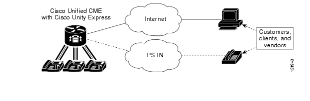
The single-site model for IP telephony consists of a call processing agent located at a single site, or campus, with no telephony services provided over an IP WAN. An SMB would typically deploy the single-site model over single site router running at a single location. In this model, calls beyond the LAN use the PSTN.
The single-site model has the following design characteristics:
•
•
•
•
•
•
•
Figure 2-1 illustrates and example of the model for an IP telephony network within a single campus or site.
Figure 2-1 Single-Site Model
Benefits of the Single-Site Model
A single infrastructure for a converged network solution provides significant cost benefits and enables IP telephony to take advantage of the many IP-based applications in the enterprise. Single-site deployment also allows each site to be completely self-contained. There is no dependency for service in the event of an IP WAN failure or insufficient bandwidth, and there is no loss of call processing service or functionality.
In summary, the main benefits of the single-site model are:
•
•
•
•
Best Practices for the Single-Site Model
Follow these guidelines and best practices when implementing the single-site model:
•
•
•
•
Multisite Implementation with Distributed Call Processing
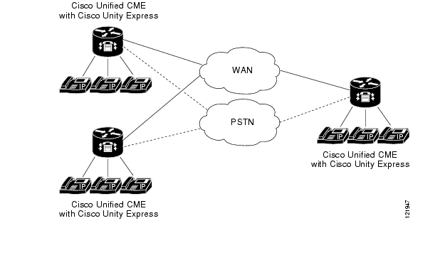
The multisite WAN model with distributed call processing consists of multiple independent sites, each with its own call processing agent connected to a PSTN or an IP WAN (or combination including both) that carries voice traffic between the distributed sites. Figure 2-2 illustrates a typical distributed call processing deployment, featuring an IP WAN interconnection and a backup PSTN connection.
Figure 2-2 A Distributed Call Processing Deployment featuring Cisco Unified CME
Each site in a distributed call processing model can be one of the following:
•
–
–
–
•
•
•
Note
http://www.cisco.com/en/US/products/sw/voicesw/ps4625/products_documentation_roadmap09186a0080189132.htmlAn IP WAN interconnects all the distributed call processing sites. Typically, the PSTN serves as a backup connection between the sites in case the IP WAN connection fails or does not have any more available bandwidth. A site connected only through the PSTN is a standalone site and is not covered by the distributed call processing model. (See Single Site.)
Connectivity options for the IP WAN include:
•
•
•
•
•
•
Benefits of the Distributed Call Processing Model
The multisite WAN model with distributed call processing provides the following benefits:
•
•
•
•
•
Best Practices for the Distributed Call Processing Model
A multi-site deployment with distributed call processing has many of the same requirements as a single site or a multi-site deployment with centralized call processing. Follow the best practices from these other models in addition to the ones listed here for the distributed call processing model.
Gatekeeper or Session Initiation Protocol (SIP) proxy servers are among the key elements in the multi-site WAN model with distributed call processing. They each provide dial plan resolution, with the gatekeeper also providing call admission control. A gatekeeper is an H.323 device that provides call admission control and E.164 dial plan resolution.
The following best practices apply to the use of a gatekeeper:
•
•
•
•
•
SIP devices provide resolution of E.164 numbers and SIP uniform resource identifiers (URIs) to enable endpoints to place calls to each other. Cisco Unified CallManager supports the use of E.164 numbers only.
The following best practices apply to the use of SIP proxies:
•
•
•
Call Processing Agents for the Distributed Call Processing Model
Your choice of call processing agent will vary, based on many factors. The main factors, for the purpose of design, are the size of the site and the functionality required.
For a distributed call processing deployment, each site has its own call processing agent. The design of each site varies with the call processing agent, the functionality required, and the fault tolerance required. For example, in a site with 500 phones, a Cisco Unified CallManager cluster containing two servers can provide one-to-one redundancy, with the backup server being used as a publisher and TFTP (Trivial File Transfer Protocol) server.
The requirement for IP-based applications also greatly affects the choice of call processing agent because only Cisco Unified CallManager provides the required support for many Cisco IP applications.
Table 2-1 lists recommended call processing agents.
Design Considerations for Section 508 Conformance
Regardless of which deployment model you choose, you should consider designing your IP telephony network to make the telephony features more accessible to users with disabilities, in conformance with Section 255 of the Telecommunications Act and U.S. Section 508.
Observe the following basic design guidelines when configuring your IP telephony network to conform to Section 508:
•
•
•
•
•
•
–
Plug a TTY/TDD with an RJ-11 analog line option directly into a Cisco FXS port. Any FXS port will work, such as the one on a Cisco Unified IP Phone 7900 Series or on the Cisco VG224, Catalyst 6000, Cisco ATA 188 module, or any other Cisco voice gateway with an FXS port. We recommend this method of connection.
–
Place the IP phone handset into a coupling device on the TTY/TDD. Acoustic coupling is less reliable than an RJ-11 connection because the coupling device is generally more susceptible to transmission errors caused by ambient room noise and other factors.
•
![]()
![]()
![]()
![]()
![]()
![]()
![]()
![]()
Posted: Thu Sep 14 16:46:05 PDT 2006
All contents are Copyright © 1992--2006 Cisco Systems, Inc. All rights reserved.
Important Notices and Privacy Statement.