|
|

Table Of Contents
Cisco IOS PSTN Telephony Interfaces
PSTN Trunks Integrated with or Separate from Cisco Unified CME
PSTN Call Switching with DID Enabled
PSTN Call Switching with DNIS (No DID)
PSTN Call Switching with No DNIS (FXO Trunks)
Cisco Unified CME dialplan-pattern Command
Voice Gateways
Router PSTN connectivity is generically referred to as voice gateway functionality, offering a gateway for voice over IP (VoIP) calls to, and from, traditional analog or digital PSTN or private branch exchange (PBX) calls. You can use a router voice gateway to connect to PSTN central office (CO) switches, private branch exchanges (PBXs), Key Systems, time-division multiplexing (TDM)-based interactive voice response (IVR) systems, traditional TDM-based voice mail systems, and any other legacy (non-IP) voice processing or telephone equipment.
This chapter explores several aspects of Cisco Unified CallManager Express (Cisco Unified CME) connectivity to the PSTN, including the following:
•
Standards-based telephony signaling systems and protocols supported by Cisco IOS, which, in turn, determine what traditional TDM or analog systems to which you can connect and what features you get when using this type of connection
•
•
•
Traditional telephony terminology is used throughout this chapter. It has a more precise meaning here than in other chapters, because the topic of discussion is connecting a traditional telephony system, the PSTN.
Voice gateway considerations for Cisco Unified CME deployment are in the following sections:
•
Note
Trunk Signaling Systems
Cisco IOS PSTN connectivity complies with the relevant standard signaling systems used by the PSTN and other telephony-switching systems. Cisco IOS routers support most signaling variations in general use. No matter where your business is located, you should be able to connect easily to the PSTN with the analog or digital signaling options described in this section.
Analog Signaling
Low-density PSTN connectivity typically implies an analog connection. In some geographies Basic Rate Interface (BRI) is used instead, as discussed in the "Digital Signaling" section. Analog signaling is also used for connections to analog stations (such as fax machines and traditional analog phones). Table 4-1 summarizes the analog signaling variations supported by Cisco IOS voice gateways.
To connect your Cisco Unified CME system to the PSTN for normal analog business line service, use FXO interfaces. FXO ports, like all the other analog interfaces, carry one call per port, so each RJ-11 port on your Cisco Unified CME router connects to one line from the PSTN and carries a single call at a time. A second call is given a busy tone if it tries to use the same port or line.
Note
The FXS and FXO voice interfaces are asymmetric, but most of the other signaling methods are symmetric. This means that if the PSTN offers an FXS interface (a normal business line), your Cisco Unified CME router connects to that with an FXO interface. On the other hand, you might have a Key System with FXO interfaces being used to connect to the PSTN. If you want to connect those same ports to your Cisco Unified CME router, you will require FXS interfaces on the router to connect to these ports.
Asymmetric also means that although you can make calls in both directions across FXS and FXO connections, services typically work in only one direction. For example, caller ID is sent on an FXS interface and received on an FXO interface, but not the other way around.
Analog trunks all support a single call per physical connection or port, so you need as many ports connected to the PSTN as you require simultaneous calls from your business to the PSTN.
FXO connections do not provide dialed digits (DNIS), introducing challenges in providing automatic call switching. More information about this is provided in the "PSTN Trunk Failover" section. Analog DID is a variation of FXO that provides DNIS on what is, essentially, an FXO interface. Note, though, that these trunks are one-way and can only receive calls from the PSTN (they cannot make calls to the PSTN). If you use analog DID for incoming calls from the PSTN, you still need FXO trunks as well to be able to make outgoing calls to the PSTN.
Digital Signaling
If you require only a small number of simultaneous calls to the PSTN, you will most likely use analog FXO connections. In geographic locations outside North America, ISDN BRI is a likely alternative option for low-density PSTN connectivity. However, if you have a larger office and require more than approximately 10 to 16 simultaneous calls to the PSTN, a digital T1 or E1 trunk might provide a more cost-effective option. Table 4-2 summarizes the digital signaling variations supported by Cisco IOS routers.
BRI connectivity on the Cisco IOS routers is supported only for switch (PSTN, PBX, or key system) connectivity—not for ISDN BRI phones.
All ISDN variations listed in Table 4-2 support both DID and caller ID, which is implicitly supported in the ISDN protocol. The CAS protocols (T1 CAS and E1 R2) might or might not support caller ID. Typically T1 CAS does not, but T1 FGD is a variation that does. All digital trunk types support DNIS and DID.
Cisco IOS PSTN Telephony Interfaces
You can add numerous modular cards to your Cisco Unified CME router to support PSTN connections of the types discussed in the preceding section. These technologies and hardware cards are not particular to Cisco Unified CME. They can be used on any Cisco router that supports the card in question—independent of whether Cisco Unified CME is enabled on the router. For example, you can choose to have two separate routers in your office—one configured for Cisco Unified CME and the other as the PSTN voice gateway—as an alternative, or you can combine both functions in the same router.
The following sections cover these hardware choices in greater detail:
•
Analog Trunks
Voice interfaces range from two- and four-port FXO/FXS/E&M/DID cards up to 96/120-channel quad T1/E1 interfaces. The physical telephony interface for analog and BRI ports is provided by a plug-in voice interface card (VIC) and for a T1/E1 port by a voice or WAN interface card (VWIC).
Using various combinations of VICs and VWICs on a Cisco IOS router, you can build a Cisco Unified CME system that includes a range of physical telephone interfaces. You can assemble a small analog telephony system with a few FXO ports used to connect to PSTN subscriber lines, or you can use digital telephony interfaces such as T1/E1 and ISDN BRI/PRI, or any combination of these. The specific hardware cards offering analog trunk and station (analog phone or fax machine) interfaces are discussed next.
Analog Trunk and Station Hardware
The analog interface cards listed in Table 4-3 are used to provide low-density analog PSTN interfaces. VICs are placed in a Voice Interface Card (VIC) or WAN interface card (WIC) slot (supported on the Cisco 1751 and Cisco 1760), in a high-speed WIC (HWIC) slot on the router (supported on the Cisco 2800 and Cisco 3800 series), or inside a network module (Cisco 2600, Cisco 2800, Cisco 3700, and Cisco 3800 series) such as the NM-HD-1V, NM-HD-2V, NM-HD-2VE, or NM-HDV2. For high-density analog PSTN interfaces, the NM-HDA (supported on the Cisco 2600, Cisco 2811, Cisco 2821, Cisco 2851, Cisco 37xx, and Cisco 38xx) or the EVM-HD-8FXS/DID card (supported on the Cisco 2821, Cisco 2851, and Cisco 38xx) can be used.
The cards that support multiple signaling systems (such as FXS or DID, and FXO or CAMA) can be software configured on a per-port basis to support one or the other. For example, the VIC2-4FXO card can be configured to support one CAMA and three FXO ports, or two CAMA and two FXO ports.
Configuring Analog Trunks and Stations
All PSTN interfaces are configured as voice ports on the router. When you insert the card into the router, the configuration automatically creates and shows the corresponding voice ports. Directing calls to a voice port is based on the dial plan and is implemented with plain old telephone service (POTS) dial peers.
Note that the use of the 9T directive in the destination-pattern command of the dial peer in the following example configuration:
dial-peer voice 100 potsdescription PSTNdestination-pattern 9Tport 1/0/0dial-peer voice 100 potsdescription PSTNdestination-pattern 9Tport 1/0/1This command is a quick way of dealing with variable-length PSTN dial plans. The T denotes a timeout. The command destination-pattern 9T instructs the dial peer to match any dialed digits that start with a nine, regardless of how many digits follow. When the timeout expires, the digits are forwarded from the voice port to the PSTN. There are other, more explicit ways to make your destination-pattern commands match calls to the PSTN more exactly, including 9911, 9411, 91T, and 9[2-9].
The dial peers shown in the following configuration example direct all calls (of a varying number of digits) that start with a nine to the two PSTN FXO trunks, ports 1/0/0 and 1/0/1. If no preference is given on the dial peers and both trunks are free, the Cisco IOS software chooses one of the two trunks based on an internal algorithm that considers idle times and usage of the trunks. You can control the order in which they are chosen by adding a preference command to the dial peer. The dial-peer hunt command offers additional control over the sequence in which dial peers, and therefore voice ports, are chosen.
You can also direct calls to different destinations over different trunks if required. This is shown in the following example, where calls to the 408 area code always use voice port 1/0/0, and calls to the 415 area code always use voice port 1/0/1:
voice-port 1/0/0voice-port 1/0/1dial-peer voice 100 potsdescription PSTNdestination-pattern 9408.......port 1/0/0dial-peer voice 101 potsdescription PSTNdestination-pattern 9415.......port 1/0/1The preceding example illustrates how you can connect to each independently and direct different types of calls to the correct trunks, if you have different local and long-distance PSTN provider connections.
If you require CAMA connectivity to comply with North American emergency calling regulations, you can configure one or more of your FXO ports for CAMA operation. This is shown in the following example, where port 2/0/3 on a VIC2-4FXO card is configured for CAMA signaling. The following example configuration illustrates this command usage:
voice-port 2/0/0voice-port 2/0/1signal ground-startvoice-port 2/0/2voice-port 2/0/3signal cama KP-NPD-NXX-XXXX-ST
Note
Analog Trunk Features
With analog FXO interfaces, caller ID information received for an incoming PSTN call is displayed on the IP phones. You can optionally enable the Flash softkey on your IP phones. Pressing the Flash softkey on the IP phone generates a hookflash signal on the FXO port and allows you to exercise PSTN subscriber line services, such as PSTN call waiting and three-way calling. However, Cisco IOS FXO ports do not support PSTN call waiting caller ID display.
You can also set up a direct link between a specific PSTN telephone line and an individual button on an IP phone. This is useful if you want to use PSTN-based voice mail services where a stutter dial tone on the PSTN line indicates that a message is waiting.
As mentioned earlier, in the "Analog Signaling" section. FXO interfaces are asymmetric. As such, calls can be disconnected in only one direction in pure FXO operation. The historic reasons for this are beyond the scope of this publication. Suffice it to say that today FXO ports are widely used as two-way trunks, and special care must be taken that calls disconnect properly in both directions and do not hang the port. You can use the following Cisco IOS commands on the voice port to facilitate proper call disconnect on FXO ports:
•
•
•
•
The selection of a particular command depends on the complementary features provided by your PSTN CO switch. It also varies based on geographic location and the technology available in the CO.
In addition, FXO signaling does not receive dialed digits (DNIS). This means that an incoming call from the PSTN to an FXO port cannot be switched automatically by your Cisco Unified CME system to an extension, because there are no digits from the PSTN to tell Cisco Unified CME where to switch it. You can overcome this shortcoming of FXO signaling by using auto-terminate directives on the FXO voice port to switch the call to a predetermined destination. Commands you can explore include connection plar and connection plar-opx, which are described in the "PSTN Call Switching" section.
Digital Trunks
Digital trunks can be low-density (for example, BRI with two calls per port) or high-density (such as T1 or E1 ports with 24 or 30 calls per port, respectively). The specific hardware cards offering digital trunk interfaces are discussed in the following sections.
Digital Trunk Hardware
The digital interface cards listed in Table 4-4 are used to provide a range of low- to high-density digital PSTN interfaces.
In the general case, a T1 port offers 24 voice channels, and an E1 port offers 30 voice channels. When using ISDN signaling, where one channel is dedicated to call control signaling (the D channel), a T1 carries 23 voice channels, and an E1 carries 30 voice channels. (An E1 always has a channel dedicated to signaling, no matter what type of protocol is used. With T1 this is not normally the case; using ISDN takes away one of the standard channels.)
You might not use the maximum number of channels on these ports, depending on what your PSTN service provider offers. You can configure your Cisco IOS router with any number of channels on the T1 or E1 interface, but it must be complemented by what is configured on the PSTN CO on the other side.
Fractional T1 service is quite common in North America and allows you to subscribe to PSTN T1 service with, for example, only 12 or 16 channels of service (and this service costs less than a full T1 of 24 channels). This service can be either T1 CAS or T1 PRI. Another service is to multiplex your WAN connection (Frame Relay or Point-to-Point Protocol [PPP]) on some channels of the same physical T1 used for your PSTN voice connection. For example, channels 1 to 6 could offer a 384-Kbps PPP WAN connection; channels 10 to 20 could offer ten channels of PSTN voice service using T1 E&M signaling.
Fractional E1 service is much less common. Your lower-density PSTN connectivity options in geographies that use E1 connectivity may be multiples of BRI until such time as a full E1 makes sense for your business.
Configuring Digital Trunks
Digital PSTN interfaces are configured in general just like analog interfaces—that is, as voice ports and POTS dial peers on the router to direct calls to the ports. The dial peer control and configuration are exactly the same, regardless of what type of voice port used.
T1/E1 ports, however, show up as controllers in a basic configuration (by just inserting the hardware into the router). Unlike an analog interface, the voice port is not created until you add more configuration details to the controller. T1/E1 ports are used for both data and voice access. Until you add specific configuration statements, the router does not know what your intention is with the T1/E1 port. Add a voice configuration to a T1/E1 port by using either the ds0-group, tdm-group, or pri-group command. A data T1/E1 port is configured with the channel-group command.
You often see the terms CAS and common channel signaling (CCS) when reading about T1/E1 trunks. CAS generally means that the signaling to control the call uses the same channel (or timeslot) as the call's media path. This is common on T1 interfaces. (It is also called robbed-bit signaling because a few bits out of the 64-kbps channel are "stolen" from the media path to convey call control information, such as on-hook and off-hook.) CCS means that a channel is dedicated to signaling. This channel carries the call control information for all the voice calls (media paths) on that same T1/E1 interface. For example, channel 16 on an E1 is used exclusively for call control and carries the control information for all the other channels (1 to 15 and 17 to 31) on that interface.
The following configuration example illustrates a T1 CAS (E&M immediate start) PSTN connection using a ds0-group configuration. In this example, you can see that the second port on the VWIC shows up as controller T1 2/1. This means that the hardware has been detected but no configuration has been done for this port
controller T1 2/0framing esfclock source internallinecode b8zsds0-group 0 timeslots 1-24 type e&m-immediate-startcontroller T1 2/1voice-port 2/0:0signal immediatedial-peer voice 100 potsdescription PSTNdestination-pattern 9Tport 2/0:0In this example, all 24 channels on the T1 are configured. But you could as easily have stated ds0-group 0 timeslots 1-10 if you agreed with your provider to get only ten channels of PSTN service on this T1 (fractional T1 service). The result of the ds0-group command is that voice port 2/0:0 is created. The POTS dial peer, in this example, looks the same as the one in the FXO example earlier, except that it now points to voice port 2/0:0, which is a T1 port.
Note
If you are using ISDN PRI service to the PSTN, you use the pri-group command to insert a voice configuration on a T1 or E1 controller. The following configuration example shows a sample configuration for a T1 PRI trunk.
isdn switch-type primary-5esscontroller T1 2/0framing esflinecode b8zspri-group timeslots 1-24interface Serial2/0:23no ip addressisdn switch-type primary-5essisdn incoming-voice voicevoice-port 2/0:23echo-cancel coverage 64dial-peer voice 100 potsdescription PSTNdestination-pattern 9Tport 2/0:23Geographic variants of ISDN are controlled by the switch-type setting. A default router setting, seen in the preceding example as the first line in the configuration, is specified at the Cisco IOS global level (the isdn switch-type command). This default can be overridden on a per-interface basis by the switch-type statement under the controller. In the preceding example, both are set to primary-5ess, but they could be different. If they are different, the statement on the controller takes precedence.
The D- channel interface (interface Serial 2/0:23) and voice-port (voice-port 2/0:23) commands are automatically created by the insertion of the pri-group command on the controller. The POTS dial peer again looks exactly the same as in previous examples. You must adjust the voice port to which it refers.
Digital Trunk Features
For PRI/BRI interfaces using ISDN signaling, you can optionally allow the IP phone's full DID name and number to be used as the calling party's identity for outgoing calls. This puts extension-specific information into the PSTN billing records for the call. This can be useful if you want to rely on the PSTN provider's billing information to track the internal origin point of PSTN calls made from your Cisco Unified CME system. Alternatively, you can block IP phone extension-specific information from the outgoing ISDN call and instead substitute the general public phone number for your system.
Generally, PSTN providers do not use name information delivered to the PSTN by a subscriber system. Although the name can be included in the ISDN call setup, the PSTN typically overrides this with the information associated with the subscriber in the PSTN's own databases. You can, however, receive name display information from the PSTN on ISDN trunks, and display this on the IP phones in your business.
All digital trunks provide DID (or DNIS) information. ISDN trunks also provide caller ID delivery. Fractional CAS and PRI are supported on the Cisco IOS routers. If you configure fractional PRI, the D channel for the T1 must be on channel 24 and for E1 on channel 16. This cannot be customized. The voice channels (B channels) can be any subset of the remaining channels.
ISDN channels cannot be customized to be incoming only or outgoing only. However, through creative use of dial peers, you can limit the number of incoming or outgoing calls to and from your business. You cannot specify the exact channel each call should use. With T1 CAS, you have more granular control, because you can specify separate ds0-groups (up to a ds0-group per channel). Each ds0-group creates a separate voice port that you can control via dial peers as to what calls may reach those channels. The following configuration example illustrates this feature.
controller T1 2/0framing esfclock source internallinecode b8zsds0-group 0 timeslots 1-10 type e&m-immediate-startds0-group 1 timeslots 15-20 type e&m-immediate-startcontroller T1 2/1voice-port 2/0:0signal immediatevoice-port 2/0:1signal immediatedial-peer voice 100 potsdescription PSTNdestination-pattern 9408.......port 2/0:0dial-peer voice 101 potsdescription PSTNdestination-pattern 9415.......port 2/0:1The ds0-group 0 timeslots 1-10 command results in voice port 2/0:0, and the ds0-group 1 timeslots 15-20 command creates voice port 2/0:1.
DSP Hardware
Digital signal processor (DSP) technology provides voice compression, echo cancellation, tone generation, and voice packetization functions for servicing voice interfaces and converting the voice for transport over packet networks. To drive a PSTN voice connection, the analog or digital voice port must have access to a DSP for the call.
Some voice NMs include internal slots into which DSP modules can be plugged, and others have fixed DSP configurations. In some router models, such as the Cisco 1760, Cisco 2800, and Cisco 3800 series, you can plug DSP cards directly into the router's motherboard.
VWIC cards offer only physical T1/E1 port connections, and VIC cards offer only the physical analog or BRI ports. If a VIC or VWIC card is inserted into a router WIC slot (supported on the Cisco 1751, Cisco 1760, Cisco 28xx, and Cisco 38xx), the DSPs are typically provided by the onboard DSP cards. A VIC or VWIC inserted into an NM typically draws on DSPs resident on the NM itself.
One other variation is to use a VWIC in a WIC slot on the Cisco 2600 or Cisco 3700 series platforms, which do not support onboard DSPs. For this configuration, you can use a DSP AIM card such as the AIM-VOICE-30 or the AIM-ATM-VOICE-30 card. An Advanced Integration Module (AIM) is an internal plug-in module that fits on the router's motherboard. The AIM-based DSPs cannot drive analog or BRI VIC cards, only T1/E1 VWICs.
DSP cards for motherboard and NM-based slots come in many densities and use various DSP technologies. All are called packet voice/fax DSP module (PVDM) cards.
PSTN Trunks Integrated with or Separate from Cisco Unified CME
In a typical deployment, the PSTN connectivity for your business is integrated into your Cisco Unified CME router. However, you could also use a separate router platform as your PSTN gateway. You may choose to do this because you already have a router that acts as your PSTN gateway in your office or because the slot density on your Cisco Unified CME router is insufficient for the PSTN connectivity your office requires.
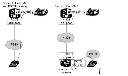
For PSTN trunks integrated onto your Cisco Unified CME router, the voice call is switched directly from the POTS interface to the IP phone and is straightforward to configure. Placing the PSTN gateway on a different platform gives you an H.323 (or SIP) call leg between the PSTN gateway and the Cisco Unified CME call controller where the IP phones are managed. This requires POTS dial peers on the PSTN gateway to direct calls to the PSTN interfaces, as shown in the previous configuration examples in this chapter. It requires H.323 dial peers to direct calls from the PSTN gateway to IP phones and from the IP phones to the PSTN gateway. From an H.323 standpoint, this configuration is similar to connecting two separate Cisco Unified CME systems via an H.323 VoIP interface between them. This is shown in Figure 4-1.
Figure 4-1 Integrated or Separate PSTN Gateways
We recommend that you deploy Cisco Unified CME with an integrated PSTN gateway, because this approach results in a much simpler network design and configuration. If Cisco Unity Express is used for the automated attendant (AA) or voice mail on your Cisco Unified CME system, the H.323 VoIP leg must be converted to a SIP call leg before the call can successfully terminate on the Cisco Unity Express application. For this type of implementation, we recommend Cisco Unified CME 3.2 because with Cisco Unified CME 3.2 and later, you can use the Cisco IOS translation shown in the following configuration example.
voice service voipallow-connections h323 to sipPSTN Call Switching
The preceding sections explored the various PSTN trunk types, signaling methods, and router hardware you can use to connect to the PSTN. But there are more considerations than just physical connectivity. One thing to keep in mind is that the PSTN numbers and your internal extension numbers are almost certainly not the same, at least not the same length. Digit translation must occur to map one set of numbers to another. You will learn more about this in the "Digit Manipulation" section.
Another consideration is what PSTN numbers (and how many) your business has or needs. Do you have just one main office number, and the receptionist directs all calls to the correct employee? Do you need an AA menu to have callers switch to the person or service they want to speak to? Should you have DID numbers for all or some of your employees? Do you prefer a Key System type of operation, where a series of PSTN numbers appear as distinct line appearances on a number of phones, and any employee can pick up any call? There is interaction between your business needs, the PSTN service you get from your provider, the capabilities of the physical connection to the PSTN, and the Cisco Unified CME configuration (IP phone button appearances) to use.
The physical connection is likely dictated by cost, your office's geographic location, and the number of voice channels your office needs. You might want DID service for your business. However, if it is not offered in your area at a cost-effective level, you have little choice but to implement for non-DID service.
The following sections explore considerations about how calls may be routed depending on whether you have DID service and how you can handle calls to non-DID destinations within your business:
•
•
•
PSTN Call Switching with DID Enabled
Many offices deploying Cisco Unified CME have DID capability from the PSTN provider for some subset of employees. PSTN calls to DID destinations can be switched automatically to the employee's phone without any manual intervention.
There are two situations to consider, depending on how DID numbers are allocated to destinations within your business:
•
–
–
–
•
–
–
–
PSTN Call Switching with DNIS (No DID)
PSTN call switching with DNIS and no DID is not a likely configuration, but it is possible. In this configuration, your business does not have DID service and, therefore, has only a single main office number from the PSTN provider although you have multiple trunks. Or even if you have multiple PSTN numbers, they are not associated with particular employees, but instead are just alternate main office numbers.
Although the dialed number is delivered via DNIS from the PSTN to the PSTN gateway, it is of little use to switch calls to individual destinations. In this situation, you have two configuration choices:
•
•
If all calls are directed to the AA (or a receptionist), caller-busy conditions must be carefully considered. For example, you need to determine what should happen if all AA ports are busy or all the receptionists are busy. If you do not want busy tone returned, more ports or receptionists may be required, or alternate destinations to switch calls to (lower-preference dial peers) or DID service may be needed for high-volume destinations in your business.
PSTN Call Switching with No DNIS (FXO Trunks)
If the office has only FXO trunks, no DNIS (or DID) capability is technically possible. This scenario is very common for a small standalone office or a small branch of a bigger network that has only a few business lines from the local CO.
Because no dialed digits (DNIS) are available on FXO trunks, these calls must be autoterminated on a predetermined destination (most often the AA or the receptionist's extension) — or these calls must ring all phones that have the line appearance on them (in Key-system mode). This can be achieved with a private line automatic ringdown (PLAR) configuration on the voice port where a particular destination extension is associated with the trunk, and all calls arriving on that trunk are switched as if they had dialed the configured extension. This syntax is shown in the following configuration example, where all calls arriving on the FXO trunk on slot 1/0/0 are switched as if they had dialed extension 6800.
voice-port 1/0/0connection plar opx 6800Most small offices have multiple FXO trunks to the PSTN because each trunk can carry only a single call. One or more PSTN numbers may be associated with these trunks or this trunk group, depending on the PSTN service the business subscribes to. Generally, there are two possibilities:
•
•
Sharing all FXO trunks across all PSTN calls (the first case in the preceding list) results in better trunk utilization than assigning distinct FXO trunk(s) to the main office number and other distinct FXO trunk(s) to the voice mail pilot number (the second case).
Digit Manipulation
There are various reasons to manipulate the digits dialed by the caller on a voice system. The most common reason is to allow both internal calls (from other extensions) and external calls from the PSTN (where a full E.164 phone number is delivered) to terminate directly on the user's phone without needing a receptionist to intercept and redirect the call.
Note
Here are some other reasons to translate (or manipulate) digits:
•
•
•
•
•
For example, suppose your employee, UserU1, is at extension 3001, and her PSTN DID number is 4xx-5yy-3001. Without some form of digit manipulation or live intercept, a call incoming from the PSTN that dialed 4xx-5yy-3001 will not match the ephone-dn definition for UserU1's phone, which contains only her extension, 3001. Therefore, a method is needed to translate the string 4xx5yy3001 to 3001.
Several Cisco IOS digit manipulation tools can translate phone numbers. The following are the most common:
•
•
•
Dial Peer Commands
You can include several commands on a POTS dial peer to add, suppress, or substitute the digits forwarded to the PSTN trunk interface:
•
•
•
•
•
•
Dial peer commands are useful if only small changes to the beginning or end of the dialed number are necessary, such as prefixing an area code, prefixing a CO designator (NXX) to an extension number, or forwarding only the last four digits of a longer number. The wildcard matching within the destination-pattern command automatically deletes the numbers explicitly matched. For example, when 5yy3001 is dialed and is matched by a dial peer that contains the command destination-pattern 5yy...., the default operation is to forward only the digits 3001.
Note
Cisco IOS Translation Rules
For more extensive digit manipulation, such as a wholesale change of a number or substituting digits in the middle of a number, translation rules are much more powerful. Translation rules are regular expressions attached to the dial peer with the translation-profile command.
Note
Like the other dial peer commands discussed in the preceding section, translation rules are a generic Cisco IOS feature that allows manipulation of called numbers, calling numbers, and number types. It can also be attached in such a way that it translates calls in only one direction, either incoming or outgoing.
The following example illustrates configuration commands for a T1 PRI trunk, with translation profile to_261x attached for incoming calls (calls from the PSTN to the Cisco IOS PSTN gateway). Translation profile to_261x, in turn, references translation rule 23, which has ten rules specified. This CLI segment intercepts all calls incoming from the PSTN over this T1 PRI that contains a dialed number ending in the range 12610 to 12619. It does not matter what (or how many) numbers precede this range; for example, it could be 5xx-3y1-2610 or 5y1-2618. The numbers that match the rule (12610 to 12619) are translated to a completely unrelated number so that none of the original digits survive. To illustrate, if a call with a dialed number of 5xx-3y1-2610 arrives, it is translated to 32085, and an IP phone (or other dial peer) associated with that extension receives the call. A PSTN call with a dialed number of 5y1-2618 results in extension 79988 receiving the call.
voice translation-rule 23rule 1 /12611/ /37002/rule 2 /12612/ /37262/rule 3 /12613/ /37990/rule 4 /12614/ /57514/rule 5 /12615/ /30631/rule 6 /12616/ /50043/rule 7 /12617/ /28787/rule 8 /12618/ /79988/rule 9 /12619/ /68278/rule 10 /12610/ /32085/voice translation-profile to_261xtranslate called 23controller T1 2/0framing esflinecode b8zspri-group timeslots 1-24interface Serial2/0:23no ip addressno logging event link-statusisdn switch-type primary-5essisdn incoming-voice voicevoice-port 2/0:23echo-cancel coverage 64dial-peer voice 1261 potstranslation-profile incoming to_261xincoming called-number 1261.direct-inward-dialport 2/0:23The syntax for translation rules can be cryptic if you are unfamiliar with regular expressions, but these rules can provide a powerful facility to manipulate digits. Translation rules are not tied to Cisco Unified CME, so you can use it on any Cisco IOS voice-enabled router.
Here are some considerations when using the Cisco IOS voice translation rules feature:
•
•
•
•
•
When applying translation rules to ephone-dns, there is a side effect that if no rule is matched, an extra post-dial delay is incurred. As a workaround, create a dummy translation rule that acts as a pass-through. For example, if no rule is applied to extension-to-extension calls, and the extensions all start with 5, add a rule that "translates" 5 to 5, just to make sure that a rule is always matched, and the delay is not incurred.
Cisco Unified CME dialplan-pattern Command
The Cisco Unified CME dialplan-pattern command allows E.164 numbers to be mapped to extension numbers or, put another way, to extract the extension number from a longer DID number. The dialplan-pattern command does not actually translate the number (although the result from a call routing point of view is the same). It instead creates multiple dial peers that allow different dialed numbers to terminate on the same phone.
The dialplan-pattern command can be used in some cases (calls to IP phones) to achieve the same call routing as can be achieved by using translation rules. Because these two features operate differently, you should think carefully about which method to use. If you use both methods, you should be clear about how these might interplay with each other to affect your call routing. The dialplan-pattern command is explained in more detail in "Connecting Multiple Cisco Unified CallManager Express Systems with VoIP."
The CLI shown in the following example illustrates the same mapping as the number translation discussed previously for employee UserU1.
telephony-serviceload 7960-7940 P00303020214max-ephones 48max-dn 192ip source-address 10.1.3.1 port 2000system message CUE System 2691create cnf-files version-stamp 7960 Jul 15 2003 13:48:12dialplan-pattern 1 510395.... extension-length 4voicemail 6800max-conferences 8web admin system name cue password cuedn-webedittime-webeditSome considerations about using the Cisco Unified CME dialplan-pattern feature include the following:
•
•
•
•
•
•
PSTN Trunk Failover
Larger offices that use a digital trunk, such as a PRI, often need a backup method to connect to the PSTN. This requirement results in the PRI being the main PSTN connection point in addition to FXO trunks (typically used to back up a T1) or BRI interfaces (typically to back up an E1) used if the main interface is down.
In this configuration, the dial peers directing calls to the main interface must be duplicated to also point to the backup interface. You can prioritize calls to use the main interface when it is available by using the preference command on the dial peers pointing to these trunks.
Another need is to have a backup mechanism for a small office with FXO trunks if a power failure occurs. FXO hardware supports a feature called FXO Power Failover that allows a hardware (relay) connection between a red phone (a specially dedicated analog telephone in your office that normally is not in use) and the PSTN line, in case the router is not powered.
On Cisco voice hardware, the NM-HDA-4FXS FXO expansion card (the EM-HDA-4FXO) and the EVM-HD-8FXS/DID FXO expansion card (the EM-HDA-6FXO) each have one port per card that has this power failover capability. Other Cisco FXO hardware cards do not support this feature.
Note
![]()
![]()
![]()
![]()
![]()
![]()
![]()
![]()
Posted: Thu Sep 14 17:48:50 PDT 2006
All contents are Copyright © 1992--2006 Cisco Systems, Inc. All rights reserved.
Important Notices and Privacy Statement.