|
|

This document explains how to install memory modules, packet voice/data modules (PVDMs), and Virtual Private Network (VPN) modules on analog station interface 81 (ASI 81) cards, ASI 160 cards, multiservice route processor 200 (MRP) cards, system processing engine 200 (SPE 200) cards, and SPE 310 cards in the Cisco Integrated Communications System 7750, referred to from this point as the ASI 81, ASI 160, MRP 200, SPE 200, SPE 310, and the Cisco ICS 7750, respectively.
You can install the following modules in these cards:
 |
Note For ASI cards, the PVDM-256K-16= is recommended. |
|
Note For a list of MRP card PVDM requirements for any supported combination of WAN interface cards (WICs), voice interface cards (VICs), and voice WAN interface cards (VWICs), refer to the "PVDM Requirements" appendix in the Cisco ICS 7750 Hardware Installation Guide. |
|
Note For additional information about these modules, see "Module Overview". For information about removing and replacing other system cards, power supply modules, and the fan tray, refer to Cisco ICS 7750 FRU Installation and Replacement and the Cisco ICS 7750 Hardware Installation Guide. For technical specifications, refer to the Cisco ICS 7750 System Description . For additional safety information and for translations of the warnings that appear in this document, refer to the Regulatory Compliance and Safety Information for the Cisco ICS 7750 publication. |
This document contains the following sections:
This publication uses the following conventions:
|
Note Means reader take note. Notes contain helpful suggestions or references to materials not contained in this manual. |
 |
Caution Means reader be careful. In this situation, you might do something that could result in equipment damage or loss of data. |
| |||
Waarschuwing | Dit waarschuwingssymbool betekent gevaar. U verkeert in een situatie die lichamelijk letsel kan veroorzaken. Voordat u aan enige apparatuur gaat werken, dient u zich bewust te zijn van de bij elektrische schakelingen betrokken risico's en dient u op de hoogte te zijn van standaard maatregelen om ongelukken te voorkomen. Voor vertalingen van de waarschuwingen die in deze publicatie verschijnen, kunt u het document Regulatory Compliance and Safety Information (Informatie over naleving van veiligheids- en andere voorschriften) raadplegen dat bij dit toestel is ingesloten. | ||
Varoitus | Tämä varoitusmerkki merkitsee vaaraa. Olet tilanteessa, joka voi johtaa ruumiinvammaan. Ennen kuin työskentelet minkään laitteiston parissa, ota selvää sähkökytkentöihin liittyvistä vaaroista ja tavanomaisista onnettomuuksien ehkäisykeinoista. Tässä julkaisussa esiintyvien varoitusten käännökset löydät laitteen mukana olevasta Regulatory Compliance and Safety Information -kirjasesta (määräysten noudattaminen ja tietoa turvallisuudesta). | ||
Attention | Ce symbole d'avertissement indique un danger. Vous vous trouvez dans une situation pouvant causer des blessures ou des dommages corporels. Avant de travailler sur un équipement, soyez conscient des dangers posés par les circuits électriques et familiarisez-vous avec les procédures couramment utilisées pour éviter les accidents. Pour prendre connaissance des traductions d'avertissements figurant dans cette publication, consultez le document Regulatory Compliance and Safety Information (Conformité aux règlements et consignes de sécurité) qui accompagne cet appareil. | ||
Warnung | Dieses Warnsymbol bedeutet Gefahr. Sie befinden sich in einer Situation, die zu einer Körperverletzung führen könnte. Bevor Sie mit der Arbeit an irgendeinem Gerät beginnen, seien Sie sich der mit elektrischen Stromkreisen verbundenen Gefahren und der Standardpraktiken zur Vermeidung von Unfällen bewußt. Übersetzungen der in dieser Veröffentlichung enthaltenen Warnhinweise finden Sie im Dokument Regulatory Compliance and Safety Information (Informationen zu behördlichen Vorschriften und Sicherheit), das zusammen mit diesem Gerät geliefert wurde. | ||
Avvertenza | Questo simbolo di avvertenza indica un pericolo. La situazione potrebbe causare infortuni alle persone. Prima di lavorare su qualsiasi apparecchiatura, occorre conoscere i pericoli relativi ai circuiti elettrici ed essere al corrente delle pratiche standard per la prevenzione di incidenti. La traduzione delle avvertenze riportate in questa pubblicazione si trova nel documento Regulatory Compliance and Safety Information (Conformità alle norme e informazioni sulla sicurezza) che accompagna questo dispositivo. | ||
Advarsel | Dette varselsymbolet betyr fare. Du befinner deg i en situasjon som kan føre til personskade. Før du utfører arbeid på utstyr, må du vare oppmerksom på de faremomentene som elektriske kretser innebærer, samt gjøre deg kjent med vanlig praksis når det gjelder å unngå ulykker. Hvis du vil se oversettelser av de advarslene som finnes i denne publikasjonen, kan du se i dokumentet Regulatory Compliance and Safety Information (Overholdelse av forskrifter og sikkerhetsinformasjon) som ble levert med denne enheten. | ||
Aviso | Este símbolo de aviso indica perigo. Encontra-se numa situação que lhe poderá causar danos físicos. Antes de começar a trabalhar com qualquer equipamento, familiarize-se com os perigos relacionados com circuitos eléctricos, e com quaisquer práticas comuns que possam prevenir possíveis acidentes. Para ver as traduções dos avisos que constam desta publicação, consulte o documento Regulatory Compliance and Safety Information (Informação de Segurança e Disposições Reguladoras) que acompanha este dispositivo. | ||
¡Advertencia! | Este símbolo de aviso significa peligro. Existe riesgo para su integridad física. Antes de manipular cualquier equipo, considerar los riesgos que entraña la corriente eléctrica y familiarizarse con los procedimientos estándar de prevención de accidentes. Para ver una traducción de las advertencias que aparecen en esta publicación, consultar el documento titulado Regulatory Compliance and Safety Information (Información sobre seguridad y conformidad con las disposiciones reglamentarias) que se acompaña con este dispositivo. | ||
Varning! | Denna varningssymbol signalerar fara. Du befinner dig i en situation som kan leda till personskada. Innan du utför arbete på någon utrustning måste du vara medveten om farorna med elkretsar och känna till vanligt förfarande för att förebygga skador. Se förklaringar av de varningar som förkommer i denna publikation i dokumentet Regulatory Compliance and Safety Information (Efterrättelse av föreskrifter och säkerhetsinformation), vilket medföljer denna anordning. | ||
You need the following tools and equipment to remove and install SPE and MRP cards:
This section describes guidelines that you should follow when working on the Cisco ICS 7750.
Read the warnings in this section before working on the system.
 |
Warning Read the installation instructions before you connect the system to its power source. |
|
Warning Do not work on the system or connect or disconnect cables during periods of lightning activity. |
|
Warning This product relies on the building's installation for short-circuit (overcurrent) protection. Ensure that a fuse or circuit breaker no larger than 120 VAC, 15A U.S. (240 VAC, 16A international) is used on the phase conductors (all current-carrying conductors). |
|
Warning This equipment is intended to be grounded. Ensure that the host is connected to earth ground during normal use. |
|
Warning Only trained and qualified personnel should be allowed to install or replace this equipment. |
|
Warning The device is designed to work with TN power systems. |
|
Warning SPE cards contain a lithium battery. There is the danger of explosion if the battery is replaced incorrectly. Replace the battery only with the same or equivalent type recommended by the manufacturer. Dispose of used batteries according to the manufacturer's instructions. |
Electrostatic discharge (ESD) can damage equipment and impair electrical circuitry. ESD occurs when electronic printed circuit cards are improperly handled. ESD can result in complete or intermittent failures. Always follow ESD-prevention procedures when removing and replacing cards and other system components:
|
Caution For safety, periodically check the resistance value of the antistatic strap, which should be between 1 and 10 megohms (Mohms). |
|
Caution Static voltages as low as 30 volts can cause latent damage to circuitry. Be sure to observe all standard antistatic procedures (for example, wear a grounding strap) when handling electronic equipment and components. |
|
Warning Blank faceplates (filler panels) serve three important functions: they prevent exposure to hazardous voltages and currents inside the chassis; they contain electromagnetic interference (EMI) that might disrupt other equipment; and they direct the flow of cooling air through the chassis. Do not operate the system unless all cards and faceplates are in place. |
Follow these guidelines when working on equipment powered by electricity:
If an electrical accident occurs, proceed as follows:
Use the following guidelines when working with any equipment that is connected to telephone wiring or to other network cabling:
|
Warning To prevent personal injury or damage to the chassis, never attempt to lift or tilt the chassis using the handles on modules (such as power supplies, fans, or cards); these types of handles are not designed to support the weight of the unit. Lift the unit only by using handles that are an integral part of the chassis, or by grasping the chassis underneath its lower edge. |
|
Warning Two people are required to lift the chassis. To prevent injury, keep your back straight and lift with your legs, not your back. |
This section describes the modules that you can install in SPE or MRP cards.
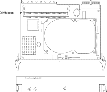
The SPE 200 ships with 512 MB of RAM, provided by two 256 MB dual in-line memory modules (DIMMs), as shown in Figure 1. No memory upgrades are possible on the SPE 200—512 MB is the maximum amount of memory that the SPE 200 supports.
Table 1 provides information about the replacement DIMM for the SPE 200:
| Description | Cisco Part Number |
|---|---|
256-MB SDRAM DIMM | MEM-SPE-256D= |
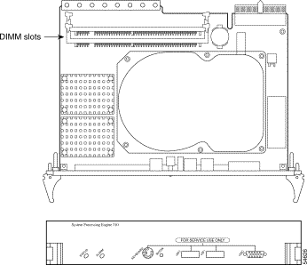
The SPE 310 ships with 512 MB of onboard RAM. You can increase the RAM on the SPE 310 by installing DIMMs in its two DIMM slots (see Figure 2). The maximum amount of RAM that is supported on the SPE 310 is 1.536 GB (with a 512 MB DIMM installed in both slots).
Table 2 provides information about upgrade and replacement DIMMs for the SPE 310:
| Description | Cisco Part Number |
|---|---|
256-MB SDRAM DIMM | MEM-SPE-256D= |
512-MB SDRAM DIMM | MEM-SPE-512D= |
ASI cards ship with 64 MB of onboard RAM. You can install the following types of modules in an ASI card:
Table 3 provides information about the modules that are recommended for installation in ASI cards:
| Description | Cisco Part Number |
|---|---|
16-MB SDRAM DIMM | MEM-MRP-16D= |
32-MB SDRAM DIMM | MEM-MRP-32D= |
16-channel packet voice/fax data DSP module | PVDM-256K-16= |
The MRP 200 ships with 64 MB of onboard RAM. You can install the following types of modules in an MRP 200:
Table 4 provides information about the modules that you can install in the MRP 200:
| Description | Cisco Part Number |
|---|---|
16-MB SDRAM DIMM | MEM-MRP-16D= |
32-MB SDRAM DIMM | MEM-MRP-32D= |
4-channel packet voice/fax data DSP module | PVDM-256K-4= |
8-channel packet voice/fax data DSP module | PVDM-256K-8= |
12-channel packet voice/fax data DSP module | PVDM-256K-12= |
16-channel packet voice/fax data DSP module | PVDM-256K-16= |
20-channel packet voice/fax data DSP module | PVDM-256K-20= |
Virtual private network module | MOD1700-VPN= |
You can hot swap cards while the Cisco ICS 7750 is operating. With hot swapping, you do not need to power down the system.
|
Warning Only trained and qualified personnel should be allowed to install or replace this equipment. |
|
Caution You can install only one SAP and one SSP card in a single Cisco ICS 7750 chassis. If you must hot swap the SAP, the cooling fans do not operate, and the system's ability to detect alarms associated with the operating environment, fans, and power supply modules is degraded until an operational SAP is properly re-inserted in the chassis. If you must hot swap the SSP, the system loses LAN connectivity, and calls being made from or to Cisco IP Phones that are routed through that SSP are disconnected until an operational SSP is properly re-inserted in the chassis. |
|
Note Depending on your system configuration, hot swapping SPEs, ASIs or MRPs can adversely affect users connected to the system. For example, if Cisco CallManager is running on only one SPE, hot swapping that SPE disconnects calls to or from the Public Switched Telephone Network (PSTN) and prevents the system from processing further PSTN traffic until an operational SPE is properly re-inserted in the chassis. Similarly, hot swapping an MRP that is in the process of routing voice or WAN traffic prevents that traffic from reaching its destination. Contact your Cisco sales representative for guidelines on installing cards and software on your system for maximum availability and redundancy. |
The following are examples of recommended insertion practices for system cards:
For card removal instructions, refer to Cisco ICS 7750 FRU Installation and Replacement.
This section shows you how to locate the DIMM and PVDM slots on SPE 200, SPE 310, and MRP 200 cards.
The SPE 200 has two DIMM slots (see Figure 1).
The SPE 310 has two DIMM slots (see Figure 2).
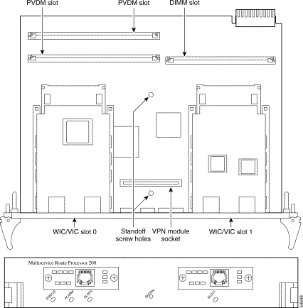
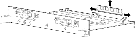
The MRP 200 has one DIMM slot, two PVDM slots, and one VPN module socket. ASI cards have one DIMM slot and two PVDM slots. (see Figure 3).
|
Note For a front view of ASI 81 and ASI 160 cards, refer to the "Processor Cards" chapter in the Cisco ICS 7750 System Description . |
This section explains how to remove and install modules.
|
Warning When performing the procedures in this section, wear grounding wrist straps to avoid ESD damage to the Cisco ICS 7750. Do not directly touch the backplane with your hand or any metal tool, to prevent personal injury or equipment damage. |
This section explains how to remove and install DIMMs.
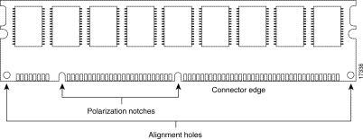
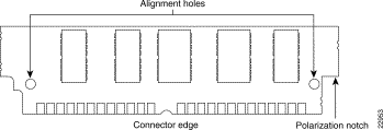
DIMMs are manufactured with polarization notches to ensure proper orientation and with alignment holes to ensure proper positioning. Figure 4 shows the notches and holes on a DIMM. DIMMs are installed with the connector edge down.
|
Caution To avoid damaging ESD-sensitive components, observe all ESD precautions. To avoid damaging the underlying board, do not use excessive force when you remove or replace DIMMs. |
Complete the following steps to remove a DIMM from an SPE:
|
Note In Figure 6, an SPE 200 is shown—use the same procedure for SPE 310 cards. |
Step 2 Locate the DIMM slots on the SPE. See Figure 1.
|
Caution Handle DIMMs by the edges only. DIMMs are ESD-sensitive components and can be damaged by mishandling. |
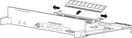
Step 3 Remove the DIMM by pushing the plastic release latches on each side of the DIMM slot outward. (See Figure 5.) This ejects the DIMM from its socket.
Step 4 Hold the DIMM by the edges with your thumbs and index fingers, and lift it out of the socket. Place the removed DIMM in an antistatic bag to protect it from ESD damage.
Step 5 If necessary, repeat Step 3 and Step 4 for the other DIMM.
Complete the following steps to install a DIMM in an SPE:
|
Note In Figure 6, an SPE 200 is shown—use the same procedure for SPE 310 cards. |
|
Caution Handle DIMMs by the edges only. DIMMs are ESD-sensitive components and can be damaged by mishandling. |
Step 2 Remove the DIMM from its antistatic packaging.
Step 3 Hold the DIMM with the polarization notches closer to the card edge and with the connector edge at the bottom.
|
Caution It is normal to feel some resistance when installing a DIMM, but do not use excessive force on the DIMM, and do not touch the surface components. |
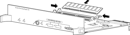
Step 4 Insert the DIMM perpendicular to the socket. Push the DIMM firmly into place (see Figure 6), using the minimum amount of force required. When the DIMM is properly seated, the socket guide posts fit through the alignment holes, and the locking spring clips click into place.
Step 5 Ensure that each DIMM is straight (perpendicular to the socket).
Step 6 If necessary, repeat Steps 3 through 5 for the other DIMM.
|
Note If you do not intend to install components on any other cards, go to "Installing Cards". To install a DIMM on an MRP 200 card or an ASI card, continue. To install PVDMs on an MRP 200 card or an ASI card, go to "Removing and Installing PVDMs". To install a VPN module on an MRP 200, go to "Installing a VPN Module in the MRP 200". |
Complete the following steps to remove the DIMM from an MRP 200 card or an ASI card:
Step 2 Locate the DIMM slot on the MRP 200 card or the ASI card. (See Figure 3.)
|
Caution Handle DIMMs by the edges only. DIMMs are ESD-sensitive components and can be damaged by mishandling. |
Step 3 Remove the DIMM by pushing the plastic release latches on each side of the DIMM slot outward. (See Figure 7.) This ejects the DIMM from its socket.
Step 4 Hold the DIMM by the edges with your thumbs and index fingers, and lift it out of the socket. Place the removed DIMM in an antistatic bag to protect it from ESD damage.
Complete the following steps to install a DIMM in an MRP 200 card or an ASI card:
|
Caution Handle DIMMs by the edges only. DIMMs are ESD-sensitive components and can be damaged by mishandling. |
Step 2 Remove the replacement DIMM from its antistatic packaging.
Step 3 Hold the DIMM with the polarization notches closer to the center of the card and with the connector edge at the bottom.
|
Caution It is normal to feel some resistance when installing a DIMM, but do not use excessive force on the DIMM, and do not touch the surface components. |
Step 4 Insert the DIMM perpendicular to the socket. Push the DIMM firmly into place (see Figure 8), using the minimum amount of force required. When the DIMM is properly seated, the socket guide posts fit through the alignment holes, and the locking spring clips click into place.

Step 5 Ensure that the DIMM is straight (perpendicular to the socket).
|
Note When you finish installing DIMMs, if you do not intend to install PVDMs or a VPN module on this card and do not intend to install components on any other cards, go to "Installing Cards". To install PVDMs on an MRP 200 card or an ASI card, continue with "Removing and Installing PVDMs" on page 19. To install a VPN module on an MRP 200, go to "Installing a VPN Module in the MRP 200". To install DIMMs on an SPE, go to "Installing a DIMM in an SPE Card" on page 16. |
This section explains how to remove and install PVDMs on MRP 200 cards and ASI cards.
PVDMs are manufactured with a polarization notch to ensure proper orientation and with alignment holes to ensure proper positioning. Figure 9 shows the notch and the holes on a PVDM. PVDMs are installed connector-edge down.
|
Caution To avoid damaging ESD-sensitive components, observe all ESD precautions. To avoid damaging MRP 200 or ASI cards, avoid using excessive force when you remove or replace PVDMs. |
Complete the following steps to remove PVDMs:
Step 2 Locate the PVDM slots on the MRP 200 card or the ASI card (see Figure 3).
|
Caution Handle PVDMs by the card edges only. PVDMs are ESD-sensitive components and can be damaged by mishandling. |
Step 3 Remove one PVDM at a time, beginning with the PVDM closest to the rear of the card. To lift the PVDM out of its socket, pull the locking spring clips on both sides outward, and tilt the PVDM toward the rear of the card, free of the clips. (See Figure 10.)
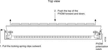
Step 4 Hold the PVDM by the edges with your thumbs and index fingers, and lift it out of the socket. Place the removed PVDM in an antistatic bag to protect it from ESD damage.
Step 5 Repeat Step 4 for the second PVDM.
Complete the following steps to install PVDMs:
Step 2 Locate the PVDM slots on the MRP 200 card or the ASI card (see Figure 3).
|
Caution Handle PVDMs by the card edges only. PVDMs are ESD-sensitive components and can be damaged by mishandling. |
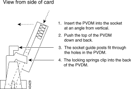
Step 3 Hold the PVDM with the polarization notch closer to the card edge and the connector edge at the bottom (see Figure 10).
Step 4 Beginning with the slot closer to the front of the card, insert the PVDM into the connector slot at an angle, tilted toward the rear of the card. Align or move the PVDM into a vertical position (see Figure 11), using the minimum amount of force required. When the PVDM is properly seated, the socket guide posts fit through the alignment holes, and the connector springs click into place.
Step 5 Ensure that the PVDM is straight and that the alignment holes line up with the plastic guides on the socket (see Figure 10).
|
Caution It is normal to feel some resistance, but do not use excessive force on the PVDM, and do not touch the surface components. |
Step 6 Repeat Step 3 through Step 5 for the second PVDM.
This section explains how to install a VPN module in the MRP 200.
Step 2 Locate the VPN module socket and two holes in the MRP 200 motherboard used for the VPN module standoff screws (see Figure 3).
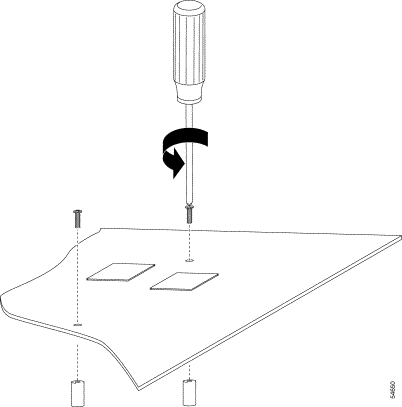
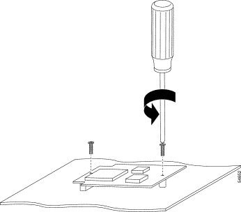
Step 3 Turn the MRP over and attach the two metal standoffs to the MRP 200 using the screws provided with the VPN module (see Figure 12). The standoffs should be on the same side of the motherboard as the VPN module socket.
|
Caution Handle the MRP 200 and the VPN module by the card edges only. These items are ESD-sensitive components and can be damaged by mishandling. |
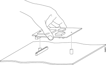
Step 4 Turn the MRP back over and insert the VPN module into the VPN module socket (see Figure 13).
Step 5 Secure the VPN module to the metal standoffs (see Figure 14).
For card installation instructions, refer to Cisco ICS 7750 FRU Installation and Replacement.
Under the terms and conditions of the Cisco Systems return materials authorization (RMA) policy, any replaced RMA parts must be returned to Cisco Systems.
Follow these guidelines to return parts:
To check the status of your RMA on the web, go to: http://www.cisco.com/cgi-bin/agents/status.pl.
If you have any questions, please use any of the following methods to contact Cisco Systems:
The following sections provide sources for obtaining documentation from Cisco Systems.
You can access the most current Cisco documentation on the World Wide Web at the following sites:
Cisco documentation and additional literature are available in a CD-ROM package, which ships with your product. The Documentation CD-ROM is updated monthly and may be more current than printed documentation. The CD-ROM package is available as a single unit or as an annual subscription.
Cisco documentation is available in the following ways:
If you are reading Cisco product documentation on the World Wide Web, you can submit technical comments electronically. Click Feedback in the toolbar and select Documentation. After you complete the form, click Submit to send it to Cisco.
You can e-mail your comments to bug-doc@cisco.com.
To submit your comments by mail, for your convenience many documents contain a response card behind the front cover. Otherwise, you can mail your comments to the following address:
Cisco Systems, Inc.
Document Resource Connection
170 West Tasman Drive
San Jose, CA 95134-9883
We appreciate your comments.
Cisco provides Cisco.com as a starting point for all technical assistance. Customers and partners can obtain documentation, troubleshooting tips, and sample configurations from online tools. For Cisco.com registered users, additional troubleshooting tools are available from the TAC website.
Cisco.com is the foundation of a suite of interactive, networked services that provides immediate, open access to Cisco information and resources at anytime, from anywhere in the world. This highly integrated Internet application is a powerful, easy-to-use tool for doing business with Cisco.
Cisco.com provides a broad range of features and services to help customers and partners streamline business processes and improve productivity. Through Cisco.com, you can find information about Cisco and our networking solutions, services, and programs. In addition, you can resolve technical issues with online technical support, download and test software packages, and order Cisco learning materials and merchandise. Valuable online skill assessment, training, and certification programs are also available.
Customers and partners can self-register on Cisco.com to obtain additional personalized information and services. Registered users can order products, check on the status of an order, access technical support, and view benefits specific to their relationships with Cisco.
To access Cisco.com, go to the following website:
The Cisco TAC website is available to all customers who need technical assistance with a Cisco product or technology that is under warranty or covered by a maintenance contract.
If you have a priority level 3 (P3) or priority level 4 (P4) problem, contact TAC by going to the TAC website:
P3 and P4 level problems are defined as follows:
In each of the above cases, use the Cisco TAC website to quickly find answers to your questions.
To register for Cisco.com, go to the following website:
http://www.cisco.com/register/
If you cannot resolve your technical issue by using the TAC online resources, Cisco.com registered users can open a case online by using the TAC Case Open tool at the following website:
http://www.cisco.com/tac/caseopen
If you have a priority level 1 (P1) or priority level 2 (P2) problem, contact TAC by telephone and immediately open a case. To obtain a directory of toll-free numbers for your country, go to the following website:
http://www.cisco.com/warp/public/687/Directory/DirTAC.shtm l
P1 and P2 level problems are defined as follows:
This document is to be used in conjunction with the Cisco ICS 7750 Hardware Installation Guide publication.
AccessPath, AtmDirector, Browse with Me, CCIP, CCSI, CD-PAC, CiscoLink, the Cisco Powered Network logo, Cisco Systems Networking Academy, the Cisco Systems Networking Academy logo, Fast Step, Follow Me Browsing, FormShare, FrameShare, GigaStack, IGX, Internet Quotient, IP/VC, iQ Breakthrough, iQ Expertise, iQ FastTrack, the iQ Logo, iQ Net Readiness Scorecard, MGX, the Networkers logo, Packet, RateMUX, ScriptBuilder, ScriptShare, SlideCast, SMARTnet, TransPath, Unity, Voice LAN, Wavelength Router, and WebViewer are trademarks of Cisco Systems, Inc.; Changing the Way We Work, Live, Play, and Learn, Discover All That's Possible, and Empowering the Internet Generation, are service marks of Cisco Systems, Inc.; and Aironet, ASIST, BPX, Catalyst, CCDA, CCDP, CCIE, CCNA, CCNP, Cisco, the Cisco Certified Internetwork Expert logo, Cisco IOS, the Cisco IOS logo, Cisco Systems, Cisco Systems Capital, the Cisco Systems logo, Enterprise/Solver, EtherChannel, EtherSwitch, FastHub, FastSwitch, IOS, IP/TV, LightStream, MICA, Network Registrar, PIX, Post-Routing, Pre-Routing, Registrar, StrataView Plus, Stratm, SwitchProbe, TeleRouter, and VCO are registered trademarks of Cisco Systems, Inc. and/or its affiliates in the U.S. and certain other countries.
All other trademarks mentioned in this document or Web site are the property of their respective owners. The use of the word partner does not imply a partnership relationship between Cisco and any other company. (0106R)
Installing Memory, PVDM, and VPN Modules in ASI Cards, MRP Cards, and SPE Cards in the Cisco ICS 7750
Copyright © 2000-2001, Cisco Systems, Inc.
All rights reserved.
![]()
![]()
![]()
![]()
![]()
![]()
![]()
![]()
Posted: Sun Dec 16 23:14:18 PST 2001
All contents are Copyright © 1992--2001 Cisco Systems, Inc. All rights reserved.
Important Notices and Privacy Statement.