|
|

Table Of Contents
Installing the Phone and Connecting to the Network
Installing the Cisco IP Phone
Before you can successfully install the Cisco IP phone, your system administrator must prepare the network for your phone. If a technician is not installing your phone, verify with the system administrator that the network is ready for your phone, read the safety notices, and install your phone.
The following sections provide information to help you install your Cisco IP Phone 7940/7960:
•
Installing the Phone and Connecting to the Network
Safety Notices
These are the safety considerations for using the Cisco IP Phone. Read these notices before installing or using your phone. Translations of the following warnings are available in "Translated Safety Warnings." Additionally, the Cisco IP Phone 7900 Family Administration Guide includes regulatory compliance information about your phone, which your system administrator can review.
Warning
Warning
Warning
Warning
Warning
The next warning applies when you use an external power supply.
Warning
Warning
Caution
Installing the Phone and Connecting to the Network
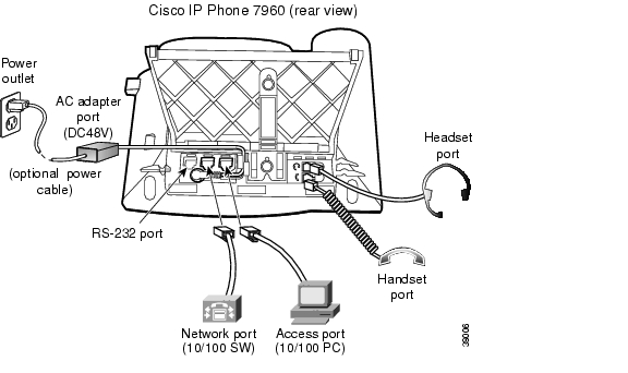
Read the information in the "Safety Notices" section before installing your phone. Refer to Figure 2-1 for an overview about how to connect the Cisco IP Phone 7940/7960 to your personal computer (PC), network, power, and headset. All phone connection ports are located at the rear of the phone base unit.
Use the following procedure to install the phone on a network that has already been prepared to host the phone.
Step 1
Use the Ethernet cable supplied in the box with your IP phone. If you need a longer Ethernet cable, contact your system administrator.
Step 2
See the "Using the Headset" section on page 3-2 for a list of supported headsets.
Note
Step 3
You can connect your computer to the phone to enable your PC to access the network through the IP phone. You might choose this option if you do not have multiple Ethernet ports in your workspace.
Step 4
The Cisco IP Phone 7940/7960 can be powered by an external power source, a switching module, or a power patch panel. If you are not sure how your phone is receiving power, ask your system administrator.
Step 5
a.
b.
c.
You can also mount the Cisco IP Phone 7960 on a wall. Contact your system administrator if you want to do this.
Figure 2-1 Cisco IP Phone 7940/7960 Cable Connections
After theCisco IP Phone 7940/7960 has power connected to it, the phone begins its startup process. Once the setup process is completed, the main LCD screen appears, displaying the phone extension (or directory number), softkeys, and the current time and date. If the phone does not successfully start up, contact your system administrator for help.
![]()
![]()
![]()
![]()
![]()
![]()
![]()
![]()
Posted: Mon Feb 7 13:43:43 PST 2005
All contents are Copyright © 1992--2005 Cisco Systems, Inc. All rights reserved.
Important Notices and Privacy Statement.