Table Of Contents
SIP Call Flows
Call Flow Scenarios for Successful Calls
Gateway to Cisco SIP IP Phone in a SIP Network
Cisco SIP IP Phone to Cisco SIP IP Phone
Call Flow Scenarios for Failed Calls
Gateway to Cisco SIP IP Phone in a SIP Network
Cisco SIP IP Phone to Cisco SIP IP Phone in a SIP Network
SIP Call Flows
This appendix includes the following sections:
• Call Flow Scenarios for Successful Calls
• Call Flow Scenarios for Failed Calls
SIP uses the following request methods:
•INVITE—Indicates that a user or service is being invited to participate in a call session.
•ACK—Confirms that the client has received a final response to an INVITE request.
•BYE—Terminates a call and can be sent by either the caller or the called party.
•CANCEL—Cancels any pending searches but does not terminate a call that has already been accepted.
•OPTIONS—Queries the capabilities of servers.
•REGISTER—Registers the address listed in the To header field with a SIP server.
•REFER—Indicates that the user (recipient) should contact a third party for use in transferring parties.
•NOTIFY—Notifies the user of the status of a transfer using REFER. Also used for remote reboot and message waiting indication (MWI).
The following types of responses are used by SIP and generated by the Cisco SIP gateway:
•SIP 1xx—Informational Responses
•SIP 2xx—Successful Responses
•SIP 3xx—Redirection Responses
•SIP 4xx—Client Failure Responses
•SIP 5xx—Server Failure Responses
•SIP 6xx—Global Failure Responses
Note If you have enabled the rfc_2543_hold parameter, the phone will use the RFC 2543 method for putting a call on hold, and will set the media address to 0.0.0.0. The examples in this chapter assume that this parameter is not enabled, and show the phone using the RFC 3264 method.
For example, if the rfc_2543_hold parameter is enabled, the INVITE request in step 5 in the "Simple Call Hold" section would be sent as INVITE (c=IN IP4 0.0.0.0 a=inactive).
Call Flow Scenarios for Successful Calls
This section describes successful call flow scenarios, which are as follows:
• Gateway to Cisco SIP IP Phone in a SIP Network
• Cisco SIP IP Phone to Cisco SIP IP Phone
Gateway to Cisco SIP IP Phone in a SIP Network
The following scenarios describe and illustrate successful calls in a gateway to a Cisco SIP IP phone:
• Call Setup and Disconnect
• Call Setup and Hold
• Call to a Gateway Acting As an Emergency Proxy from a Cisco SIP IP Phone
Call Setup and Disconnect
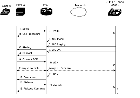
Figure B-1 illustrates a successful phone-call setup and disconnect. In this scenario, the two end users are User A and User B. User A is located at PBX A. PBX A is connected to Gateway 1 (SIP gateway) via a T1/E1. User B is located at a Cisco SIP IP phone. Gateway 1 is connected to the Cisco SIP IP phone over an IP network.
The call flow is as follows:
1. User A calls User B.
2. User B answers the call.
3. User B hangs up.
Figure B-1 Successful Setup and Disconnect
Step
|
Action
|
Description
|
1.
|
Setup—PBX A to Gateway 1
|
Call setup is initiated between PBX A and Gateway 1. Setup includes the standard transactions that take place as User A attempts to call User B.
|
2.
|
INVITE—Gateway 1 to Cisco SIP IP phone
|
Gateway 1 maps the SIP URL phone number to a dial peer. The dial peer includes the IP address and the port number of the SIP-enabled entity to contact. Gateway 1 sends a SIP INVITE request to the address it receives as the dial peer, which, in this scenario, is the IP phone. In the INVITE request:
•The IP address of the phone is inserted in the Request-URI field.
•PBX A is identified as the call session initiator in the From field.
•A unique numeric identifier is assigned to the call and is inserted in the Call-ID field.
•The transaction number within a single call leg is identified in the CSeq field.
•The media capability that User A is ready to receive is specified.
•The port on which the gateway is prepared to receive the RTP data is specified.
|
3.
|
Call Proceeding—Gateway 1 to PBX A
|
Gateway 1 sends a Call Proceeding message to PBX A to acknowledge the Call Setup request.
|
4.
|
100 Trying—Cisco SIP IP phone to Gateway 1
|
The phone sends a SIP 100 Trying response to Gateway 1. The response indicates that the INVITE request has been received.
|
5.
|
180 Ringing—Cisco SIP IP phone to Gateway 1
|
The phone sends a SIP 180 Ringing response to Gateway 1. The response indicates that the user is being alerted.
|
6.
|
Alerting—Gateway 1 to PBX A
|
Gateway 1 sends an Alert message to User A. The message indicates that Gateway 1 has received a 180 Ringing response from the phone. User A hears the ringback tone that indicates that User B is being alerted.
|
7.
|
200 OK—Cisco SIP IP phone to Gateway 1
|
The phone sends a SIP 200 OK response to Gateway 1. The response notifies Gateway 1 that the connection has been made.
|
8.
|
Connect—Gateway 1 to PBX A
|
Gateway 1 sends a Connect message to the PBX A. The message notifies PBX A that the connection has been made.
|
9.
|
Connect ACK—PBX A to Gateway 1
|
PBX A acknowledges Gateway 1's Connect message.
|
10.
|
ACK—Gateway 1 to Cisco SIP IP phone
|
Gateway 1 sends a SIP ACK to the phone. The ACK confirms that Gateway 1 has received the 200 OK response. The call session is now active.
|
11.
|
BYE—Cisco SIP IP phone to Gateway 1
|
User B terminates the call session. The phone sends a SIP BYE request to Gateway 1. The request indicates that User B wants to release the call.
|
12.
|
Disconnect—Gateway 1 to PBX A
|
Gateway 1 sends a Disconnect message to PBX A.
|
13.
|
Release—PBX A to Gateway 1
|
PBX A sends a Release message to Gateway 1.
|
14.
|
200 OK—Gateway 1 to Cisco SIP IP phone
|
Gateway 1 sends a SIP 200 OK response to the phone. The response notifies the phone that Gateway 1 has received the BYE request.
|
15.
|
Release Complete—Gateway 1 to PBX A
|
Gateway 1 sends a Release Complete message to PBX A, and the call session terminates.
|
Call Setup and Hold
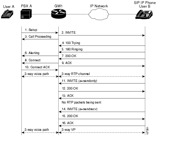
Figure B-2 illustrates a successful phone-call setup and call hold. In this scenario, the two end users are User A and User B. User A is located at PBX A. PBX A is connected to Gateway 1 (SIP gateway) via a T1/E1. User B is located at a Cisco SIP IP phone. Gateway 1 is connected to the Cisco SIP IP phone over an IP network.
The call flow is as follows:
1. User A calls User B.
2. User B answers the call.
3. User B puts User A on hold.
4. User B takes User A off hold.
Figure B-2 Successful Call Setup and Hold
Step
|
Action
|
Description
|
1.
|
Setup—PBX A to Gateway 1
|
Call setup is initiated between PBX A and Gateway 1. Setup includes the standard transactions that take place as User A attempts to call User B.
|
2.
|
INVITE—Gateway 1 to Cisco SIP IP phone
|
Gateway 1 maps the SIP URL phone number to a dial peer. The dial peer includes the IP address and the port number of the SIP-enabled entity to contact. Gateway 1 sends a SIP INVITE request to the address it receives as the dial peer, which, in this scenario, is the IP phone. In the INVITE request:
•The IP address of the phone is inserted in the Request-URI field.
•PBX A is identified as the call session initiator in the From field.
•A unique numeric identifier is assigned to the call and is inserted in the Call-ID field.
•The transaction number within a single call leg is identified in the CSeq field.
•The media capability that User A is ready to receive is specified.
•The port on which the gateway is prepared to receive the RTP data is specified.
|
3.
|
Call Proceeding—Gateway 1 to PBX A
|
Gateway 1 sends a Call Proceeding message to the PBX A to acknowledge the Call Setup request.
|
4.
|
100 Trying—Cisco IP Phone 7960G/7940G to Gateway 1
|
The phone sends a SIP 100 Trying response to Gateway 1. The response indicates that the INVITE request has been received.
|
5.
|
180 Ringing—Cisco SIP IP hone to Gateway 1
|
The phone sends a SIP 180 Ringing response to Gateway 1. The response indicates that the user is being alerted.
|
6.
|
Alerting—Gateway 1 to the PBX A
|
Gateway 1 sends an Alert message to User A. The message indicates that Gateway 1 has received a 180 Ringing response from the phone. User A hears the ringback tone that indicates that User B is being alerted.
|
7.
|
200 OK—Cisco SIP IP phone to Gateway 1
|
The phone sends a SIP 200 OK response to Gateway 1. The response notifies Gateway 1 that the connection has been made.
|
8.
|
Connect—Gateway 1 to PBX A
|
Gateway 1 sends a Connect message to PBX A. The message notifies PBX A that the connection has been made.
|
9.
|
ACK—Gateway 1 to Cisco SIP IP phone
|
Gateway 1 sends a SIP ACK to the phone. The ACK confirms that User A has received the 200 OK response. The call session is now active.
|
10.
|
Connect ACK—PBX A to Gateway 1
|
PBX A acknowledges Gateway 1's Connect message.
|
11.
|
INVITE—Cisco SIP IP phone to Gateway 1
|
Phone B sends a midcall INVITE to Gateway1 with new Session Description Protocol (SDP) attribute parameter.
SDP: a=sendonly
The a= SDP field of the SIP INVITE contains sendonly. This value places the call on hold.
|
12.
|
200 OK—Gateway 1 to Cisco SIP IP phone
|
Gateway 1 sends a SIP 200 OK response to the phone. The response notifies the phone that the INVITE was successfully processed.
|
13.
|
ACK—Cisco SIP IP phone to Gateway 1
|
The phone sends a SIP ACK to Gateway 1. The ACK confirms that the phone has received the 200 OK response. The call session is now temporarily inactive. No RTP packets are being sent.
|
14.
|
INVITE—Cisco SIP IP phone to Gateway 1
|
User B takes User A off hold. Phone B sends a SIP INVITE request to Phone A with the same call ID as the previous INVITE and a new SDP attribute parameter (sendrecv), which is used to reestablish the call.
|
15.
|
200 OK—Gateway 1 to Cisco SIP IP phone
|
Gateway 1 sends a SIP 200 OK response to the phone. The response notifies the phone that the INVITE was successfully processed.
|
16.
|
ACK—Cisco SIP IP phone to Gateway 1
|
The phone sends a SIP ACK to Gateway 1. The ACK confirms that the phone has received the 200 OK response. The call session is now active.
|
Call to a Gateway Acting As an Emergency Proxy from a Cisco SIP IP Phone
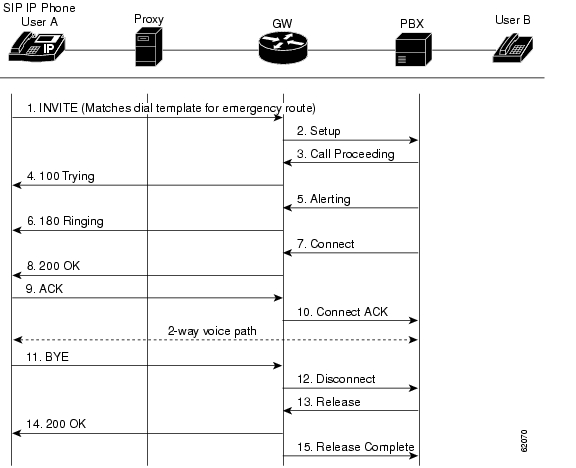
Figure B-3 illustrates a successful call from a Cisco SIP IP phone to a gateway acting as an emergency proxy.
Figure B-3 Successful Call from Cisco SIP IP Phone to SIP Gateway (Emergency Proxy)
Step
|
Action
|
Description
|
1.
|
INVITE—Cisco SIP IP phone to the gateway (emergency proxy)
|
The phone tries to connect to the gateway (emergency proxy) by sending out the INVITE message. The dial template for the emergency route is matched.
|
2.
|
Setup—Gateway to the PBX
|
Call setup is initiated between the gateway and the PBX. Setup includes the standard transactions that take place as User A attempts to call User B.
|
3.
|
Call Proceeding—PBX to the gateway
|
The PBX sends a Call Proceeding message to the gateway to acknowledge the Call Setup request.
|
4.
|
100 Trying—Gateway to Cisco SIP IP phone (User A)
|
The gateway sends a SIP 100 Trying response to User A. The response indicates that the INVITE request has been received.
|
5.
|
Alerting—PBX to the gateway
|
The PBX sends an Alert message to the gateway. The message indicates that the PBX has received a 100 Trying Ringing response from the gateway.
|
6.
|
180 Ringing—Gateway to Cisco SIP IP phone (User A)
|
The gateway sends a SIP 180 Ringing response to User A. The response indicates that the gateway is being alerted.
|
7.
|
Connect—PBX to the gateway
|
The PBX sends a Connect message to the gateway. The message notifies the gateway that the connection has been made.
|
8.
|
200 OK—Gateway to Cisco SIP IP phone (User A)
|
The gateway sends a SIP 200 OK response to User A. The response notifies User A that the connection has been made.
|
9.
|
ACK—Cisco SIP IP phone (User A) to the gateway
|
User A sends a SIP ACK to the gateway. The ACK confirms that User A has received the 200 OK response. The call session is now active.
|
10.
|
Connect ACK—Gateway to the PBX
|
The gateway acknowledges PBX's Connect message.
|
11.
|
BYE—Cisco SIP IP phone (User A) to the gateway
|
User A terminates the call session and sends a SIP BYE request to the gateway. The request indicates that User A wants to release the call.
|
12.
|
Disconnect—Gateway to the PBX
|
The gateway sends a Disconnect message to the PBX.
|
13.
|
Release—PBX to the gateway
|
The PBX sends a Release message to the gateway.
|
14.
|
200 OK—Gateway to Cisco SIP IP phone (User A)
|
The gateway sends a SIP 200 OK response to User A. The response notifies User A that the gateway has received the BYE request.
|
15.
|
Release Complete—Gateway to the PBX
|
The gateway sends a Release Complete message to the PBX and the call session terminates.
|
Cisco SIP IP Phone to Cisco SIP IP Phone
The following sections describe and illustrate successful calls from a Cisco SIP IP phone to another Cisco SIP IP phone:
• Simple Call Hold
• Call Hold with Consultation
• Call Waiting
• Call Transfer Without Consultation
• Call Transfer Without Consultation Using Failover
• Call Transfer with Consultation
• Call Transfer with Consultation Using Failover
• Network Call Forwarding (Unconditional)
• Network Call Forwarding (Busy)
• Network Call Forwarding (No Answer)
• Three-Way Calling
• Call from a Cisco SIP IP Phone to a Gateway Acting As a Backup Proxy in a SIP Network
• Call from a Cisco SIP IP Phone to a Cisco SIP IP Phone Using a SIP Backup Proxy
• Call from a Cisco SIP IP Phone to a Cisco SIP IP Phone Using a SIP Emergency Proxy
Simple Call Hold
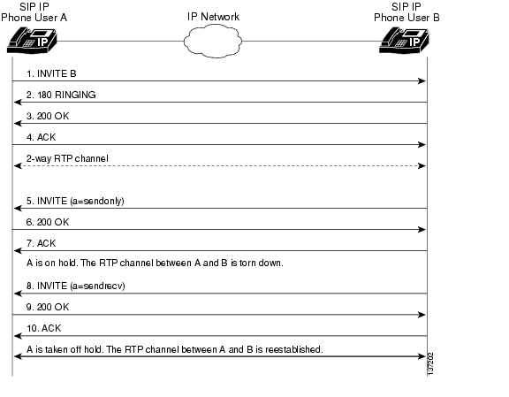
Figure B-4 illustrates a successful call between Cisco SIP IP phones in which one of the participants places the other on hold and then returns to the call. In this call flow scenario, the two end users are User A and User B. User A and User B are both using Cisco SIP IP phones, which are connected via an IP network.
The call flow scenario is as follows:
1. User A calls User B.
2. User B answers the call.
3. User B places User A on hold.
4. User B takes User A off hold.
5. The call continues.
Figure B-4 Simple Call Hold
Step
|
Action
|
Description
|
1.
|
INVITE—Phone A to Phone B
|
Phone A sends a SIP INVITE request to Phone B. The request is an invitation to User B to participate in a call session. In the INVITE request:
•The phone number of User B is inserted in the Request-URI field in the form of a SIP URL. The SIP URL identifies the address of User B and takes a form similar to an e-mail address (user@host, where user is the telephone number and host is either a domain name or a numeric network address). For example, the Request-URI field in the INVITE request to User B appears as "INVITE sip:555-0199@companyb.com; user=phone." The "user=phone" parameter distinquishes that the Request-URI address is a telephone number rather than a username.
•Phone A is identified as the call session initiator in the From field.
•A unique numeric identifier is assigned to the call and is inserted in the Call-ID field.
•The transaction number within a single call leg is identified in the CSeq field.
•The media capability User A is ready to receive is specified.
|
2.
|
180 Ringing—Phone B to Phone A
|
Phone B sends a SIP 180 Ringing response to Phone A.
|
3.
|
200 OK—Phone B to Phone A
|
Phone B sends a SIP 200 OK response to Phone A. The response notifies Phone A that the connection has been made.
If Phone B supports the media capability advertised in the INVITE message sent by Phone A, it advertises the intersection of its own and Phone A's media capability in the 200 OK response. If Phone B does not support the media capability advertised by Phone A, it sends back a 400 Bad Request response with a 304 Warning header field.
|
4.
|
ACK—Phone A to Phone B
|
Phone A sends a SIP ACK to Phone B. The ACK confirms that Phone A has received the 200 OK response from Phone B.
The ACK might contain a message body with the final session description to be used by Phone B. If the message body of the ACK is empty, Phone B uses the session description in the INVITE request.
|
A two-way RTP channel is established between Phone A and Phone B.
|
5.
|
INVITE—Phone B to Phone A
|
Phone B sends a midcall INVITE to Phone A with new Session Description Protocol (SDP) attribute parameter.
SDP: a=sendonly
The a= SDP field of the SIP INVITE contains sendonly. This value places the call on hold.
|
6.
|
200 OK—Phone A to Phone B
|
Phone A sends a SIP 200 OK response to Phone B.
|
7.
|
ACK—Phone B to Phone A
|
Phone B sends a SIP ACK to Phone A. The ACK confirms that Phone B has received the 200 OK response from Phone A.
|
The RTP channel between Phone A and Phone B is torn down.
|
8.
|
INVITE—Phone B to Phone A
|
User B takes User A off hold. Phone B sends a SIP INVITE request to Phone A with the same call ID as the previous INVITE and a new SDP attribute parameter (sendrecv), which is used to reestablish the call.
|
9.
|
200 OK—Phone A to Phone B
|
Phone A sends a SIP 200 OK response to Phone B.
|
10.
|
ACK—Phone B to Phone A
|
Phone B sends a SIP ACK to Phone A. The ACK confirms that Phone B has received the 200 OK response from Phone A.
|
A two-way RTP channel is reestablished between Phone A and Phone B.
|
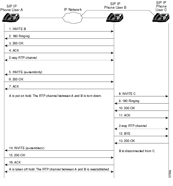
Call Hold with Consultation
Figure B-5 illustrates a successful call between Cisco SIP IP phones in which one of the participants places the other on hold, calls a third party (consultation), and then returns to the original call. In this call flow scenario, the end users are User A, User B, and User C. They are all using Cisco SIP IP phones, which are connected via an IP network.
The call flow scenario is as follows:
1. User A calls User B.
2. User B answers the call.
3. User B places User A on hold.
4. User B calls User C.
5. User B disconnects from User C.
6. User B takes User A off hold.
7. The original call continues.
Figure B-5 Call Hold with Consultation
Step
|
Action
|
Description
|
1.
|
INVITE—Phone A to Phone B
|
Phone A sends a SIP INVITE request to Phone B. The request is an invitation to User B to participate in a call session. In the INVITE request:
•The phone number of User B is inserted in the Request-URI field in the form of a SIP URL. The SIP URL identifies the address of User B and takes a form similar to an e-mail address (user@host, where user is the telephone number and host is either a domain name or a numeric network address). For example, the Request-URI field in the INVITE request to User B appears as "INVITE sip:555-0199@companyb.com; user=phone." The "user=phone" parameter distinquishes that the Request-URI address is a telephone number rather than a username.
•Phone A is identified as the call session initiator in the From field.
•A unique numeric identifier is assigned to the call and is inserted in the Call-ID field.
•The transaction number within a single call leg is identified in the CSeq field.
•The media capability User A is ready to receive is specified.
|
2.
|
180 Ringing—Phone B to Phone A
|
Phone B sends a SIP 180 Ringing response to Phone A.
|
3.
|
200 OK—Phone B to Phone A
|
Phone B sends a SIP 200 OK response to Phone A. The response notifies Phone A that the connection has been made.
If Phone B supports the media capability advertised in the INVITE message sent by Phone A, it advertises the intersection of its own and Phone A's media capability in the 200 OK response. If Phone B does not support the media capability advertised by Phone A, it sends back a 400 Bad Request response with a 304 Warning header field.
|
4.
|
ACK—Phone A to Phone B
|
Phone A sends a SIP ACK to Phone B. The ACK confirms that Phone A has received the 200 OK response from Phone B.
The ACK might contain a message body with the final session description to be used by Phone B. If the message body of the ACK is empty, Phone B uses the session description in the INVITE request.
|
A two-way RTP channel is established between Phone A and Phone B.
|
5.
|
INVITE—Phone B to Phone A
|
Phone B sends a midcall INVITE to Phone A with new Session Description Protocol (SDP) attribute parameter.
SDP: a=sendonly
The a= SDP field of the SIP INVITE contains sendonly. This value places the call on hold.
|
6.
|
200 OK—Phone A to Phone B
|
Phone A sends a SIP 200 OK response to Phone B.
|
7.
|
ACK—Phone B to Phone A
|
Phone B sends a SIP ACK to Phone A. The ACK confirms that Phone B has received the 200 OK response from Phone A.
|
The RTP channel between Phone A and Phone B is torn down.
|
8.
|
INVITE—Phone B to Phone C
|
Phone B sends a SIP INVITE request to Phone C. The request is an invitation to User C to participate in a call session.
|
9.
|
180 Ringing—Phone C to Phone B
|
Phone C sends a SIP 180 Ringing response to Phone B.
|
10.
|
200 OK—Phone C to Phone B
|
Phone C sends a SIP 200 OK response to Phone B. The response notifies Phone B that the connection has been made.
If Phone B supports the media capability advertised in the INVITE message sent by Phone A, it advertises the intersection of its own and Phone A's media capability in the 200 OK response. If Phone B does not support the media capability advertised by Phone A, it sends back a 400 Bad Request response with a 304 Warning header field.
|
11.
|
ACK—Phone B to Phone C
|
Phone B sends a SIP ACK to Phone C. The ACK confirms that Phone B has received the 200 OK response from Phone C.
The ACK might contain a message body with the final session description to be used by Phone C. If the message body of the ACK is empty, Phone C uses the session description in the INVITE request.
|
A two-way RTP channel is established between Phone B and Phone C.
|
12.
|
BYE—Phone B to Phone C
|
The call continues and then User B hangs up. Phone B sends a SIP BYE request to Phone C. The request indicates that User B wants to release the call.
|
13.
|
200 OK—Phone C to Phone B
|
Phone C sends a SIP 200 OK response to Phone B. The response notifies Phone B that the BYE request has been received. The call session between User A and User B terminates.
|
The RTP channel between Phone B and Phone C is torn down.
|
14.
|
INVITE—Phone B to Phone A
|
User B takes User A off hold. Phone B sends a SIP INVITE request to Phone A with the same call ID as the previous INVITE and a new SDP attribute parameter (sendrecv), which is used to reestablish the call.
|
15.
|
200 OK—Phone A to Phone B
|
Phone A sends a SIP 200 OK response to Phone B.
|
16.
|
ACK—Phone B to Phone A
|
Phone B sends a SIP ACK to Phone A. The ACK confirms that Phone B has received the 200 OK response from Phone A.
|
A two-way RTP channel is reestablished between Phone A and Phone B.
|
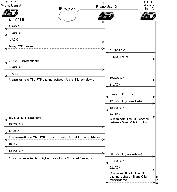
Call Waiting
Figure B-6 illustrates a successful call between Cisco SIP IP phones in which two parties are in a call, and one of the participants receives a call from a third party and then returns to the original call. In this call flow scenario, the end users are User A, User B, and User C. They are all using Cisco IP Phone 7960G/7940G, which are connected using an IP network.
The call flow scenario is as follows:
1. User A calls User B.
2. User B answers the call.
3. User C calls User B.
4. User B accepts the call from User C.
5. User B switches back to User A.
6. User B hangs up, ending the call with User A.
7. User B is notified of the remaining call with User C.
8. User B answers the notification and continues the call with User C.
Figure B-6 Call Waiting
Step
|
Action
|
Description
|
1.
|
INVITE—Phone A to Phone B
|
Phone A sends a SIP INVITE request to Phone B. The request is an invitation to User B to participate in a call session. In the INVITE request:
•The phone number of User B is inserted in the Request-URI field in the form of a SIP URL. The SIP URL identifies the address of User B and takes a form similar to an e-mail address (user@host, where user is the telephone number and host is either a domain name or a numeric network address). For example, the Request-URI field in the INVITE request to User B appears as "INVITE sip:555-0199@companyb.com; user=phone." The "user=phone" parameter distinquishes that the Request-URI address is a telephone number rather than a username.
•Phone A is identified as the call session initiator in the From field.
•A unique numeric identifier is assigned to the call and is inserted in the Call-ID field.
•The transaction number within a single call leg is identified in the CSeq field.
•The media capability User A is ready to receive is specified.
|
2.
|
180 Ringing—Phone B to Phone A
|
Phone B sends a SIP 180 Ringing response to Phone A.
|
3.
|
200 OK—Phone B to Phone A
|
Phone B sends a SIP 200 OK response to Phone A. The response notifies Phone A that the connection has been made.
If Phone B supports the media capability advertised in the INVITE message sent by Phone A, it advertises the intersection of its own and Phone A media capability in the 200 OK response. If Phone B does not support the media capability advertised by Phone A, it sends back a 400 Bad Request response with a 304 Warning header field.
|
4.
|
ACK—Phone A to Phone B
|
Phone A sends a SIP ACK to Phone B. The ACK confirms that Phone A has received the 200 OK response from Phone B.
The ACK might contain a message body with the final session description to be used by Phone B. If the message body of the ACK is empty, Phone B uses the session description in the INVITE request.
|
A two-way RTP channel is established between Phone A and Phone B.
|
5.
|
INVITE—Phone C to Phone B
|
Phone C sends a SIP INVITE request to Phone B. The request is an invitation to User B to participate in a call session.
|
6.
|
180 Ringing—Phone B to Phone C
|
Phone B sends a SIP 180 Ringing response to Phone C.
|
7.
|
INVITE—Phone B to Phone A
|
Phone B sends a midcall INVITE to Phone A with new Session Description Protocol (SDP) attribute parameter.
SDP: a=sendonly
The a= SDP field of the SIP INVITE contains sendonly. This value places the call on hold.
|
8.
|
200 OK—Phone A to Phone B
|
Phone A sends a SIP 200 OK response to Phone B.
|
9.
|
ACK—Phone B to Phone A
|
Phone B sends a SIP ACK to Phone A. The ACK confirms that Phone B has received the 200 OK response from Phone A.
|
The RTP channel between Phone A and Phone B is torn down.
|
10.
|
200 OK—Phone B to Phone C
|
Phone B sends a SIP 200 OK response to Phone C. The response notifies Phone C that the connection has been made.
|
11.
|
ACK—Phone C to Phone B
|
Phone C sends a SIP ACK to Phone B. The ACK confirms that Phone C has received the 200 OK response from Phone B.
The ACK might contain a message body with the final session description to be used by Phone B. If the message body of the ACK is empty, Phone B uses the session description in the INVITE request.
|
A two-way RTP channel is established between Phone B and Phone C.
|
12.
|
INVITE—Phone B to Phone C
|
Phone B sends a midcall INVITE to Phone C with new Session Description Protocol (SDP) attribute parameter.
SDP: a=sendonly
The a= SDP field of the SIP INVITE contains sendonly. This value places the call on hold.
|
13.
|
200 OK—Phone C to Phone B
|
Phone C sends a SIP 200 OK response to Phone B.
|
14.
|
ACK—Phone B to Phone C
|
Phone B sends a SIP ACK to Phone C. The ACK confirms that Phone B has received the 200 OK response from Phone C.
|
The RTP channel between Phone B and Phone C is torn down.
|
15.
|
INVITE—Phone B to Phone A
|
User B takes User A off hold. Phone B sends a SIP INVITE request to Phone A with the same call ID as the previous INVITE and a new SDP attribute parameter (sendrecv), which is used to reestablish the call.
|
16.
|
200 OK—Phone A to Phone B
|
Phone A sends a SIP 200 OK response to Phone B.
|
17.
|
ACK—Phone B to Phone A
|
Phone B sends a SIP ACK to Phone A. The ACK confirms that Phone B has received the 200 OK response from Phone A.
|
A two-way RTP channel is reestablished between Phone A and Phone B.
|
18.
|
BYE—Phone B to Phone A
|
The call continues and then User B hangs up. Phone B sends a SIP BYE request to Phone A. The request indicates that User B wants to release the call.
|
19.
|
200 OK—Phone A to Phone B
|
Phone A sends a SIP 200 OK response to Phone B. The response notifies Phone B that the BYE request has been received. The call session between User A and User B terminates.
|
The RTP channel between Phone A and Phone B is torn down.
|
20.
|
INVITE—Phone B to Phone C
|
User B takes User C off hold. Phone B sends a SIP INVITE request to Phone C with the same call ID as the previous INVITE (sent to Phone C) and a new SDP attribute parameter (sendrecv), which is used to reestablish the call.
|
21.
|
200 OK—Phone C to Phone B
|
Phone C sends a SIP 200 OK response to Phone B.
|
22.
|
ACK—Phone B to Phone C
|
Phone B sends a SIP ACK to Phone C. The ACK confirms that Phone B has received the 200 OK response from Phone A.
|
A two-way RTP channel is reestablished between Phone B and Phone C.
|
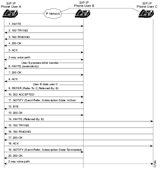
Call Transfer Without Consultation
Figure B-7 illustrates a successful call between Cisco SIP IP phones in which two parties are in a call and then one of the participants transfers the call to a third party without first contacting the third party. This is called a blind or unattended transfer. In this call flow scenario, the end users are User A, User B, and User C. They are all using Cisco SIP IP phones, which are connected via an IP network.
The call flow scenario is as follows:
1. User A calls User B.
2. User B answers the call.
3. User B transfers the call to User C.
Figure B-7 Call Transfer Without Consultation
Step
|
Action
|
Description
|
1.
|
INVITE—Phone A to Phone B
|
Phone A sends a SIP INVITE request to Phone B. The request is an invitation to User B to participate in a call session. In the INVITE request:
•The phone number of User B is inserted in the Request-URI field in the form of a SIP URL. The SIP URL identifies the address of User B and takes a form similar to an e-mail address (user@host, where user is the telephone number and host is either a domain name or a numeric network address). For example, the Request-URI field in the INVITE request to User B appears as "INVITE sip:555-0199@companyb.com; user=phone." The "user=phone" parameter distinquishes that the Request-URI address is a telephone number rather than a username.
•Phone A is identified as the call session initiator in the From field.
•A unique numeric identifier is assigned to the call and is inserted in the Call-ID field.
•The transaction number within a single call leg is identified in the CSeq field.
•The media capability that User A is ready to receive is specified.
|
2.
|
100 Trying—Phone B to Phone A
|
Phone B sends a SIP 100 Trying response to Phone A. The response indicates that the INVITE request has been received.
|
3.
|
180 Ringing—Phone B to Phone A
|
Phone B sends a SIP 180 Ringing response to Phone A.
|
4.
|
200 OK—Phone B to Phone A
|
Phone B sends a SIP 200 OK response to Phone A. The response notifies Phone A that the connection has been made.
If Phone B supports the media capability advertised in the INVITE message sent by Phone A, it advertises the intersection of its own and Phone A's media capability in the 200 OK response. If Phone B does not support the media capability advertised by Phone A, it sends back a 400 Bad Request response with a 304 Warning header field.
|
5.
|
ACK—Phone A to Phone B
|
Phone A sends a SIP ACK to Phone B. The ACK confirms that Phone A has received the 200 OK response from Phone B.
The ACK might contain a message body with the final session description to be used by Phone B. If the message body of the ACK is empty, Phone B uses the session description in the INVITE request.
|
A two-way RTP channel is established between Phone A and Phone B.
User B then selects the option to blind transfer the call to User C.
|
6.
|
INVITE—Phone B to Phone A
|
Phone B sends a midcall INVITE to Phone A with new Session Description Protocol (SDP) attribute parameter.
SDP: a=sendonly
The a= SDP field of the SIP INVITE contains sendonly. This value places the call on hold.
|
7.
|
200 OK—Phone A to Phone B
|
Phone A sends a SIP 200 OK response to Phone B.
|
8.
|
ACK—Phone B to Phone A
|
Phone B sends a SIP ACK to Phone A. The ACK confirms that Phone B has received the 200 OK response from Phone A.
|
User B dials User C.
|
9.
|
REFER—Phone B to Phone A
|
Phone B sends a REFER message to Phone A. The message contains the following information:
•Refer-To: C
•Referred-By: B
The message indicates that Phone A should send an INVITE request to Phone C.
|
10.
|
202 ACCEPTED—Phone A to Phone B
|
Phone A sends a SIP 202 ACCEPTED message to Phone B. The message confirms that the REFER message has been received.
|
11.
|
NOTIFY (Event:Refer; Subscription-State: Active)
|
Phone A sends a NOTIFY message to Phone B. This message notifies B that the REFER processing has started.
|
12.
|
BYE—Phone B to Phone A
|
Phone B sends a BYE message to Phone A. The message indicates that Phone B will disconnect from the call.
|
13.
|
200 OK—Phone A to Phone B
|
Phone A sends a SIP 200 OK response to Phone B. The response notifies Phone B that the BYE message was received.
|
14.
|
INVITE—Phone A to Phone C
|
Because of the REFER message from Phone B, Phone A sends a SIP INVITE request to Phone C. The request is an invitation to User C to participate in a call session. The request contains the following information:
•Referred-By: B
The message indicates that the INVITE was referred by Phone B.
|
15.
|
100 Trying—Phone C to Phone A
|
Phone C sends a SIP 100 Trying response to Phone A. The response indicates that the INVITE request has been received.
|
16.
|
180 Ringing—Phone C to Phone A
|
Phone C sends a SIP 180 Ringing response to Phone A.
|
17.
|
200 OK—Phone C to Phone A
|
Phone C sends a SIP 200 OK response to Phone A. The response notifies Phone A that the connection has been made.
|
18.
|
ACK—Phone A to Phone C
|
Phone A sends a SIP ACK to Phone C. The ACK confirms that Phone A has received the 200 OK response from Phone C.
|
19.
|
NOTIFY—Phone A to Phone B
|
Phone A sends a NOTIFY message to Phone B. The message notifies Phone C of the REFER event.
|
20.
|
200 OK—Phone B to Phone A
|
Phone B sends a SIP 200 OK response to Phone A. The response notifies Phone A that the NOTIFY message was received.
|
A two-way RTP channel is established between Phone A and Phone C.
|
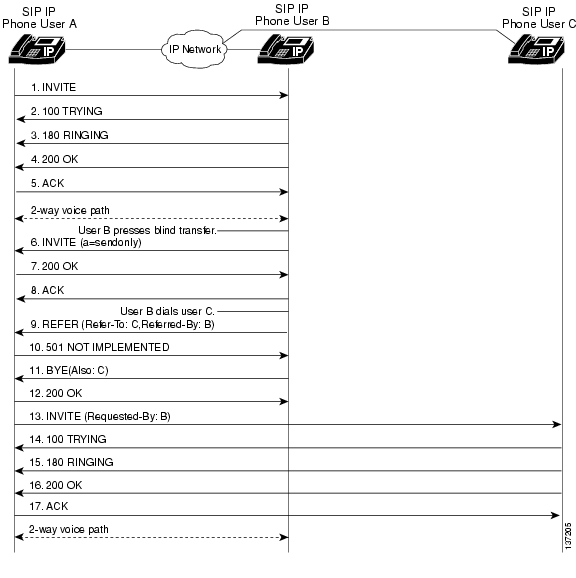
Call Transfer Without Consultation Using Failover
Figure B-8 illustrates a successful call between Cisco SIP IP phones in which two parties are in a call and then one of the participants transfers the call to a third party without first contacting the third party. This is called a blind or unattended transfer. In this call flow scenario, the end users are User A, User B, and User C. They are all using Cisco SIP IP phones, which are connected using an IP network.
The call flow scenario is as follows:
1. User A calls User B.
2. User B answers the call.
3. User B transfers the call to User C.
Figure B-8 Call Transfer Without Consultation Using Failover
Step
|
Action
|
Description
|
1.
|
INVITE—Phone A to Phone B
|
Phone A sends a SIP INVITE request to Phone B. The request is an invitation to User B to participate in a call session. In the INVITE request:
•The phone number of User B is inserted in the Request-URI field in the form of a SIP URL. The SIP URL identifies the address of User B and takes a form similar to an e-mail address (user@host, where user is the telephone number and host is either a domain name or a numeric network address). For example, the Request-URI field in the INVITE request to User B appears as "INVITE sip:555-0199@companyb.com; user=phone." The "user=phone" parameter distinquishes that the Request-URI address is a telephone number rather than a username.
•Phone A is identified as the call session initiator in the From field.
•A unique numeric identifier is assigned to the call and is inserted in the Call-ID field.
•The transaction number within a single call leg is identified in the CSeq field.
•The media capability User A is ready to receive is specified.
|
2.
|
100 Trying—Phone B to Phone A
|
Phone B sends a SIP 100 Trying response to Phone A. The response indicates that the INVITE request has been received.
|
3.
|
180 Ringing—Phone B to Phone A
|
Phone B sends a SIP 180 Ringing response to Phone A.
|
4.
|
200 OK—Phone B to Phone A
|
Phone B sends a SIP 200 OK response to Phone A. The response notifies Phone A that the connection has been made.
If Phone B supports the media capability advertised in the INVITE message sent by Phone A, it advertises the intersection of its own and Phone A's media capability in the 200 OK response. If Phone B does not support the media capability advertised by Phone A, it sends back a 400 Bad Request response with a 304 Warning header field.
|
5.
|
ACK—Phone A to Phone B
|
Phone A sends a SIP ACK to Phone B. The ACK confirms that Phone A has received the 200 OK response from Phone B.
The ACK might contain a message body with the final session description to be used by Phone B. If the message body of the ACK is empty, Phone B uses the session description in the INVITE request.
|
A two-way RTP channel is established between Phone A and Phone B.
User B then selects the option to blind transfer the call to User C.
|
6.
|
INVITE—Phone B to Phone A
|
Phone B sends a midcall INVITE to Phone A with new Session Description Protocol (SDP) attribute parameter.
SDP: a=sendonly
The a= SDP field of the SIP INVITE contains sendonly. This value places the call on hold.
|
7.
|
200 OK—Phone A to Phone B
|
Phone A sends a SIP 200 OK response to Phone B.
|
8.
|
ACK—Phone B to Phone A
|
Phone B sends a SIP ACK to Phone A. The ACK confirms that Phone B has received the 200 OK response from Phone A.
|
User B dials User C.
|
9.
|
REFER—Phone B to Phone A
|
Phone B sends a REFER message to Phone A. The message contains the following information:
•Refer-To: C
•Referred-By: B
The REFER message indicates that Phone A should send an INVITE request to Phone C.
|
10.
|
501 Not Implemented—Cisco SIP IP Phone A to Phone B
|
Phone A sends a 501 Not Implemented message to Phone B. The message indicates that the REFER message is not supported and that Phone B should failover to Bye/Also.
|
11.
|
BYE—Phone B to Phone A
|
Phone B sends a BYE message to Phone A. The message includes the following information:
•Also: C
The message indicates that the 501 Not Implemented message was received in response to a REFER message.
|
12.
|
200 OK—Phone A to Phone B
|
Phone A sends a SIP 200 OK response to Phone B. The response notifies Phone B that the BYE message was received.
|
13.
|
INVITE—Phone A to Phone C
|
Phone A sends a SIP INVITE request to Phone C. The request is an invitation to User C to participate in a call session. The request contains the following information:
•Requested-By: B
The message indicates that the INVITE was requested by Phone B.
|
14.
|
100 Trying—Phone C to Phone A
|
Phone C sends a SIP 100 Trying response to Phone A. The response indicates that the INVITE request has been received.
|
15.
|
180 Ringing—Phone C to Phone A
|
Phone C sends a SIP 180 Ringing response to Phone A.
|
16.
|
200 OK—Phone C to Phone A
|
Phone C sends a SIP 200 OK response to Phone A. The response notifies Phone A that the connection has been made.
|
17.
|
ACK—Phone A to Phone C
|
Phone A sends a SIP ACK to Phone C. The ACK confirms that Phone A has received the 200 OK response from Phone C.
|
A two-way RTP channel is established between Phone A and Phone C.
|
Call Transfer with Consultation
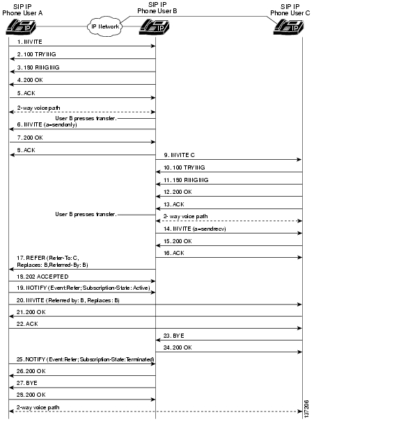
Figure B-9 illustrates a successful call between Cisco SIP IP phones in which two parties are in a call, one of the participants contacts a third party, and then that participant transfers the call to the third party. This is called an attended transfer. In this call flow scenario, the end users are User A, User B, and User C. They are all using Cisco SIP IP phones, which are connected via an IP network.
The call flow scenario is as follows:
1. User A calls User B.
2. User B answers the call.
3. User B calls User C, and User C consents to take the call.
4. User B transfers the call to User C.
5. User B disconnects with User C.
6. User C and User A connect to each other.
Figure B-9 Call Transfer with Consultation
Step
|
Action
|
Description
|
1.
|
INVITE—Phone A to Phone B
|
Phone A sends a SIP INVITE request to Phone B. The request is an invitation to User B to participate in a call session. In the INVITE request:
•The phone number of User B is inserted in the Request-URI field in the form of a SIP URL. The SIP URL identifies the address of User B and takes a form similar to an e-mail address (user@host, where user is the telephone number and host is either a domain name or a numeric network address). For example, the Request-URI field in the INVITE request to User B appears as "INVITE sip:555-0199@companyb.com; user=phone." The "user=phone" parameter distinquishes that the Request-URI address is a telephone number rather than a username.
•Phone A is identified as the call session initiator in the From field.
•A unique numeric identifier is assigned to the call and is inserted in the Call-ID field.
•The transaction number within a single call leg is identified in the CSeq field.
•The media capability User A is ready to receive is specified.
|
2.
|
100 Trying—Phone B to Phone A
|
Phone B sends a SIP 100 Trying response to Phone A. The response indicates that the INVITE request has been received.
|
3.
|
180 Ringing—Phone B to Phone A
|
Phone B sends a SIP 180 Ringing response to Phone A.
|
4.
|
200 OK—Phone B to Phone A
|
Phone B sends a SIP 200 OK response to Phone A. The response notifies Phone A that the connection has been made.
If Phone B supports the media capability advertised in the INVITE message sent by Phone A, it advertises the intersection of its own and Phone A's media capability in the 200 OK response. If Phone B does not support the media capability advertised by Phone A, it sends back a 400 Bad Request response with a 304 Warning header field.
|
5.
|
ACK—Phone A to Phone B
|
Phone A sends a SIP ACK to Phone B. The ACK confirms that Phone A has received the 200 OK response from Phone B.
The ACK might contain a message body with the final session description to be used by Phone B. If the message body of the ACK is empty, Phone B uses the session description in the INVITE request.
|
A two-way RTP channel is established between Phone A and Phone B.
User B then selects the option to transfer the call to User C.
|
6.
|
INVITE—Phone B to Phone A
|
Phone B sends a midcall INVITE to Phone A with new Session Description Protocol (SDP) attribute parameter.
SDP: a=sendonly
The a= SDP field of the SIP INVITE contains sendonly. This value places the call on hold.
|
7.
|
200 OK—Phone A to Phone B
|
Phone A sends a SIP 200 OK response to Phone B.
|
8.
|
ACK—Phone B to Phone A
|
Phone B sends a SIP ACK to Phone A. The ACK confirms that Phone B has received the 200 OK response from Phone A.
|
User B dials User C.
|
9.
|
INVITE—Phone B to Phone C
|
Phone B sends a SIP INVITE request to Phone C. The request is an invitation to User C to participate in a call session.
|
10.
|
100 Trying—Phone C to Phone B
|
Phone C sends a SIP 100 Trying response to Phone B. The response indicates that the INVITE request has been received.
|
11.
|
180 Ringing—Phone C to Phone B
|
Phone C sends a SIP 180 Ringing response to Phone B.
|
12.
|
200 OK—Phone C to Phone B
|
Phone C sends a SIP 200 OK response to Phone B. The response notifies Phone B that the connection has been made.
If Phone B supports the media capability advertised in the INVITE message sent by Phone A, it advertises the intersection of its own and Phone A's media capability in the 200 OK response. If Phone B does not support the media capability advertised by Phone A, it sends back a 400 Bad Request response with a 304 Warning header field.
|
13.
|
ACK—Phone B to Phone C
|
Phone B sends a SIP ACK to Phone C. The ACK confirms that Phone B has received the 200 OK response from Phone C.
The ACK might contain a message body with the final session description to be used by Phone C. If the message body of the ACK is empty, Phone C uses the session description in the INVITE request.
|
A two-way RTP channel is established between Phone B and Phone C.
User B then selects the option to transfer the call to User C.
|
14.
|
INVITE—Phone B to Phone C
|
Phone B sends a midcall INVITE to Phone C with new Session Description Protocol (SDP) attribute parameter.
SDP: a=sendonly
The a= SDP field of the SIP INVITE contains sendonly. This value places the call on hold.
|
15.
|
200 OK—Phone A to Phone B
|
Phone A sends a SIP 200 OK response to Phone B.
|
16.
|
ACK—Phone B to Phone C
|
Phone B sends a SIP ACK to Phone C. The ACK confirms that Phone B has received the 200 OK response from Phone C.
|
17.
|
REFER—Phone B to Phone A
|
Phone B sends a REFER message to Phone A. The message contains the following information:
•Refer-To: C
•Replaces: B
•Referred-By: B
The message indicates that the user (recipient) should contact a third party for use in transferring parties.
|
18.
|
202 ACCEPTED—Phone A to Phone B
|
Phone A sends a SIP 202 ACCEPTED message to Phone B. The confirms that the REFER message has been received.
|
19.
|
NOTIFY (Event:Refer; Subscription-State: Active)
|
Phone A sends a NOTIFY message to Phone B. This message notifies B that the REFER processing has started.
|
20.
|
INVITE—Phone A to Phone C
|
Phone A sends a SIP INVITE request to Phone C. The request contains the following information:
•Referred-By: B
•Replaces: B
|
21.
|
200 OK—Phone C to Phone A
|
Phone C sends a SIP 200 OK response to Phone A. The response notifies Phone A that the INVITE request has been received.
|
22.
|
ACK—Phone A to Phone C
|
Phone A sends a SIP ACK to Phone C. The ACK confirms that Phone A has received the 200 OK response from Phone C.
|
23.
|
BYE—Phone C to Phone B
|
Phone C sends a SIP BYE request to Phone B.
|
24.
|
200 OK—Phone B to Phone C
|
Phone B sends a SIP 200 OK response to Phone C. The response notifies Phone C that the BYE request has been received.
|
25.
|
NOTIFY—Phone A to Phone B
|
Phone A sends a NOTIFY message to Phone B. The message notifies Phone B of the REFER event.
|
26.
|
200 OK—Phone B to Phone A
|
Phone B sends a SIP 200 OK response to Phone A. The response notifies Phone A that the NOTIFY request has been received.
|
27.
|
BYE—Phone B to Phone A
|
Phone B sends a SIP BYE request to Phone A.
|
28.
|
200 OK—Phone A to Phone B
|
Phone A sends a SIP 200 OK response to Phone B. The response notifies Phone A that the BYE request has been received.
|
A two-way RTP channel is established between Phone A and Phone C.
|
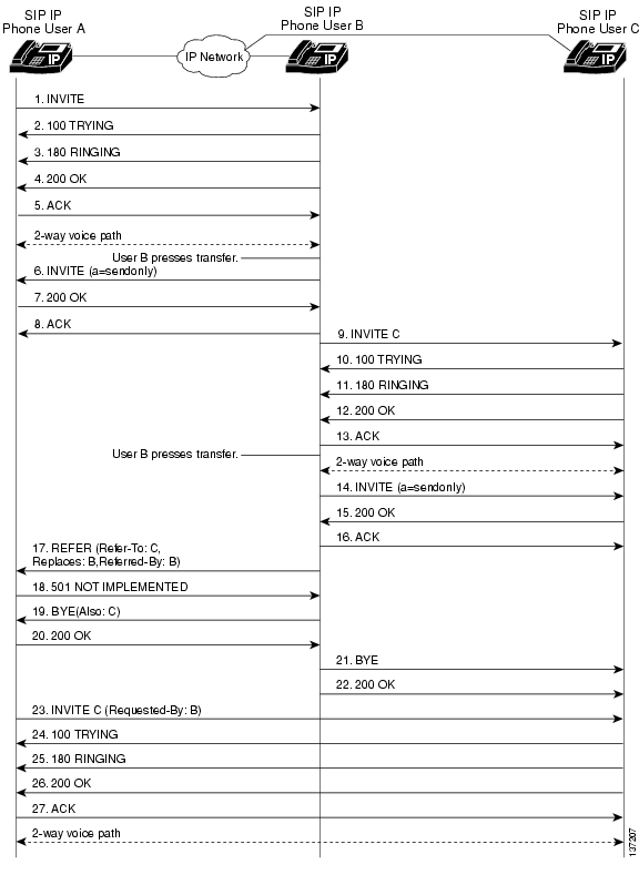
Call Transfer with Consultation Using Failover
Figure B-10 illustrates a successful call between Cisco SIP IP phones in which two parties are in a call, one of the participants contacts a third party, and then that participant transfers the call to the third party. This is called an attended transfer. In this call flow scenario, the end users are User A, User B, and User C. They are all using Cisco SIP IP phones, which are connected via an IP network.
The call flow scenario is as follows:
1. User A calls User B.
2. User B answers the call.
3. User B calls User C, and User C consents to take the call.
4. User B transfers the call to User C.
5. User B disconnects with User C.
6. User C and User A connect to each other.
Figure B-10 Call Transfer with Consultation Using Failover
Step
|
Action
|
Description
|
1.
|
INVITE—Phone A to Phone B
|
Phone A sends a SIP INVITE request to Phone B. The request is an invitation to User B to participate in a call session. In the INVITE request:
•The phone number of User B is inserted in the Request-URI field in the form of a SIP URL. The SIP URL identifies the address of User B and takes a form similar to an e-mail address (user@host, where user is the telephone number and host is either a domain name or a numeric network address). For example, the Request-URI field in the INVITE request to User B appears as "INVITE sip:555-0199@companyb.com; user=phone." The "user=phone" parameter distinquishes that the Request-URI address is a telephone number rather than a username.
•Phone A is identified as the call session initiator in the From field.
•A unique numeric identifier is assigned to the call and is inserted in the Call-ID field.
•The transaction number within a single call leg is identified in the CSeq field.
•The media capability User A is ready to receive is specified.
|
2.
|
100 Trying—Phone B to Phone A
|
Phone B sends a SIP 100 Trying response to Phone A. The response indicates that the INVITE request has been received.
|
3.
|
180 Ringing—Phone B to Phone A
|
Phone B sends a SIP 180 Ringing response to Phone A.
|
4.
|
200 OK—Phone B to Phone A
|
Phone B sends a SIP 200 OK response to Phone A. The response notifies Phone A that the connection has been made.
If Phone B supports the media capability advertised in the INVITE message sent by Phone A, it advertises the intersection of its own and Phone A's media capability in the 200 OK response. If Phone B does not support the media capability advertised by Phone A, it sends back a 400 Bad Request response with a 304 Warning header field.
|
5.
|
ACK—Phone A to Phone B
|
Phone A sends a SIP ACK to Phone B. The ACK confirms that Phone A has received the 200 OK response from Phone B.
The ACK might contain a message body with the final session description to be used by Phone B. If the message body of the ACK is empty, Phone B uses the session description in the INVITE request.
|
A two-way RTP channel is established between Phone A and Phone B.
User B then selects the option to transfer the call to User C.
|
6.
|
INVITE—Phone B to Phone A
|
Phone B sends a midcall INVITE to Phone A with new Session Description Protocol (SDP) attribute parameter.
SDP: a=sendonly
|
7.
|
200 OK—Phone A to Phone B
|
Phone A sends a SIP 200 OK response to Phone B.
|
8.
|
ACK—Phone B to Phone A
|
Phone B sends a SIP ACK to Phone A. The ACK confirms that Phone B has received the 200 OK response from Phone A.
|
User B dials User C.
|
9.
|
INVITE—Phone B to Phone C
|
Phone B sends a SIP INVITE request to Phone C. The request is an invitation to User C to participate in a call session.
|
10.
|
100 Trying—Phone C to Phone B
|
Phone C sends a SIP 100 Trying response to Phone B. The response indicates that the INVITE request has been received.
|
11.
|
180 Ringing—Phone C to Phone B
|
Phone C sends a SIP 180 Ringing response to Phone B.
|
12.
|
200 OK—Phone C to Phone B
|
Phone C sends a SIP 200 OK response to Phone B. The response notifies Phone B that the connection has been made.
If Phone B supports the media capability advertised in the INVITE message sent by Phone A, it advertises the intersection of its own and Phone A's media capability in the 200 OK response. If Phone B does not support the media capability advertised by Phone A, it sends back a 400 Bad Request response with a 304 Warning header field.
|
13.
|
ACK—Phone B to Phone C
|
Phone B sends a SIP ACK to Phone C. The ACK confirms that Phone B has received the 200 OK response from Phone C.
The ACK might contain a message body with the final session description to be used by Phone C. If the message body of the ACK is empty, Phone C uses the session description in the INVITE request.
|
A two-way RTP channel is established between Phone B and Phone C.
User B then selects the option to transfer the call to User C.
|
14.
|
INVITE—Phone B to Phone C
|
Phone B sends a midcall INVITE to Phone C with new Session Description Protocol (SDP) attribute parameter.
SDP: a=sendonly
The a= SDP field of the SIP INVITE contains sendonly. This value places the call on hold.
|
15.
|
200 OK—Phone C to Phone B
|
Phone C sends a SIP 200 OK response to Phone B.
|
16.
|
ACK—Phone B to Phone C
|
Phone B sends a SIP ACK to Phone C. The ACK confirms that Phone B has received the 200 OK response from Phone C.
|
17.
|
REFER—Phone B to Phone A
|
Phone B sends a REFER message to Phone A. The message contains the following information:
•Refer-To: C
•Replaces: B
•Referred-By: B
The message indicates that the user (recipient) should contact a third party for use in transferring parties.
|
18.
|
501 Not Implemented—Cisco SIP IP Phone A to Cisco SIP IP Phone B
|
Phone A sends a 501 Not Implemented message to Phone B. The message indicates that the REFER message is not supported and that Phone B should failover to Bye/Also.
|
19.
|
BYE—Phone B to Phone A
|
Phone B sends a BYE message to Phone A. The message includes the following information:
•Also: C
The message indicates that the 501 Not Implemented message was received in response to a REFER message.
|
20.
|
200 OK—Phone A to Phone B
|
Phone A sends a SIP 200 OK response to Phone B. The response notifies Phone B that the BYE request has been received.
|
21.
|
BYE—Phone B to Phone C
|
Phone B sends a SIP BYE request to Phone C.
|
22.
|
200 OK—Phone C to Phone B
|
Phone C sends a SIP 200 OK response to Phone B. The response notifies Phone B that the BYE request has been received.
|
23.
|
INVITE—Phone A to Phone C
|
Phone A sends a SIP INVITE request to Phone C. The request contains the following information:
•Requested-By: B
The message indicates that the INVITE was requested by Phone B.
|
24.
|
100 Trying—Phone C to Phone A
|
Phone C sends a SIP 100 Trying response to Phone A. The response indicates that the INVITE request has been received.
|
25.
|
180 Ringing—Phone C to Phone A
|
Phone C sends a SIP 180 Ringing response to Phone A.
|
26.
|
200 OK—Phone C to Phone A
|
Phone C sends a SIP 200 OK response to Phone A. The response notifies Phone A that the connection has been made.
|
27.
|
ACK—Phone A to Phone C
|
Phone A sends a SIP ACK to Phone C. The ACK confirms that Phone A has received the 200 OK response from Phone C.
|
A two-way RTP channel is established between Phone A and Phone C.
|
Network Call Forwarding (Unconditional)
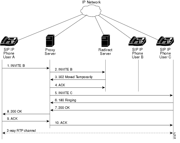
Figure B-11 illustrates successful call forwarding between Cisco SIP IP phones in which User B has requested unconditional call forwarding from the network. When User A calls User B, the call is immediately transferred to Phone C. In this call flow scenario, the end users are User A, User B, and User C. They are all using Cisco SIP IP phones, which are connected via an IP network.
The call flow scenario is as follows:
1. User B requests that the network forward all calls to Phone C.
2. User A calls User B.
3. The network transfers the call to Phone C.
Figure B-11 Network Call Forwarding (Unconditional)
Step
|
Action
|
Description
|
1.
|
INVITE—Phone A to SIP proxy server
|
Phone A sends a SIP INVITE request to the SIP proxy server. The request is an invitation to User B to participate in a call session. In the INVITE request:
•The phone number of User B is inserted in the Request-URI field in the form of a SIP URL. The SIP URL identifies the address of User B and takes a form similar to an e-mail address (user@host, where user is the telephone number and host is either a domain name or a numeric network address). For example, the Request-URI field in the INVITE request to User B appears as "INVITE sip:555-0199@companyb.com; user=phone." The "user=phone" parameter distinquishes that the Request-URI address is a telephone number rather than a username.
•Phone A is identified as the call session initiator in the From field.
•A unique numeric identifier is assigned to the call and is inserted in the Call-ID field.
•The transaction number within a single call leg is identified in the CSeq field.
•The media capability User A is ready to receive is specified.
|
2.
|
INVITE—SIP proxy server to SIP redirect server
|
The SIP proxy server sends the SIP INVITE request to the SIP redirect server.
|
3.
|
302 Moved Temporarily—SIP redirect server to SIP proxy server
|
The SIP redirect server sends a SIP 302 Moved temporarily message to the SIP proxy server. The message indicates that User B is not available at Phone B and includes instructions to locate User B at Phone C.
|
4.
|
ACK—SIP proxy server to redirect server
|
The SIP proxy server sends the SIP ACK to the SIP redirect server.
|
5.
|
INVITE—SIP proxy server to Phone C
|
The SIP proxy server sends a SIP INVITE request to Phone C. The request is an invitation to User C to participate in a call session.
|
6.
|
180 Ringing—Phone C to SIP proxy server
|
Phone C sends a SIP 180 Ringing response to the SIP proxy server.
|
7.
|
200 OK—Phone C to SIP proxy server
|
Phone C sends a SIP 200 OK response to the SIP proxy server.
|
8.
|
200 OK—SIP proxy server to Phone A
|
The SIP proxy server forwards the SIP 200 OK response to Phone A.
|
9.
|
ACK—Phone A to SIP proxy server
|
Phone A sends a SIP ACK to the SIP proxy server. The ACK confirms that the SIP proxy server has received the 200 OK response from Phone C.
|
10.
|
ACK—SIP proxy server to Phone C
|
The SIP proxy server forwards the SIP ACK to the Phone C. The ACK confirms that Phone A has received the 200 OK response from Phone C.
|
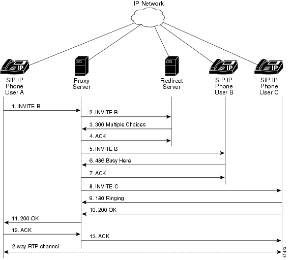
Network Call Forwarding (Busy)
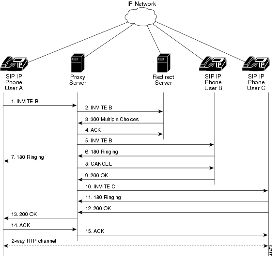
Figure B-12 illustrates successful call forwarding between Cisco SIP IP phones in which User B has requested call forwarding from the network in the event the phone is busy. When User A calls User B, the SIP proxy server tries to place the call to Phone B, and, if the line is busy, the call is transferred to Phone C. In this call flow scenario, the end users are User A, User B, and User C. They are all using Cisco SIP IP phones, which are connected via an IP network.
The call flow scenario is as follows:
1. User B requests that if Phone B is busy, the network should forward incoming calls to Phone C.
2. User A calls User B.
3. User B is busy.
4. The network transfers the call to Phone C.
Figure B-12 Network Call Forwarding (Busy)
Step
|
Action
|
Description
|
1.
|
INVITE—Phone A to SIP proxy server
|
Phone A sends a SIP INVITE request to the SIP proxy server. The request is an invitation to User B to participate in a call session. In the INVITE request:
•The phone number of User B is inserted in the Request-URI field in the form of a SIP URL. The SIP URL identifies the address of User B and takes a form similar to an e-mail address (user@host, where user is the telephone number and host is either a domain name or a numeric network address). For example, the Request-URI field in the INVITE request to User B appears as "INVITE sip:555-0199@companyb.com; user=phone." The "user=phone" parameter distinquishes that the Request-URI address is a telephone number rather than a username.
•Phone A is identified as the call session initiator in the From field.
•A unique numeric identifier is assigned to the call and is inserted in the Call-ID field.
•The transaction number within a single call leg is identified in the CSeq field.
•The media capability User A is ready to receive is specified.
|
2.
|
INVITE—SIP proxy server to SIP redirect server
|
The SIP proxy server sends the SIP INVITE request to the SIP redirect server.
|
3.
|
300 Multiple Choices—SIP redirect server to SIP proxy server
|
The SIP redirect server sends a SIP 300 Multiple choices message to the SIP proxy server. The message indicates that User B can be reached either at Phone B or Phone C.
|
4.
|
ACK—SIP proxy server to redirect server
|
The SIP proxy server sends the SIP ACK to the SIP redirect server.
|
5.
|
INVITE—SIP proxy server to Phone B
|
The SIP proxy server sends a SIP INVITE request to Phone B. The request is an invitation to User B to participate in a call session.
|
6.
|
486 Busy Here—Phone B to SIP proxy server
|
Phone B sends a 486 Busy here message to the SIP proxy server. The message indicates that Phone B is in use and the user is not willing or able to take additional calls.
|
7.
|
ACK—SIP proxy server to
Phone B
|
The SIP proxy server forwards the SIP ACK to the Phone B. The ACK confirms that the SIP proxy server has received the 486 Busy here response from Phone B.
|
8.
|
INVITE—SIP proxy server to Phone C
|
The SIP proxy server sends a SIP INVITE request to Phone C. The request is an invitation to User C to participate in a call session.
|
9.
|
180 Ringing—Phone C to SIP proxy server
|
Phone C sends a SIP 180 Ringing response to the SIP proxy server.
|
10.
|
200 OK—Phone C to SIP proxy server
|
Phone C sends a SIP 200 OK response to the SIP proxy server.
|
11.
|
200 OK—SIP proxy server to Phone A
|
The SIP proxy server forwards the SIP 200 OK response to Phone A.
|
12.
|
ACK—Phone A to SIP proxy server
|
Phone A sends a SIP ACK to the SIP proxy server. The ACK confirms that Phone A has received the 200 OK response from Phone C.
|
13.
|
ACK—SIP proxy server to Phone C
|
The SIP proxy server forwards the SIP ACK to the Phone C. The ACK confirms that Phone A has received the 200 OK response from Phone C.
|
Network Call Forwarding (No Answer)
Figure B-13 illustrates successful call forwarding between Cisco SIP IP phones in which User B has requested call forwarding from the network in the event that there is no answer. When User A calls User B, the proxy server tries to place the call to Phone B, and, if there is no answer, the call is transferred to Phone C. In this call flow scenario, the end users are User A, User B, and User C. They are all using Cisco SIP IP phones, which are connected via an IP network.
The call flow scenario is as follows:
1. User B requests that if the phone (Phone B) is not answered within a set amount of time, the network should forward incoming calls to Phone C.
2. User A calls User B.
3. User B does not answered.
4. The network transfers the call to Phone C.
Figure B-13 Network Call Forwarding (No Answer)
Step
|
Action
|
Description
|
1.
|
INVITE—Phone A to SIP proxy server
|
Phone A sends a SIP INVITE request to the SIP proxy server. The request is an invitation to User B to participate in a call session. In the INVITE request:
•The phone number of User B is inserted in the Request-URI field in the form of a SIP URL. The SIP URL identifies the address of User B and takes a form similar to an e-mail address (user@host, where user is the telephone number and host is either a domain name or a numeric network address). For example, the Request-URI field in the INVITE request to User B appears as "INVITE sip:555-0199@companyb.com; user=phone." The "user=phone" parameter distinquishes that the Request-URI address is a telephone number rather than a username.
•Phone A is identified as the call session initiator in the From field.
•A unique numeric identifier is assigned to the call and is inserted in the Call-ID field.
•The transaction number within a single call leg is identified in the CSeq field.
•The media capability User A is ready to receive is specified.
|
2.
|
INVITE—SIP proxy server to SIP redirect server
|
The SIP proxy server sends the SIP INVITE request to the SIP redirect server.
|
3.
|
300 Multiple Choices—SIP redirect server to SIP proxy server
|
The SIP redirect server sends a SIP 300 Multiple choices message to the SIP proxy server. The message indicates that User B can be reached either at Phone B or Phone C.
|
4.
|
ACK—SIP proxy server to redirect server
|
The SIP proxy server sends the SIP ACK to the SIP redirect server.
|
5.
|
INVITE—SIP proxy server to Phone B
|
The SIP proxy server sends a SIP INVITE request to Phone B. The request is an invitation to User B to participate in a call session.
|
6.
|
180 Ringing—Phone B to SIP proxy server
|
Phone B sends a SIP 180 Ringing response to the SIP proxy server.
|
7.
|
180 Ringing—SIP proxy server to Phone A
|
The SIP proxy server sends a SIP 180 Ringing response to Phone A.
|
The timeout expires before the phone is answered.
|
8.
|
CANCEL (Ring Timeout)—SIP proxy server to Phone B
|
The SIP proxy server sends a CANCEL request to Phone B to cancel the invitation.
|
9.
|
200 OK—Phone B to SIP proxy server
|
Phone B sends a SIP 200 OK response to the SIP proxy server. The response confirms receipt of the cancellation request.
|
10.
|
INVITE—SIP proxy server to Phone C
|
The SIP proxy server sends a SIP INVITE request to Phone C. The request is an invitation to User C to participate in a call session.
|
11.
|
180 Ringing—Phone C to SIP proxy server
|
Phone C sends a SIP 180 Ringing response to the SIP proxy server.
|
12.
|
200 OK—Phone C to SIP proxy server
|
Phone C sends a SIP 200 OK response to the SIP proxy server.
|
13.
|
200 OK—SIP proxy server to Phone A
|
The SIP proxy server forwards the SIP 200 OK response to Phone A.
|
14.
|
ACK—Phone A to SIP proxy server
|
Phone A sends a SIP ACK to the SIP proxy server. The ACK confirms that Phone A has received the 200 OK response from Phone C.
|
15.
|
ACK—SIP proxy server to Phone C
|
The SIP proxy server forwards the SIP ACK to the Phone C. The ACK confirms that Phone A has received the 200 OK response from Phone C.
|
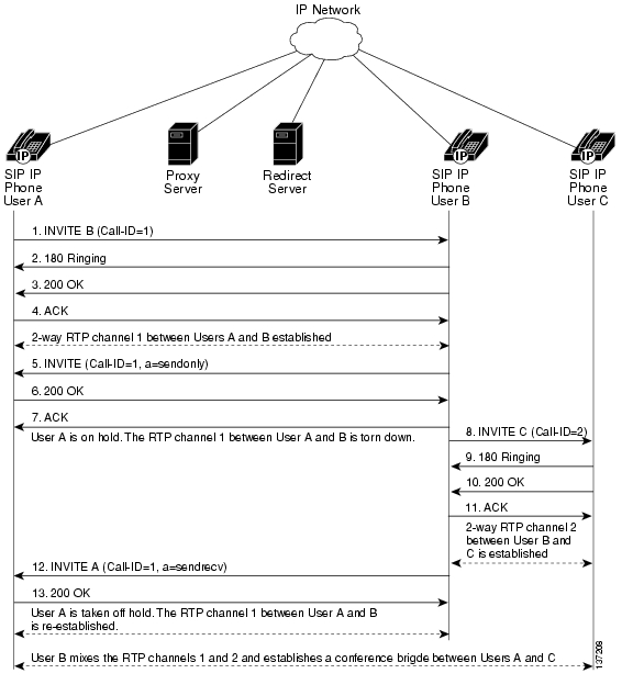
Three-Way Calling
Figure B-14 illustrates successful three-way calling between Cisco SIP IP phones in which User B mixes two RTP channels and therefore establishes a conference bridge between User A and User C. In this call flow scenario, the end users are User A, User B, and User C. They are all using Cisco IP phone 7960G/7940G models, which are connected using an IP network.
The call flow scenario is as follows:
1. User A calls User B.
2. User B answers the call.
3. User B puts User A on hold.
4. User B calls User C.
5. User C answers the call.
6. User B takes User A off hold.
Figure B-14 Three-Way Calling
Step
|
Action
|
Description
|
1.
|
INVITE—Phone A to Phone B
|
Phone A sends a SIP INVITE request to Phone B. The request is an invitation to User B to participate in a call session. In the INVITE request:
•The phone number of User B is inserted in the Request-URI field in the form of a SIP URL. The SIP URL identifies the address of User B and takes a form similar to an e-mail address (user@host, where user is the telephone number and host is either a domain name or a numeric network address). For example, the Request-URI field in the INVITE request to User B appears as "INVITE sip:555-0199@companyb.com; user=phone." The "user=phone" parameter distinquishes that the Request-URI address is a telephone number rather than a username.
•Phone A is identified as the call session initiator in the From field.
•A unique numeric identifier is assigned to the call and is inserted in the Call-ID field.
•The transaction number within a single call leg is identified in the CSeq field.
•The media capability A is ready to receive is specified.
|
2.
|
180 Ringing—Phone B to Phone A
|
Phone B sends a SIP 180 Ringing response to Phone A.
|
3.
|
200 OK—Phone B to Phone A
|
Phone B sends a SIP 200 OK response to Phone A. The response notifies Phone A that the connection has been made.
If Phone B supports the media capability advertised in the INVITE message sent by Phone A, it advertises the intersection of its own and Phone A's media capability in the 200 OK response. If Phone B does not support the media capability advertised by Phone A, it sends back a 400 Bad Request response with a 304 Warning header field.
|
4.
|
ACK—Phone A to Phone B
|
Phone A sends a SIP ACK to Phone B. The ACK confirms that Phone A has received the 200 OK response from Phone B.
The ACK might contain a message body with the final session description to be used by Phone B. If the message body of the ACK is empty, Phone B uses the session description in the INVITE request.
|
A two-way RTP channel is established between Phone A and Phone B.
|
5.
|
INVITE—Phone B to Phone A
|
Phone B sends a midcall INVITE to Phone A with new Session Description Protocol (SDP) attribute parameter.
SDP: a=sendonly
The a= SDP field of the SIP INVITE contains sendonly. This value places the call on hold.
|
6.
|
200 OK—Phone A to Phone B
|
Phone A sends a SIP 200 OK response to Phone B.
|
7.
|
ACK—Phone B to Phone A
|
Phone B sends a SIP ACK to Phone A. The ACK confirms that Phone B has received the 200 OK response from Phone A.
|
The RTP channel between Phone A and Phone B is torn down. A is put on hold.
|
8.
|
INVITE—Phone B to Phone C
|
Phone B sends a SIP INVITE request to Phone C. The request is an invitation to Phone B to participate in a call session. In the INVITE request:
•The phone number of Phone B is inserted in the Request-URI field in the form of a SIP URL. The SIP URL identifies the address of B and takes a form similar to an e-mail address (user@host, where user is the telephone number and host is either a domain name or a numeric network address). For example, the Request-URI field in the INVITE request to C appears as "INVITE sip:555-0199@companyb.com; user=phone." The "user=phone" parameter distinquishes that the Request-URI address is a telephone number rather than a username.
•Phone B is identified as the call session initiator in the From field.
•A unique numeric identifier is assigned to the call and is inserted in the Call-ID field.
•The transaction number within a single call leg is identified in the CSeq field.
•The media capability B is ready to receive is specified.
|
9.
|
180 Ringing—Phone C to Phone B
|
Phone C sends a SIP 180 Ringing response to Phone B.
|
10.
|
200 OK—Phone C to Phone B
|
Phone C sends a SIP 200 OK response to Phone B. The response notifies Phone B that the connection has been made.
If Phone C supports the media capability advertised in the INVITE message sent by Phone B, it advertises the intersection of its own and Phone B's media capability in the 200 OK response. If Phone C does not support the media capability advertised by Phone B, it sends back a 400 Bad Request response with a 304 Warning header field.
|
11.
|
ACK—Phone B to Phone C
|
Phone B sends a SIP ACK to Phone C. The ACK confirms that Phone B has received the 200 OK response from Phone C.
The ACK might contain a message body with the final session description to be used by Phone C. If the message body of the ACK is empty, Phone C uses the session description in the INVITE request.
|
A two-way RTP channel is established between SIP IP Phone B and SIP IP Phone C.
|
12.
|
INVITE—Phone B to Phone A
|
User B takes User A off hold. Phone B sends a SIP INVITE request to Phone A with the same call ID as the previous INVITE and a new SDP attribute parameter (sendrecv), which is used to reestablish the call.
|
13.
|
200 OK—Phone A to Phone B
|
Phone A sends a SIP 200 OK response to Phone B.
|
A is taken off hold. The RTP channel 1 between A and B is reestablished.
|
Phone B acts as a bridge mixing the RTP channel between A and B with the channel between B and C, establishing a conference bridge between A and C.
|
Call from a Cisco SIP IP Phone to a Gateway Acting As a Backup Proxy in a SIP Network
Figure B-15 illustrates a successful call from a Cisco SIP IP phone to a gateway acting as a backup proxy.
Figure B-15 Call from a Cisco SIP IP Phone to a Gateway Acting As a Backup Proxy
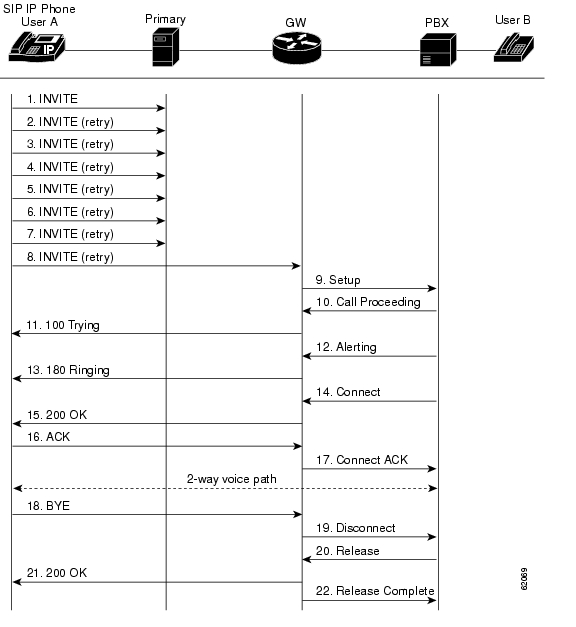
Step
|
Action
|
Description
|
1.
|
INVITE—Cisco SIP IP phone to primary proxy
|
The phone tries to connect to the proxy by sending out the INVITE message.
|
2.
|
INVITE—Cisco SIP IP phone to primary proxy (second try)
|
The phone retries a second time to connect to the proxy by sending out the INVITE message.
|
3.
|
INVITE—Cisco SIP IP phone to primary proxy (third try)
|
The phone retries a third time to connect to the proxy by sending out the INVITE message.
|
4.
|
INVITE—Cisco SIP IP phone to primary proxy (fourth try)
|
The phone retries a fourth time to connect to the proxy by sending out the INVITE message.
|
5.
|
INVITE—Cisco SIP IP phone to primary proxy (fifth try)
|
The phone retries a fifth time to connect to the proxy by sending out the INVITE message.
|
6.
|
INVITE—Cisco SIP IP phone to primary proxy (sixth try)
|
The phone retries a sixth time to connect to the proxy by sending out the INVITE message.
|
7.
|
INVITE—Cisco SIP IP phone to primary proxy (seventh try)
|
The phone retries a seventh time to connect to the proxy. If the connection is not successful after this trial, the "Network Delay, Trying Backup" message displays on the phone.
|
8.
|
INVITE—Cisco SIP IP phone to the gateway (backup proxy)
|
The phone tries to connect to the gateway (backup proxy) by sending out the INVITE message.
|
9.
|
Setup—Gateway to the PBX
|
Call setup is initiated between the gateway and the PBX. The setup includes the standard transactions that take place as A attempts to call B.
|
10.
|
Call Proceeding—PBX to the gateway
|
The PBX sends a Call Proceeding message to the gateway to acknowledge the Call Setup request.
|
11.
|
100 Trying—Gateway to Cisco SIP IP phone (A)
|
The gateway sends a SIP 100 Trying response to A. The response indicates that the INVITE request has been received.
|
12.
|
Alerting—PBX to the gateway
|
The PBX sends an Alert message to the gateway. The message indicates that the PBX has received a 100 Trying Ringing response from the gateway.
|
13.
|
180 Ringing—Gateway to Cisco SIP IP phone (A)
|
The gateway sends a SIP 180 Ringing response to A. The response indicates that the gateway is being alerted.
|
14.
|
Connect—PBX to the gateway
|
The PBX sends a Connect message to the gateway. The message notifies the gateway that the connection has been made.
|
15.
|
200 OK—Gateway to Cisco SIP IP phone (A)
|
The gateway sends a SIP 200 OK response to A. The response notifies A that the connection has been made.
|
16.
|
ACK—Cisco SIP IP phone (A) to the gateway
|
A sends a SIP ACK to the gateway. The ACK confirms that A has received the 200 OK response. The call session is now active.
|
17.
|
Connect ACK—Gateway to the PBX
|
The gateway acknowledges PBX Connect message.
|
18.
|
BYE—Cisco SIP IP phone
(A) to the gateway
|
A terminates the call session and sends a SIP BYE request to the gateway. The request indicates that A wants to release the call.
|
19.
|
Disconnect—Gateway to the PBX
|
The gateway sends a Disconnect message to the PBX.
|
20.
|
Release—PBX to the gateway
|
The PBX sends a Release message to the gateway.
|
21.
|
200 OK—Gateway to Cisco SIP IP phone (A)
|
The gateway sends a SIP 200 OK response to A. The response notifies A that the gateway has received the BYE request.
|
22.
|
Release Complete—Gateway to the PBX
|
The gateway sends a Release Complete message to the PBX, and the call session terminates.
|
Call from a Cisco SIP IP Phone to a Cisco SIP IP Phone Using a SIP Backup Proxy
Figure B-16 illustrates a successful call from a Cisco SIP IP phone to a Cisco SIP IP phone that uses a SIP backup proxy.
Figure B-16 A Successful Call from a Cisco SIP IP Phone to a Cisco SIP IP Phone Using a SIP Backup Proxy
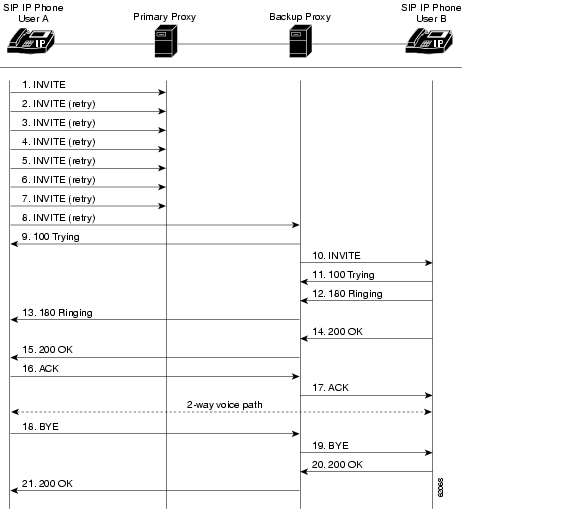
Step
|
Action
|
Description
|
1.
|
INVITE—Cisco SIP IP phone (A) to primary proxy
|
The phone tries to connect to the primary proxy by sending out the INVITE message.
|
2.
|
INVITE—Cisco SIP IP phone (A) to primary proxy (second try)
|
The phone retries a second time to connect to the primary proxy by sending out the INVITE message.
|
3.
|
INVITE—Cisco SIP IP phone (A) to primary proxy (third try)
|
The phone retries a third time to connect to the primary proxy by sending out the INVITE message.
|
4.
|
INVITE—Cisco SIP IP phone (A) to primary proxy (fourth try)
|
The phone retries a fourth time to connect to the primary proxy by sending out the INVITE message.
|
5.
|
INVITE—Cisco SIP IP phone (A) to primary proxy (fifth try)
|
The phone retries a fifth time to connect to the primary proxy by sending out the INVITE message.
|
6.
|
INVITE—Cisco SIP IP phone (A) to primary proxy (sixth try)
|
The phone retries a sixth time to connect to the primary proxy by sending out the INVITE message.
|
7.
|
INVITE—Cisco SIP IP phone (A) to primary proxy (seventh try)
|
The phone retries a seventh time to connect to the primary proxy. If the connection is not successful after this trial, the "Network Delay, Trying Backup" message displays on the Phone.
|
8.
|
INVITE—Cisco SIP IP phone (A) to backup proxy
|
The phone tries to connect to the backup proxy by sending out the INVITE message.
|
9.
|
100 Trying—Backup proxy to Cisco SIP IP phone (A)
|
The backup proxy sends a SIP 100 Trying response to the phone. The response indicates that the INVITE request has been received.
|
10.
|
INVITE—Backup proxy to Cisco SIP IP phone (B)
|
The backup proxy tries to connect to B by sending out the INVITE message.
|
11.
|
100 Trying—Cisco SIP IP phone (B) to backup proxy
|
Phone B sends a SIP 100 Trying response to the backup proxy. The response indicates that the INVITE request has been received.
|
12.
|
180 Ringing—Cisco SIP IP phone (B) to backup proxy
|
Phone B sends a SIP 180 Ringing response to the backup proxy. The response indicates that B is being alerted.
|
13.
|
180 Ringing—Backup proxy to Cisco SIP IP phone (A)
|
The backup proxy sends a SIP 180 Ringing response to A. The response indicates that the backup proxy is being alerted.
|
14.
|
200 OK—Cisco SIP IP phone (B) to backup proxy
|
Phone B sends a SIP 200 OK response to the backup proxy. The response notifies the backup proxy that the connection has been made.
|
15.
|
200 OK—Backup proxy to
Cisco SIP IP phone (A)
|
The backup proxy sends a SIP 200 OK response to Phone A. The response notifies Phone A that the connection has been made.
|
16.
|
ACK—Cisco SIP IP phone (A) to backup proxy
|
Phone A acknowledges the backup proxy Connect message.
|
17.
|
ACK—Backup proxy to
Cisco SIP IP phone (B)
|
The backup proxy acknowledges the Phone B Connect message.
|
18.
|
BYE—Cisco SIP IP phone
(A) to backup proxy
|
A terminates the call session and sends a SIP BYE request to the backup proxy. The request indicates that User A wants to release the call.
|
19.
|
BYE—Backup proxy to
Cisco SIP IP phone (B)
|
The backup proxy terminates the call session and sends a SIP BYE request to User B. The request indicates that the backup proxy wants to release the call.
|
20.
|
200 OK—Cisco SIP IP phone (B) to backup proxy
|
User B sends a SIP 200 OK response to the backup proxy. The response notifies the backup proxy that B has received the BYE request.
|
21.
|
200 OK—Backup proxy to
Cisco SIP IP phone (A)
|
The backup proxy sends a SIP 200 OK response to User A. The response notifies User A that the backup proxy has received the BYE request.
|
Call from a Cisco SIP IP Phone to a Cisco SIP IP Phone Using a SIP Emergency Proxy
Figure B-17 illustrates a successful call from a Cisco SIP IP phone to a Cisco SIP IP phone via an emergency proxy. B is the extension of the dial template with the "Route" attribute as "emergency" in the dialplan.xml file.
Figure B-17 Successful Call from a Cisco IP Phone to a Cisco IP Phone Using a SIP Emergency Proxy
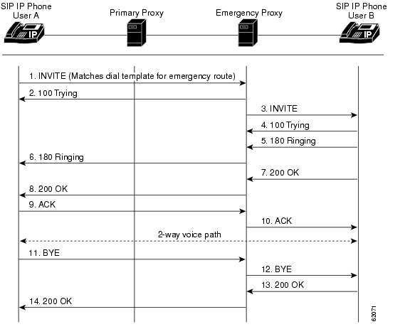
Step
|
Action
|
Description
|
1.
|
INVITE—Cisco SIP IP phone (A) to emergency proxy
|
The phone tries to connect to the emergency proxy by sending out the INVITE message. The dial template for the emergency route is matched.
|
2.
|
100 Trying—Emergency proxy to Cisco SIP IP phone (A)
|
The emergency proxy sends a SIP 100 Trying response to A. The response indicates that the INVITE request has been received.
|
3.
|
INVITE—Emergency proxy to Cisco SIP IP phone (B)
|
The backup proxy tries to connect to B by sending out the INVITE message.
|
4.
|
100 Trying—Cisco SIP IP phone (B) to emergency proxy
|
User B sends a SIP 100 Trying response to the emergency proxy. The response indicates that the INVITE request has been received.
|
5.
|
180 Ringing—Cisco SIP IP phone (B) to emergency proxy
|
User B sends a SIP 180 Ringing response to the emergency proxy. The response indicates that User B is being alerted.
|
6.
|
180 Ringing—Emergency proxy to Cisco SIP IP phone (A)
|
The emergency proxy sends a SIP 180 Ringing response to User A. The response indicates that the emergency proxy is being alerted.
|
7.
|
200 OK—Cisco SIP IP phone (B) to emergency proxy
|
User B sends a SIP 200 OK response to the emergency proxy. The response notifies the emergency proxy that the connection has been made.
|
8.
|
200 OK—Emergency proxy to Cisco SIP IP phone (A)
|
The emergency proxy sends a SIP 200 OK response to User A. The response notifies User A that the connection has been made.
|
9.
|
ACK—Cisco SIP IP phone
(A) to emergency proxy
|
A acknowledges the emergency proxy's Connect message.
|
10.
|
ACK—Emergency proxy to Cisco SIP IP phone (B)
|
The emergency proxy acknowledges B's Connect message.
|
11.
|
BYE—Cisco SIP IP phone
(A) to emergency proxy
|
A terminates the call session and sends a SIP BYE request to the emergency proxy. The request indicates that A wants to release the call.
|
12.
|
BYE—Emergency proxy to Cisco SIP IP phone (B)
|
The emergency proxy terminates the call session and sends a SIP BYE request to User B. The request indicates that the emergency proxy wants to release the call.
|
13.
|
200 OK—Cisco SIP IP phone (B) to emergency proxy
|
User B sends a SIP 200 OK response to the emergency proxy. The response notifies the emergency proxy that B has received the BYE request.
|
14.
|
200 OK—Emergency proxy to Cisco SIP IP phone (A)
|
The emergency proxy sends a SIP 200 OK response to A. The response notifies A that the emergency proxy has received the BYE request.
|
Call Flow Scenarios for Failed Calls
This section describes call flows for the following scenarios, which illustrate unsuccessful calls:
• Gateway to Cisco SIP IP Phone in a SIP Network
• Cisco SIP IP Phone to Cisco SIP IP Phone in a SIP Network
Gateway to Cisco SIP IP Phone in a SIP Network
The following scenarios are failed calls in the gateway to a Cisco SIP IP phone:
• Called Number Is Busy
• Called Number Does Not Answer
• Client, Server, or Global Error
Called Number Is Busy
Figure B-18 illustrates an unsuccessful call in which Use A initiates a call to User B, but User B is on the phone and is unable or unwilling to take another call.
Figure B-18 Called Number is Busy
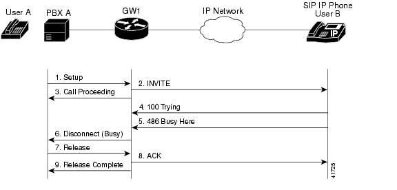
Step
|
Action
|
Description
|
1.
|
Setup—PBX A to Gateway 1
|
Call setup is initiated between PBX A and Gateway 1. Setup includes the standard transactions that take place as A attempts to call B.
|
2.
|
INVITE—Gateway 1 to Cisco SIP IP phone
|
Gateway 1 maps the SIP URL phone number to a dial peer. The dial peer includes the IP address and the port number of the SIP-enabled entity to contact. Gateway 1 sends a SIP INVITE request to the address it receives as the dial peer, which, in this scenario, is the IP phone. In the INVITE request:
•The IP address of the phone is inserted in the Request-URI field.
•PBX A is identified as the call session initiator in the From field.
•A unique numeric identifier is assigned to the call and is inserted in the Call-ID field.
•The transaction number within a single call leg is identified in the CSeq field.
•The media capability A is ready to receive is specified.
•The port on which the gateway is prepared to receive the RTP data is specified.
|
3.
|
Call Proceeding—Gateway 1 to PBX A
|
Gateway 1 sends a Call Proceeding message to PBX A to acknowledge the Call Setup request.
|
4.
|
100 Trying—Cisco SIP IP phone to Gateway 1
|
The phone sends a SIP 100 Trying response to Gateway 1. The response indicates that the INVITE request has been received.
|
5.
|
486 Busy Here—Cisco SIP IP phone to Gateway 1
|
The phone sends a SIP 486 Busy Here response to Gateway 1. The response is a client error response that indicates that B was successfully contacted but that B was not willing or was unable to take the call.
|
6.
|
Disconnect (Busy)—Gateway 1 to PBX A
|
Gateway 1 sends a Disconnect message to PBX A.
|
7.
|
Release—PBX A to Gateway 1
|
PBX A sends a Release message to Gateway 1.
|
8.
|
ACK—Gateway 1 to Cisco SIP IP phone
|
Gateway 1 sends a SIP ACK to the phone. The ACK confirms that A has received the 486 Busy Here response. The call session attempt terminates.
|
9.
|
Release Complete—Gateway 1 to PBX A
|
Gateway 1 sends a Release Complete message to PBX A, and the call session attempt terminates.
|
Called Number Does Not Answer
Figure B-19 illustrates the call flow in which User A initiates a call to User B, but User B does not answer.
Figure B-19 Called Number Does Not Answer
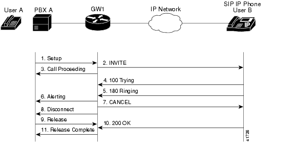
Step
|
Action
|
Description
|
1.
|
Setup—PBX A to Gateway 1
|
Call setup is initiated between PBX A and Gateway 1. Setup includes the standard transactions that take place as A attempts to call B.
|
2.
|
INVITE—Gateway 1 to Cisco SIP IP phone
|
Gateway 1 maps the SIP URL phone number to a dial peer. The dial peer includes the IP address and the port number of the SIP-enabled entity to contact. Gateway 1 sends a SIP INVITE request to the address it receives as the dial peer, which, in this scenario, is the IP phone. In the INVITE request:
•The IP address of the phone is inserted in the Request-URI field.
•PBX A is identified as the call session initiator in the From field.
•A unique numeric identifier is assigned to the call and is inserted in the Call-ID field.
•The transaction number within a single call leg is identified in the CSeq field.
•The media capability A is ready to receive is specified.
•The port on which the gateway is prepared to receive the RTP data is specified.
|
3.
|
Call Proceeding—Gateway 1 to PBX A
|
Gateway 1 sends a Call Proceeding message to PBX A to acknowledge the Call Setup request.
|
4.
|
100 Trying—Cisco SIP IP phone to Gateway 1
|
The phone sends a SIP 100 Trying response to Gateway 1. The response indicates that the INVITE request has been received.
|
5.
|
180 Ringing—Cisco SIP IP phone to Gateway 1
|
The phone sends a SIP 180 Ringing response to Gateway 1. The response indicates that the user is being alerted.
|
6.
|
Alerting—Gateway 1 to PBX A
|
Gateway 1 sends an Alert message to PBX A.
|
7.
|
CANCEL (Ring Timeout)—Gateway 1 to Cisco SIP IP phone
|
Because Gateway 1 did not return an appropriate response within the time allocated in the INVITE request, Gateway 1 sends a SIP CANCEL request to the gateway 2. A CANCEL request cancels a pending request with the same Call-ID, To, From, and CSeq header field values.
|
8.
|
Disconnect—Gateway 1 to PBX A
|
Gateway 1 sends a Disconnect message to PBX A.
|
9.
|
Release Complete—Gateway 1 to PBX A
|
Gateway 1 sends a Release Complete message to PBX A, and the call session attempt terminates.
|
10.
|
200 OK—Cisco SIP IP phone to Gateway 1
|
The phone sends a SIP 200 OK response to Gateway 1. The response confirms that A has received the 486 Busy Here response. The call session attempt terminates.
|
11.
|
Release Complete—Gateway 1 to PBX A
|
Gateway 1 sends a Release Complete message to PBX A, and the call session terminates.
|
Client, Server, or Global Error
Figure B-20 illustrates an unsuccessful call in which User A initiates a call to User B and receives a class 4xx, 5xx, or 6xx response.
Figure B-20 Client, Server, or Global Error
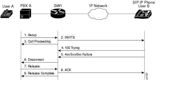
Step
|
Action
|
Description
|
1.
|
Setup—PBX A to Gateway 1
|
Call setup is initiated between PBX A and Gateway 1. Setup includes the standard transactions that take place as A attempts to call B.
|
2.
|
INVITE—Gateway 1 to Cisco SIP IP phone
|
Gateway 1 maps the SIP URL phone number to a dial peer. The dial peer includes the IP address and the port number of the SIP-enabled entity to contact. Gateway 1 sends a SIP INVITE request to the address it receives as the dial peer, which, in this scenario, is the IP phone. In the INVITE request:
•The IP address of the phone is inserted in the Request-URI field.
•PBX A is identified as the call session initiator in the From field.
•A unique numeric identifier is assigned to the call and is inserted in the Call-ID field.
•The transaction number within a single call leg is identified in the CSeq field.
•The media capability A is ready to receive is specified.
•The port on which the gateway is prepared to receive the RTP data is specified.
|
3.
|
Call Proceeding—Gateway 1 to PBX A
|
Gateway 1 sends a Call Proceeding message to PBX A to acknowledge the call setup request.
|
4.
|
100 Trying—Cisco SIP IP phone to Gateway 1
|
The phone sends a SIP 100 Trying response to Gateway 1. The response indicates that the INVITE request has been received.
|
5.
|
4xx/5xx/6xx Failure—Cisco SIP IP phone to Gateway 1
|
The phone sends a class 4xx, 5xx, or class 6xx failure response to the gateway 1. Depending on which class the failure response is, the call actions differ.
If the phone sends a class 4xx failure response (a definite failure response that is a client error), the request will not be retried without modification.
If the phone sends a class 5xx failure response (an indefinite failure that is a server error), the request is not terminated, but rather other possible locations are tried.
If the phone sends a class 6xx failure response (a global error), the search for B terminates because the 6xx response indicates that a server has definite information about B, but not for the particular instance indicated in the Request-URI field. Therefore, all further searches for this user will fail.
|
6.
|
Disconnect—Gateway 1 to PBX A
|
Gateway 1 sends a Release message to PBX A.
|
7.
|
Release—PBX A to Gateway 1
|
PBX A sends a Release message to Gateway 1.
|
8.
|
ACK—Gateway 1 to Cisco SIP IP phone
|
Gateway 1 sends a SIP ACK to the phone. The ACK confirms that PBX A has received the 486 Busy Here response. The call session attempt terminates.
|
9.
|
Release Complete—Gateway 1 to PBX A
|
Gateway 1 sends a Release Complete message to PBX A, and the call session attempt terminates.
|
Cisco SIP IP Phone to Cisco SIP IP Phone in a SIP Network
The following scenarios are Cisco SIP IP phone to Cisco SIP IP phone:
• Called Number Is Busy
• Called Number Does Not Answer
• Authentication Error
Called Number Is Busy
Figure B-21 illustrates an unsuccessful call in which User A initiates a call to User B, but User B is on the phone and is unable or unwilling to take another call.
Figure B-21 Called Number Is Busy
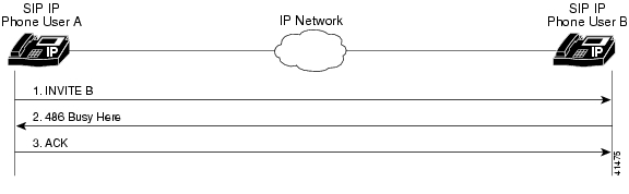
Step
|
Action
|
Description
|
1.
|
INVITE—Phone A to Phone B
|
Phone A sends a SIP INVITE request to Phone B. The request is an invitation to User B to participate in a call session. In the INVITE request:
•The phone number of User B is inserted in the Request-URI field in the form of a SIP URL. The SIP URL identifies the address of B and takes a form similar to an e-mail address (user@host, where user is the telephone number and host is either a domain name or a numeric network address). For example, the Request-URI field in the INVITE request to B appears as "INVITE sip:555-0199@companyb.com; user=phone." The "user=phone" parameter distinquishes that the Request-URI address is a telephone number rather than a username.
•Phone A is identified as the call session initiator in the From field.
•A unique numeric identifier is assigned to the call and is inserted in the Call-ID field.
•The transaction number within a single call leg is identified in the CSeq field.
•The media capability A is ready to receive is specified.
|
2.
|
486 Busy Here—Phone B to Phone A
|
Phone B sends a 486 Busy Here message to the Phone A. The message indicates that Phone B is in use and the user is not willing or able to take additional calls.
|
3.
|
ACK—Phone A to Phone B
|
Phone A sends a SIP ACK to the Phone B. The ACK confirms that Phone A has received the 486 Busy Here response from Phone B.
|
Called Number Does Not Answer
Figure B-22 illustrates an unsuccessful call in which User A initiates a call to User B, but User B does not answer.
Figure B-22 Called Number Does Not Answer
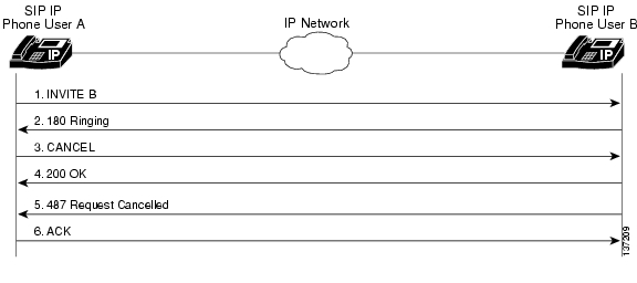
Step
|
Action
|
Description
|
1.
|
INVITE—Phone A to Phone B
|
Phone A sends a SIP INVITE request to Phone B. The request is an invitation to User B to participate in a call session. In the INVITE request:
•The phone number of B is inserted in the Request-URI field in the form of a SIP URL. The SIP URL identifies the address of B and takes a form similar to an e-mail address (user@host, where user is the telephone number and host is either a domain name or a numeric network address). For example, the Request-URI field in the INVITE request to B appears as "INVITE sip:555-0199@companyb.com; user=phone." The "user=phone" parameter distinquishes that the Request-URI address is a telephone number rather than a username.
•Phone A is identified as the call session initiator in the From field.
•A unique numeric identifier is assigned to the call and is inserted in the Call-ID field.
•The transaction number within a single call leg is identified in the CSeq field.
•The media capability A is ready to receive is specified.
|
2.
|
180 Ringing—Phone B to Phone A
|
Phone B sends a SIP 180 Ringing response to Phone A.
|
3.
|
CANCEL (Ring Timeout)—Phone A to Phone B
|
Phone A sends a CANCEL request to Phone B to cancel the invitation.
|
4.
|
200 OK—Phone B to Phone A
|
Phone B sends a SIP 200 OK response to Phone A. The response confirms receipt of the cancellation request.
|
5.
|
Request Cancelled—Phone B to Phone A
|
Phone B sends a SIP 487 Request Cancelled response to Phone A. This response confirms the cancellation of the call.
|
6.
|
ACK—Phone A to Phone B
|
Phone A sends a SIP ACK to Phone B acknowledging the 487 response.
|
Authentication Error
Figure B-23 illustrates an unsuccessful call in which User A initiates a call to User B but is prompted for authentication credentials by the proxy server. User A's SIP IP phone then reinitiates the call with a SIP INVITE request that includes authentication credentials.
Figure B-23 Authentication Error
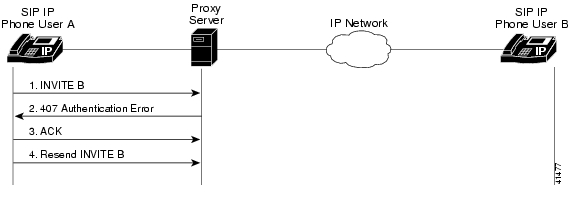
Step
|
Action
|
Description
|
1.
|
INVITE—Phone A to SIP proxy server
|
Phone A sends a SIP INVITE request to the SIP proxy server. The request is an invitation to B to participate in a call session. In the INVITE request:
•The phone number of B is inserted in the Request-URI field in the form of a SIP URL. The SIP URL identifies the address of User B and takes a form similar to an e-mail address (user@host, where user is the telephone number and host is either a domain name or a numeric network address). For example, the Request-URI field in the INVITE request to User B appears as "INVITE sip:555-0199@companyb.com; user=phone." The "user=phone" parameter distinquishes that the Request-URI address is a telephone number rather than a username.
•Phone A is identified as the call session initiator in the From field.
•A unique numeric identifier is assigned to the call and is inserted in the Call-ID field.
•The transaction number within a single call leg is identified in the CSeq field.
•The media capability User A is ready to receive is specified.
|
2.
|
407 Authentication Error—SIP proxy server to Phone A
|
The SIP proxy server sends a SIP 407 Authentication Error response to Phone A.
|
3.
|
ACK—Phone A to SIP proxy server
|
Phone A sends a SIP ACK to the SIP proxy server acknowledging the 407 error message.
|
4.
|
Resend INVITE—Cisco SIP IP phone A to SIP proxy server
|
Phone A resends a SIP INVITE to the SIP proxy server with authentication credentials.
|

