cc/td/doc/product/voice/c_ipphon/english/ipp7960/addprot/sip/admin
hometocprevnextglossaryfeedbacksearchhelp
PDF

Table Of Contents

Installing Cisco IP 7960G/7940G Phone Hardware on the Desktop or Wall

Placing the Phone on the Desktop

Installing the Phone on the Wall

Cabling the Phone Ports

Using the Phone with a Cisco Catalyst Switch

Connecting the Phone to Power

Where to Go Next


Installing Cisco IP 7960G/7940G Phone Hardware on the Desktop or Wall


This chapter explains how to install the Cisco IP 7960G/7940G phone on the desktop or how to mount it to the wall. It provides information on the following:

Placing the Phone on the Desktop

Installing the Phone on the Wall

Cabling the Phone Ports

Using the Phone with a Cisco Catalyst Switch

Connecting the Phone to Power

Where to Go Next

Placing the Phone on the Desktop

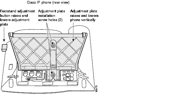
You can place the phone on the desktop or on the wall. The Cisco IP phone includes an adjustable footstand. When placing the phone on a desktop surface, you can adjust the tilt height to several different angles in 7.5-degree increments from flat to 60 degrees.

Installing the Phone on the Wall

Mount the Cisco IP 7960G/7940G phone on the wall by using the footstand as a mounting bracket or by using the optional locking bracket. To use the optional locking bracket, refer to the Installing the Wall Mount Kit for the Cisco IP Phone document on Cisco.com.


Note Mounting the Cisco IP 7960G/7940G phone on the wall requires some tools and equipment that are not provided. The tools and parts required for a typical Cisco IP phone installation are a screwdriver and screws to secure the phone to the wall.


Procedure


Step 1 Push in the footstand adjustment knob.

Step 2 Adjust the footstand so that it is flat against the back of the phone, as shown in Figure 2-1.

Figure 2-1 Adjusting the Footstand

Step 3 Modify the handset rest so that the handset remains on the earpiece rest when the phone is vertical.

a. Remove the handset from the earpiece rest.

b. Locate the tab (handset wall hook) at the base of the earpiece rest.

c. Slide this tab out, rotate it 180 degrees, and reinsert it.

d. Place the handset on the earpiece rest.

Step 4 Insert two screws into a wall stud, matching them to the two screw holes on the back of the footstand. The screw holes fit standard phone jack mounts.

Step 5 Hang the phone on the wall.


Cabling the Phone Ports

The Cisco MGCP IP phone has several ports on the back of the phone, shown in Figure 1-3 on page 1-5. Plug the appropriate equipment into the appropriate port.


Caution Consider use of an uninterruptible power supply (UPS). Without one, when you use either a local transformer or inline power on the LAN, the phone is inoperable during a power outage. This affects your ability to make emergency calls: 911 in USA and Canada, 999 in the UK, and 112 in mainland Europe.


Note Use of a headset does not require an amplifier. However, it does require a coil cord to connect the headset to the headset port. For information on ordering compatible headsets and coil cords, refer to http://cisco.getheadsets.com or http://vxicorp.com/cisco.


Note Do not connect the phone to power or the network at this time. Doing so causes the phone to initialize and download firmware and configuration files. Initialization and modification of the configuration files are described in the Chapter 3, "Initializing Cisco SIP IP Phones."


Using the Phone with a Cisco Catalyst Switch

To function in the SIP telephony network, the Cisco IP 7960G/7940G phone must be connected to a networking device, such as a Cisco Catalyst switch, to obtain network connectivity. The Cisco IP 7960G/7940G phone has an internal Ethernet switch, which enables it to switch traffic that comes from the phone, access port, and network port.

If a computer is connected to the access port, packets that travel to and from the computer and to and from the phone share the same physical link to the switch and the same port on the switch. This configuration has the following implications for the VLAN configuration on the network:

The current VLANs might be configured on an IP subnet basis, and additional IP addresses might not be available to assign the phone to the same subnet as other devices (PC) connected to the same port.

Data traffic that is present on the VLAN that supports phones might reduce the quality of VoIP traffic.

You can resolve these issues by isolating the voice traffic onto a separate VLAN on each of the ports connected to a phone. The switch port configured for connecting a phone would have separate VLANs configured for carrying the following traffic:

Voice traffic to and from the Cisco IP 7960G/7940G phone (auxiliary VLAN).

Data traffic to and from the PC connected to the switch through the access port of the Cisco IP 7960G/7940G phone (native VLAN).

Isolating the phones on a separate, auxiliary VLAN increases the quality of the voice traffic and allows a large number of phones to be added to an existing network where there are not enough IP addresses.

For redundancy, you can use the AC adapter even if you are using inline power from the Cisco Catalyst switches. The Cisco IP 7960G/7940G phone can share the power load being used from the inline power and external power source. If either the inline power or the external power goes down, the phone can switch entirely to the other power source.

To use this redundancy feature you must set the inline power mode to "auto" on the Cisco Catalyst switch. Next, connect the Cisco IP 7960G/7940G phone to the network without connecting it to an external power source. After the phone powers up, connect the external power supply to the phone.

For more information, refer to the documentation included with the Cisco Catalyst switch.

Connecting the Phone to Power


Warning Read the installation instructions before you connect the system to its power source.


Waarschuwing Raadpleeg de installatie-aanwijzingen voordat u het systeem met de voeding verbindt.

Varoitus Lue asennusohjeet ennen järjestelmän yhdistämistä virtalähteeseen.

Attention Avant de brancher le système sur la source d'alimentation, consulter les directives d'installation.

Warnung Lesen Sie die Installationsanweisungen, bevor Sie das System an die Stromquelle anschließen.

Avvertenza Consultare le istruzioni di installazione prima di collegare il sistema all'alimentatore.

Advarsel Les installasjonsinstruksjonene før systemet kobles til strømkilden.

Aviso Leia as instruções de instalação antes de ligar o sistema à sua fonte de energia.

¡Advertencia! Ver las instrucciones de instalación antes de conectar el sistema a la red de alimentación.

Varning! Läs installationsanvisningarna innan du kopplar systemet till dess strömförsörjningsenhet.


Caution When you connect the phone to power, the phone automatically begins startup and initialization. Use this section to determine how you will power your phones. Do not connect the phones to power, though, until you address the prerequisites and follow the configuration instructions in Chapter 3, "Initializing Cisco SIP IP Phones."

You can connect the Cisco IP phone to the following power sources:

External power source—Optional AC adapter and power cord for connecting to a standard wall receptacle.

WS-X6348-RJ45V 10/100 switching module—Provides inline power to the phone when connected to a Cisco Catalyst 3500, 4000, or 6000 family 10/100BASE-TX switching module. This module sends power on pins 1 and 2, and 3 and 6.

WS-PWR-PANEL—Power patch panel provides power to the phone, which allows the phone to be connected to existing Cisco Catalyst 4000, 5000, and 6000 family 10/100BASE-TX switching modules. This module sends power on pins 4, 5, 7, and 8.

WS-X4148-RJ45V—48-port 10/100 Ethernet with inline power module for the Cisco Catalyst 4006 switch.

WS-X4095-PEM—VoIP DC Power Entry module for the Cisco Catalyst 4006 switch.

WS-X4608-2PSU and WS-X4608—External -48VDC power shelf common equipment for the Cisco Catalyst 4006 with two AC-to-DC power supply units (PSUs) and one empty bay for redundant option, and the 110-V 15-A AC-to-48VDC PSU redundant option for the power shelf.

WS-C3524-PWR-XL-EN—Cisco Catalyst 3524-PWR XL switch.


NoteOnly the network port (labeled 10/100 SW) supports inline power from the Cisco Catalyst switches.

If you are using a Cisco Catalyst switch to provide power, see the "Using the Phone with a Cisco Catalyst Switch" section.


Where to Go Next

See Chapter 3, "Initializing Cisco SIP IP Phones," for information on installing firmware, customizing configuration files, and connecting the phone to power sources and the network.

See Chapter 4, "Managing Cisco SIP IP Phones," for information on upgrading firmware and performing other management tasks.

See Chapter 5, "Monitoring Cisco SIP IP Phones," for information on debugging and on viewing network statistics.


hometocprevnextglossaryfeedbacksearchhelp

Posted: Tue Sep 26 15:33:40 PDT 2006
All contents are Copyright © 1992--2006 Cisco Systems, Inc. All rights reserved.
Important Notices and Privacy Statement.