|
|

Table Of Contents
New Information for This Release
Cisco Unified IP Phone 7960G and 7940G Overview
Session Initiation Protocol Overview
Dial-Plan and Messaging Support
Supported Languages and Character Set
Product Overview
This chapter provides the following information about the Cisco Unified IP Phone 7960G and 7940G:
•
New Information for This Release
•
•
•
•
New Information for This Release
The following changes have been made and the following features have been added to release 8.0:
•
•
http://www.cisco.com/en/US/partner/products/sw/voicesw/ps2156/prod_release_notes_list.html
Cisco Unified IP Phone 7960G and 7940G Overview
Cisco Unified IP Phone 7960G and 7940G models are full-featured telephones that can be plugged directly into a SIP network and can be used very much like a standard PBX telephone. Phone terminals can attach to the existing data network infrastructure, using 10BASE-T and 100BASE-T interfaces on an Ethernet switch.
When used with a voice-capable Ethernet switch, one that understands type of service (ToS) bits and can prioritize VoIP traffic, the phones eliminate the need for a traditional proprietary telephone set and key system or PBX.
The Cisco Unified IP Phone 7960G and 7940G also supports an adjustable ring tone, a hearing-aid compatible handset, and a headset.
The Cisco Unified IP Phone 7960G and 7940G complies with RFC 3261, as described in Appendix A, "Compliance with RFC 3261."
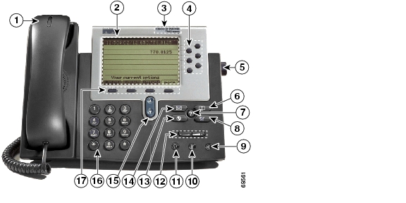
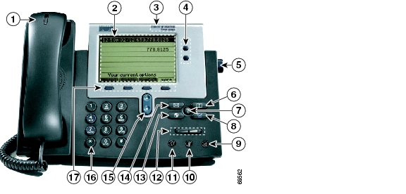
See Figure 1-1 and Figure 1-2 to identify the buttons and hardware on your Cisco IP phone.
Figure 1-1 Cisco IP Phone 7960G
Figure 1-2 Cisco IP Phone 7940G
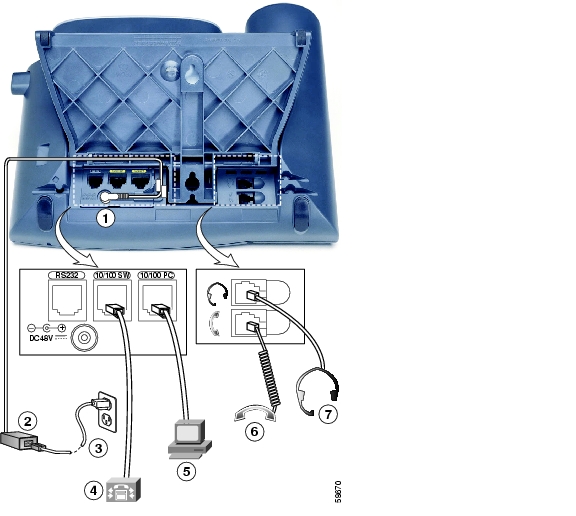
Figure 1-3 shows the connections on the back of the Cisco IP phone. Cisco Unified IP Phone 7960G/7940G models have the same hardware configuration.
Figure 1-3 Cisco IP Phone Cable Connections
AC/DC adapter port (DC48V) for power connector. For redundancy, you can use the AC adapter even if you are using inline power from Cisco Catalyst switches. The Cisco Unified IP Phone 7960G and 7940G can share the power being used from the inline power and external power source. If either the inline power or the external power goes down, the phone can switch entirely to the other power source.
Power supply with AC plug.
Power cable with wall socket plug for connecting to power.
Network port (10 and 100 SW) RJ-45 to connect the phone to the network supporting 10- or 100-Mbps half- or full-duplex Ethernet connections to external devises. You can use either Category 3 or Category 5 cabling for 10-Mpbs connections, but use Category 5 for 100-Mbps connections. To avoid collisions, use full-duplex mode. You must use a straight-through cable on this port. The phone can also obtain inline power from the Cisco Catalyst switch over this connection.
Access port (10 and 100 PC) RJ-45 to connect a network device, such as a computer, to the phone supporting from 10- to 100- Mbps half- or full-duplex Ethernet connections to external devices. You can use either Category 3 or Category 5 cabling for 10-Mpbs connections, but use Category 5 for 100-Mbps connections. To avoid collisions, use full-duplex mode. You must use a straight-through cable on this port.
Handset port for connecting a handset.
Headset port for connecting a headset. Enables the headset. The phone supports a four- or six-wire headset jack. The volume and mute controls also adjust volume to the earpiece and mute the speech path of the headset. The headset activation key is located on the front of the Cisco Unified IP Phone 7960G and 7940G.
The phone supports the following Plantronics four- or six-wire headsets: Tristar Monaural, Encore Monaural H91, and Encore Binaural H101.
When a headset is used, an amplifier is not required. However, a coil cord is required to connect the headset to the headset port on the back of your Cisco Unified IP Phone 7960G and 7940G. For information on ordering compatible headsets and coil cords for the Cisco Unified IP Phone 7960G and 7940G, go to http://cisco.plantronics.com or http://www.vxicorp.com/cisco.
Session Initiation Protocol Overview
Session Initiation Protocol (SIP) is the Internet Engineering Task Force (IETF) standard for multimedia conferencing over IP. SIP is an ASCII-based, application-layer control protocol (defined in RFC 3261) that can be used to establish, maintain, and terminate calls between two or more endpoints.
Like other VoIP protocols, SIP is designed to address the functions of signaling and session management within a packet telephony network. Signaling allows call information to be carried across network boundaries. Session management provides the ability to control the attributes of an end-to-end call.
SIP Capabilities
SIP provides the capabilities to do the following:
•
•
•
•
•
Conferences can consist of two or more parties and can be established using multicast or multiple unicast sessions.
Note
SIP Components
SIP is a peer-to-peer protocol. The peers in a session are called user agents (UAs). A user agent can function in one of the following roles:
•
•
Typically, a SIP endpoint is capable of functioning as both a UAC and a UAS, but functions only as one or the other per transaction. Whether the endpoint functions as a UAC or a UAS depends on the UA that initiated the request.
From an architecture standpoint, the physical components of a SIP network can also be grouped into two categories: clients and servers. Figure 1-4 illustrates the architecture of a SIP network.
Note
Figure 1-4 SIP Architecture
SIP Clients
SIP clients include the following:
•
Phones act as either a UAS or a UAC. Softphones (PCs that have phone capabilities installed) and Cisco SIP IP phones can initiate SIP requests and respond to requests.
•
Gateways provide call control. Gateways provide many services, the most common being a translation function between SIP conferencing endpoints and other terminal types. This function includes translation between transmission formats and between communications procedures. In addition, the gateway also translates between audio and video codecs and performs call setup and clearing on both the LAN side and the switched-circuit side.
SIP Servers
SIP servers include the following:
•
A proxy server receives SIP client messages and forwards them to the next SIP server in the network. Proxy servers can provide functions such as authentication, authorization, network access control, routing, reliable request retransmission, and security.
•
A redirect server receives SIP requests, strips out the address in the request, checks its address tables for any other addresses that may be mapped to the one in the request, and then returns the results of the address mapping to the client. Basically, redirect servers provide the client with information about the next hop or hops that a message should take, and then the client contacts the next-hop server or UAS directly. Location services are often included with redirect servers and provide contact information and address bindings for called parties.
•
A registrar server processes requests from UACs for registration of their current location. Registrar servers are often colocated with a redirect or proxy server.
BTXML Support
The Cisco SIP IP phone supports Basic Telephony eXtensible Markup Language. BTXML defines XML elements for controlling the user interface of an IP telephone. It describes what information is displayed on the screen and how to provide input using softkeys and hard keys. User-interface control is internal to the phone; there is no external BTXML user interface control.
Cisco IP Phone Services
The Cisco SIP IP phone supports Cisco IP Phone Services that you configure to provide data such as stock quotes, calendars, and directory lookups. Phone users access this information using phone buttons such as the Services or Directories buttons. See Chapter 4, "Managing Cisco SIP IP Phones," for information about configuring these cards.
Note
For more information about using XML on your Cisco SIP IP phone, refer to the following:
•
http://www.hotdispatch.com/cisco-ip-telephony•
http://www.cisco.com/pcgi-bin/dev_support/access_level/product_support•
Network Capabilities
The Cisco Unified IP Phone 7960G and 7940G supports the following networking capabilities:
•
Allows you to use Telnet to connect directly to the phone to debug and troubleshoot the phone.
•
Allows you to ping from the phone to see if it is operational and assess how long the response time from the phone is.
•
Allows you to see the path that the signal traverses in the route to its desired destination.
Configuration Features
With the Cisco Unified IP Phone 7960G and 7940G, you can do the following:
•
•
•
•
•
•
•
•
•
•
•
•
•
•
Signaling Support
The following signaling and transport features are supported:
•
•
•
Dial-Plan and Messaging Support
The Cisco SIP IP phone supports a dial plan that enables automatic dialing and generation of a selectable secondary dial tone. The Cisco SIP IP phone also supports the following:
•
Each time a call is successfully made or received, the number is stored in a local directory that is maintained on the phone. The maximum number of entries is 32. Entries are aged out according to usage and age. The oldest entry that has been called the least number of times is overwritten first. This feature cannot be changed by the phone user; however, up to 20 entries can be "locked" (using the Locked softkey) so that they will never be deleted.
•
When a caller leaves a voice message, a light indicates that a new voice message is in your mailbox. If you listen to the message but do not save or delete the message, the light remains on. If you listen to the new message and save or delete it, the light goes off. The message waiting indicator is controlled by the voice-mail server. The indication is saved over a phone upgrade or reboot.
•
In previous versions of the dial plan, the "*" and "#" characters were not matched if specified as dialed digits. The "*" character was a wildcard equal to "match one or more characters." The "#" character was interpreted as "dial immediately." Support was added for the "*" character by adding "\" as an escape character and the "#" character as a digit in the dial plan. Backward compatibility for the "#" and "*" characters is supported.
•
If the INVITE message from the server contains an Alert-Info header, distinctive ringing is invoked. The format of the header is "Alert-info: x." The value of "x" can be any number. This header is received only by the phone and is not generated by the phone.
Distinctive ringing is supported when the phone is idle or during a call. In the idle mode, the phone rings with a different cadence. The selected ringing type plays twice with a short pause in between. In call-waiting mode, two short beeps are generated instead of one long beep.
•
In earlier releases, specifying a comma (,) in the dial plan caused the phone to play the default secondary dial tone. With this release, specific user-specified tones can play. You can specify up to three different secondary dial tones in a single dial-plan match template. Tones play in the order in which they are listed.
•
The parameter is selectable from the Settings > Call Preferences menu. When the parameter is enabled, the phone rings if the handset is placed on-hook and there is also a call on hold.
•
•
•
Routing and Proxy Support
The Cisco SIP IP phone supports the following routing and proxy features:
•
The route attribute in the dial-plan template file can be used to indicate to which proxy—default, emergency, fully qualified domain name (FQDN)—the call should be initially routed. For example, to configure an emergency proxy, specify the value of the route attribute as "emergency."
•
When the primary proxy does not respond to the INVITE message sent by the phone after the configured number of retries, the phone sends the INVITE to the backup proxy. This is independent from the proxy defined in the route attribute in the dial-plan template used.
The Cisco SIP IP phone attempts to register with the backup proxy. All interactions with the backup proxy, such as authentication challenges, are treated the same as the interactions with the primary proxy. The backup proxy is used only with new INVITE messages that fail to communicate with the primary proxy. Once the backup proxy is used, it is active for the duration of the call.
The location of the backup SIP proxy can be defined as an IP address in the default configuration file.
•
An optional emergency SIP proxy can be configured with the route attribute of the template tag in the dial-plan template file. When an emergency SIP proxy is configured and a call is initiated, the phone generates an INVITE message to the address specified in the proxy_emergency parameter. The emergency proxy is used for the entire call.
The location of the emergency proxy can be defined as an IP address in the default configuration file.
•
The Domain Name Server (DNS) SRV query is used to locate servers for a given service. SIP on Cisco IP phones uses a DNS SRV query to determine the IP address of the SIP proxy or redirect server. The query string generated is in compliance with RFC 2782 and prepends the protocol label with an underscore (_), as in "_protocol._transport." The addition of the underscore reduces the risk of the same name being used for unrelated purposes.
In compliance with RFC 2782 and the draft-ietf-sip-srv-01 specification, the system can remember multiple IP addresses and use them properly. In the draft-ietf-sip-srv-01 specification, it is assumed that all proxies returned for the SRV record are equivalent such that the phone can register with any of the proxies and initiate a call using any other proxy.
•
Enable or disable NAT with the nat_enable parameter. You can configure the address of the NAT or firewall server using the nat_address parameter.
You can configure the IP address and port number of the outbound proxy server. When outbound proxy is enabled, all SIP requests are sent to the outbound proxy server instead of to the proxyN_address. All responses continue to reconcile the normal Using processing rules. The media stream is not routed through the outbound proxy.
You can enable or disable NAT and outbound proxy modes independently. The received= tag is added to the Via header of all responses if there is no received= tag in the uppermost Via header and the source IP address is different from the IP address in the uppermost Via header. Responses are sent back to the source under the following conditions:
–
–
Note
Supported Languages and Character Set
The Cisco SIP IP phone supports the ISO 8859-1 Latin1 characters and the following languages: French (fr), Spanish (es), Catalan (ca), Basque (eu), Portuguese (pt), Italian (it), Albanian (sq), Rhaeto-Romanic (rm), Dutch (nl), German (de), Danish (da), Swedish (sv), Norwegian (no), Finnish (fi), Faroese (fo), Icelandic (is), Irish (ga), Scottish (gd), English (en), Afrikaans (af), and Swahili (sw).
It does not support the following languages: Zulu (zu) and other Bantu languages that use Latin Extended-B letters; Arabic in North Africa; and Guarani (gn), which is missing the letters G, E, I, U, and Y with tildes (~).
Note
You can use ISO 8859-1 Latin1 characters in the following areas:
•
•
•
Note
Supported Protocols
The Cisco SIP IP phone supports the protocols listed in Table 1-1.
Where to Go Next
Use the following information to determine where to go next in this guide:
•
•
•
•
![]()
![]()
![]()
![]()
![]()
![]()
![]()
![]()
Posted: Tue Apr 24 10:59:00 PDT 2007
All contents are Copyright © 1992--2007 Cisco Systems, Inc. All rights reserved.
Important Notices and Privacy Statement.