|
|

Table Of Contents
Calling Name and Number Feature
Cisco CallManager Configuration
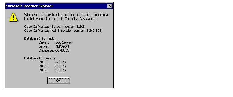
Cisco CallManager Software Release
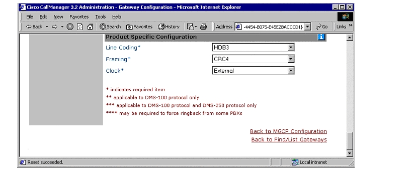
Cisco 2621XM Gateway Configuration
Application Note
NEC 2400 ICS Rel J 5.8 PBX with CallManager using 2621XM-E1 PRI as MGCP Gateway
This application note illustrates connectivity for NEC 2400 ICS Rel J 5.8 PBX with CallManager using 2621XM-E1 PRI as MGCP Gateway.
Introduction
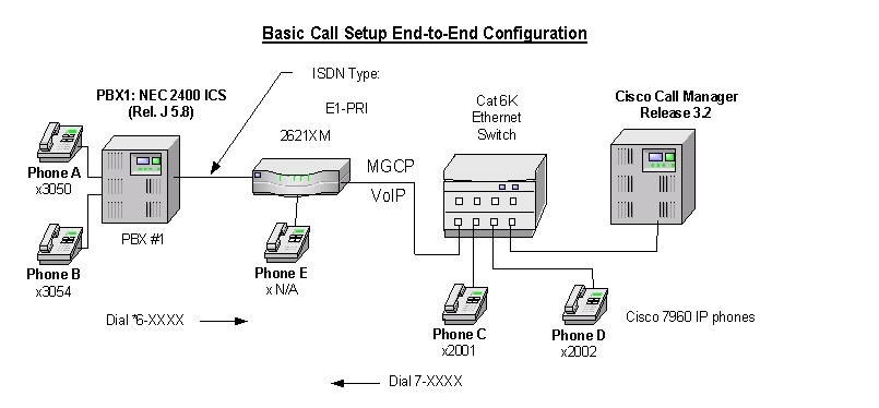
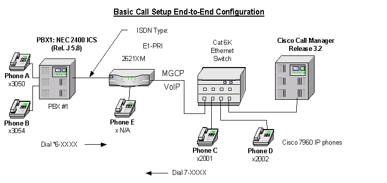
The network topology diagram presented in Figure 1 illustrates the test set-up for end-to-end interoperability with the Cisco CallManager connected to the PBX via 2621XM-E1 PRI link as MGCP Gateway.
Key test environment parameters:
•
Connectivity is achieved by using the PRI EURO protocol type on the MGCP gateway and NEC/ETSI switch type on the NEC 2400 PBX. Though the NEC 2400 can be configured as either NETWORK (Master) or USER (Slave) side, this is not recommended and the NEC TAC center will not resolve a case presented with NEC set as NETWORK side.
•
•
Network Diagram
Figure 1
Network Test Topology
Limitations
Calling Name and Number Feature
Calling Name delivery and presentation feature are not supported by the NEC 2400 ICS PBX.
When calling from Cisco 7960 IP phone to NEC digital phone, both phones display the Number after the call is answered as expected.
When calling from NEC digital phone to Cisco 7960 IP phone, the Cisco IP phone displays Calling Number when the call is answered. NEC phone however does NOT get updated when the call is answered. It displays the numbers being dialed instead (i.e. Access Code + extension number). It was verified using an ISDN protocol analyzer that the CCM was not sending "Connected Number" information in the CONNECT message back to PBX.
System Components
Hardware Requirements
Cisco Hardware:
•
•
•
NEC 2400 ICS PBX:
•
Software Requirements
•
•
Feature
Key features supported:
•
Key features not supported:
•
•
Configuration
Sequence of configuration tasks:
3.
NEC 2400 ICS Configuration
The NEC requires a substantial amount of programming and circuit card switch settings to properly install E1 PRI. It is beyond the scope of this document to provide the entire configuration, therefore the NEC information below is mostly helpful for NEC techs. If further assistance is required, the entire configuration of our lab PBX can be found in EDCS document # EDCS-207455. The EDCS document provides the programs required for E1 ISDN circuit setup, all the switch settings for all cards on our Lab NEC and fairly complete configuration listings (List Ups).
Note:
Configure in the following sequence:
1.
2.
Route (ARTD) Configuration
Below are the Route settings found in ARTD. Route 12 is the B channel and Route 13 is the D channel. Please refer to EDCS document # EDCS-207455 for complete details for configuration.
[LRTD] CISCO TEST FACILITY 02/05/10 PAGE: 5* ROUTE CLASS DATA LIST *------- R O U T E N U M B E R -------CDN FUNCTION 11 12 13 14 151 OSGS 7 0 0 0 02 ONSG 3 2 0 2 23 ISGS 7 0 0 0 04 INSG 3 2 0 2 25 TF 3 3 3 3 36 TCL 4 4 4 4 47 L/T 1 1 1 1 18 RLP 2 2 0 2 09 TQ 0 0 0 0 010 SMDR 0 1 1 1 111 TD 0 0 0 0 012 DR 0 0 0 0 013 AC 1 1 0 1 014 TNT 0 0 0 0 015 LSG 5 12 13 12 1316 SMDR2 0 0 0 0 017 H/M 0 0 0 0 018 MC 0 0 0 0 019 ANI 0 1 1 1 020 D 0 0 0 0 021 MSB 0 0 0 0 022 MSW 0 0 0 0 023 TR 0 0 0 0 024 OC 0 0 0 0 025 R/L 0 0 0 0 026 RVSD 0 0 0 0 027 TL 0 0 0 0 028 ANS 0 1 1 1 129 TELP 0 0 0 0 030 PAD 0 4 7 4 731 OGRL 0 1 1 1 132 ICRL 0 1 1 1 133 HD 0 0 0 0 034 GUARD 0 1 1 1 135 WINK 0 0 0 0 036 VAD 0 0 0 0 037 CLD 0 0 0 0 038 FA 0 0 0 0 0[LRTD] CISCO TEST FACILITY 02/05/10 PAGE: 6* ROUTE CLASS DATA LIST *------- R O U T E N U M B E R -------CDN FUNCTION 11 12 13 14 1539 BC 0 0 0 0 040 TCM 0 0 0 0 041 TDMQ 0 0 0 0 042 TRSC 0 0 0 0 043 BT 0 1 0 1 144 PRV 0 0 0 0 045 A/D 0 1 1 1 146 CW 0 0 0 0 047 TPQ 0 0 0 0 048 BL 0 0 0 0 049 TRKS 0 1 1 0 050 DPLY 0 1 1 1 151 ACD 0 0 0 0 052 2W/4W 1 0 0 0 053 FAAT 0 0 0 0 054 GW 0 0 0 0 055 TCMA 0 0 0 0 056 SMDR3 0 0 0 0 057 HDT 0 0 0 0 058 CD 0 0 0 0 059 CCH 0 0 0 0 060 TC/EC 0 0 0 0 061 IRE 0 0 0 0 062 SCR 0 0 0 0 063 LYER1 0 1 1 1 164 NET 0 1 0 0 065 INT 0 4 4 4 466 DC 0 4 4 4 467 HKS 0 0 0 0 068 SCF 0 0 0 0 069 SMDR4 0 0 0 0 0Cisco CallManager Configuration
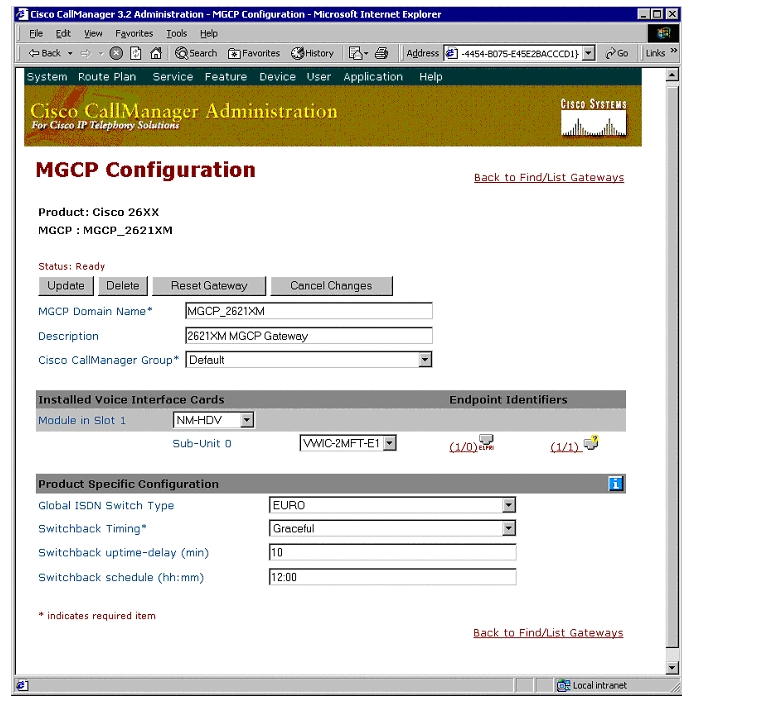
MGCP 2621XM-E1 Gateway Configuration
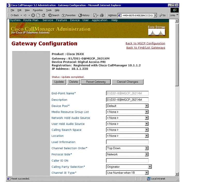
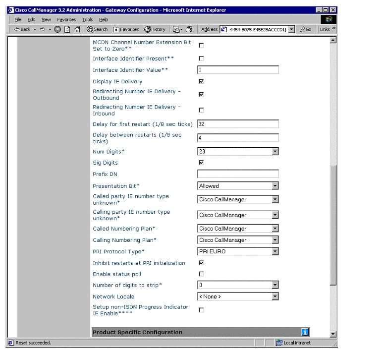
ISDN PRI Configuration
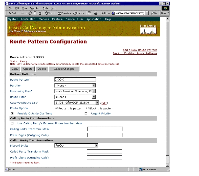
Route Pattern Configuration
Appendix A
Cisco CallManager Software Release
NEC 2400 ICS Software Release
Software Release:
VERSION ISSUE DATEJ 05.80 00/06/20 GenericF 01.00 96/04/26 Boot ROMCisco 2621XM Gateway Configuration
MGCP_2621XM#sh versionCisco Internetwork Operating System SoftwareIOS (tm) C2600 Software (C2600-JS-M), Version 12.2(10.7)T2, MAINTENANCE INTERIMSOFTWARETAC Support: http://www.cisco.com/tacCopyright (c) 1986-2002 by cisco Systems, Inc.Compiled Wed 05-Jun-02 12:20 by ccaiImage text-base: 0x8000809C, data-base: 0x819781E4ROM: System Bootstrap, Version 12.2(7r) [cmong 7r], RELEASE SOFTWARE (fc1)MGCP_2621XM uptime is 1 hour, 1 minuteSystem returned to ROM by reloadSystem image file is "flash:c2600-js-mz.122-10.7.T2"cisco 2621XM (MPC860P) processor (revision 0x100) with 124928K/6144K bytes of memory.Processor board ID JAD06110FE9 (4191950531)M860 processor: part number 5, mask 2Channelized E1, Version 1.0.Bridging software.X.25 software, Version 3.0.0.SuperLAT software (copyright 1990 by Meridian Technology Corp).TN3270 Emulation software.Primary Rate ISDN software, Version 1.1.2 FastEthernet/IEEE 802.3 interface(s)31 Serial network interface(s)2 Channelized E1/PRI port(s)32K bytes of non-volatile configuration memory.49152K bytes of processor board System flash (Read/Write)Configuration register is 0x2102MGCP_2621XM#MGCP_2621XM#sh diagSlot 0:C2621XM 2FE Mainboard Port adapter, 2 portsPort adapter is analyzedPort adapter insertion time unknownEEPROM contents at hardware discovery:Hardware Revision : 1.0PCB Serial Number : JAD06110FE9 (4191950531)Part Number : 73-7754-02RMA History : 00RMA Number : 0-0-0-0Board Revision : A0Deviation Number : 0-0EEPROM format version 4EEPROM contents (hex):0x00: 04 FF 40 03 6D 41 01 00 C1 18 4A 41 44 30 36 310x10: 31 30 46 45 39 20 28 34 31 39 31 39 35 30 35 330x20: 31 29 82 49 1E 4A 02 04 00 81 00 00 00 00 42 410x30: 30 80 00 00 00 00 FF FF FF FF FF FF FF FF FF FF0x40: FF FF FF FF FF FF FF FF FF FF FF FF FF FF FF FF0x50: FF FF FF FF FF FF FF FF FF FF FF FF FF FF FF FF0x60: FF FF FF FF FF FF FF FF FF FF FF FF FF FF FF FF0x70: FF FF FF FF FF FF FF FF FF FF FF FF FF FF FF FFSlot 1:High Density Voice Port adapterPort adapter is analyzedPort adapter insertion time unknownEEPROM contents at hardware discovery:Hardware Revision : 1.0Top Assy. Part Number : 800-03567-01Board Revision : A0Deviation Number : 0-0Fab Version : 02PCB Serial Number : JAB033906YARMA Test History : 00RMA Number : 0-0-0-0RMA History : 00EEPROM format version 4EEPROM contents (hex):0x00: 04 FF 40 00 CC 41 01 00 C0 46 03 20 00 0D EF 010x10: 42 41 30 80 00 00 00 00 02 02 C1 8B 4A 41 42 300x20: 33 33 39 30 36 59 41 03 00 81 00 00 00 00 04 000x30: FF FF FF FF FF FF FF FF FF FF FF FF FF FF FF FF0x40: FF FF FF FF FF FF FF FF FF FF FF FF FF FF FF FF0x50: FF FF FF FF FF FF FF FF FF FF FF FF FF FF FF FF0x60: FF FF FF FF FF FF FF FF FF FF FF FF FF FF FF FF0x70: FF FF FF FF FF FF FF FF FF FF FF FF FF FF FF FFVIC Slot 0:E1 (2 Port) Multi-Flex Trunk WAN Daughter CardHardware revision 1.0 Board revision B0Serial number 25028793 Part number 800-04479-02Test history 0x0 RMA number 00-00-00Connector type PCIEEPROM format version 1EEPROM contents (hex):0x20: 01 23 01 00 01 7D E8 B9 50 11 7F 02 00 00 00 000x30: 58 00 00 00 01 02 16 00 FF FF FF FF FF FF FF FFHDV firmware: Compiled Thu 27-Dec-01 13:17 by miriyalaHDV memory size 524280 heap free 171117MGCP_2621XM#MGCP_2621XM#sh controllers e1 1/0E1 1/0 is up.Applique type is Channelized E1 - balancedNo alarms detected.alarm-trigger is not setVersion info Firmware: 20020306, FPGA: 11Framing is CRC4, Line Code is HDB3, Clock Source is Line.Data in current interval (56 seconds elapsed):0 Line Code Violations, 0 Path Code Violations0 Slip Secs, 0 Fr Loss Secs, 0 Line Err Secs, 0 Degraded Mins0 Errored Secs, 0 Bursty Err Secs, 0 Severely Err Secs, 0 Unavail SecsMGCP_2621XM#MGCP_2621XM#sh runBuilding configuration...Current configuration : 1381 bytes!version 12.2service timestamps debug uptimeservice timestamps log uptimeno service password-encryption!hostname MGCP_2621XM!!voice-card 1!ip subnet-zero!!!isdn switch-type primary-net5!!voice call carrier capacity active!!!!!!!!!ccm-manager mgcpccm-manager music-on-holdccm-manager config server 10.1.1.2ccm-manager configfax interface-type fax-mailmta receive maximum-recipients 0!controller E1 1/0pri-group timeslots 1-31 service mgcp!controller E1 1/1!!!!interface FastEthernet0/0ip address 10.1.1.220 255.255.255.0duplex autospeed auto!interface FastEthernet0/1no ip addressshutdownduplex autospeed auto!interface Serial1/0:15no ip addressno logging event link-statusisdn switch-type primary-net5isdn protocol-emulate networkisdn incoming-voice voiceisdn bind-l3 ccm-managerno cdp enable!ip classlessno ip http serverip pim bidir-enable!!!!call rsvp-sync!voice-port 1/0:15!mgcpmgcp call-agent 10.1.1.2 service-type mgcp version 0.1mgcp dtmf-relay voip codec all mode out-of-bandmgcp modem passthrough voip mode nsemgcp package-capability rtp-packageno mgcp timer receive-rtcpmgcp sdp simple!mgcp profile default!dial-peer cor custom!!!dial-peer voice 1015 potsapplication mgcpappport 1/0:15!!line con 0line aux 0line vty 0 4loginline vty 5 15login!!endMGCP_2621XM#Test Configuration
Figure 2
Test Topology
As shown in the diagram above, an NEC 2400 ICS PBX was connected via an ISDN E1 PRI link to a Cisco 2621XM-E1 Gateway, which in turn, was connected to an Ethernet switch. The interoperability testing involved Layers 1, 2 and 3 on the ISDN PRI link between a Cisco 2621XM-E1 and the PBX.
Layers 2 & 3 (Q.921 and Q.931)
Layer 2 and 3 packet exchanges were monitored using an Acacia Clarinet protocol analyzer, bridged across the PRI link in high impedance mode.
Layer 2 Q.921 packets were monitored to ensure that each PBX/2621XM-E1 software configuration properly exchanged SABME/UA packets to initialize the ISDN link, and then RR packets were exchanged every 30 seconds.
Layer 3 Q.931 packets were monitored to ensure that the appropriate call setup/teardown packets were exchanged for each configuration, and that the SETUP packets contained the mandatory Information Elements with the necessary details, as well as optional IEs such as Calling Name and Number.
Telephone calls were made end-to-end in both directions through the Cisco 2621XM-E1 Gateway, and a check was made to ensure that there was an audio path in both directions for each call.
User/Network Settings
The Cisco 2621XM-E1 Gateway with ISDN protocol type setting of PRI EURO supports both protocol sides by selecting "Network/User" in the Protocol Side field when configuring the Gateway via CCM. The NEC 2400 ICS PBX supports "USER" protocol side.
Appendix B
Test Results
Testing was performed by Test Engineer(s): Samir Batio, June 12, 2002
Test Setup
Test configuration:
•
•
Table 2 Test Setup Switch and Gateway Settings
ETSI / User
PRI EURO / Network
Table 3 Basic Calls: (Enbloc Sending)
Yes
Yes
No
No1
No
Yes
Yes
No
Yes
No
1 CCM does not support sending "Connected Number" information in the connect message back to PBX.
2 The NEC 2400 with switch-type setting of ETSI for the PRI interface does not support "Calling Name" presentation feature.
1 NEC 2400 ICS PBX does not support Overlap sending/Receiving mode.
![]()
![]()
![]()
![]()
![]()
![]()
![]()
![]()
Posted: Thu Sep 6 13:37:01 PDT 2007
All contents are Copyright © 1992--2007 Cisco Systems, Inc. All rights reserved.
Important Notices and Privacy Statement.