|
|

 |
Warning Only trained and qualified personnel should be allowed to install or replace this equipment. |
 |
Warning This unit is intended for installation in restricted access areas. A restricted access area is where access can only be gained by service personnel through the use of a special tool, lock and key, or other means of security, and is controlled by the authority responsible for the location. |
Installation might require some tools and equipment that are not provided as standard equipment with the gateway. Following are the tools and parts required for a typical gateway installation:
 |
Note For more information on cable specifications, refer to the publication Cisco Modular Access Router Cabling Specifications on the Documentation CD-ROM that accompanied your gateway. |
You can set the chassis on a desktop, install it in a rack, or mount it on a wall or other flat surface. Use the procedure in this section that best meets the needs of your network. The sections are as follows:
Before setting the gateway on a desktop, shelf, or other flat, secure surface, perform the following steps to install the rubber feet:

Step 2 Place the gateway upside down on a smooth, flat surface.
Step 3 Peel off the rubber feet from the black adhesive strip and place them adhesive-side down onto the five round, recessed areas on the bottom of the chassis.
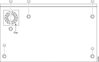
Step 4 Place the gateway right-side up on a flat, smooth, secure surface.
 |
Caution Do not place anything on top of the gateway that weighs more than 10 pounds (4.5 kg). Excessive weight on top could damage the chassis. |
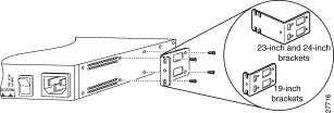
This section describes the procedures for rack-mounting the chassis. The chassis comes with brackets for use with a 19-inch rack or, if specified in your order, optional larger brackets for use with a 23- or 24-inch rack. The brackets are shown below.
 |
Warning To prevent bodily injury when mounting or servicing this unit in a rack, you must take special precautions to ensure that the system remains stable. The following guidelines are provided to ensure your safety: |
 |
Note There are two bracket sizes. You will need this information later to assist you with the mounting process. |

To install the chassis in a rack, attach the brackets in one of the following ways:
 |
Note Use the Cisco-supplied screws for this installation. |
 |
Note If you are installing a Cisco VG200 in a 19-inch rack with a 17.5-inch opening, orient the rack-mount brackets so that, when installed, they do not increase the width of the chassis. If you are installing a Cisco VG200 in a 19-inch EIA-standard rack with a 17.75-inch opening or a 23- or 24-inch rack, orient the rack-mount brackets so that, when installed, they increase the width of the chassis. |
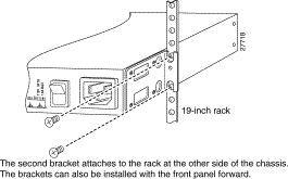
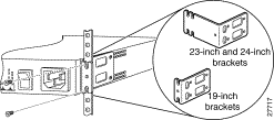
The following illustrations show how to connect the bracket to one side of the chassis. The second bracket connects to the opposite side of the chassis.
 |
Caution Use only screws provided with your Cisco VG200 to mount each brackets to the chassis. |
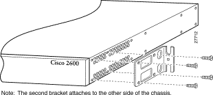
 |
Note When installed in a 19-inch rack with a 17.75-inch opening, the Cisco VG200 will protrude beyond the front of the rack. |
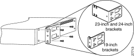

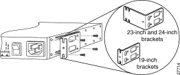
After the brackets are secured to the chassis, you can rack-mount it. Using screws that you provide, attach the chassis to the rack.
 |
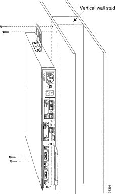
Note Use 19-inch brackets to wall-mount the chassis. The small brackets provide the most stable installation for the chassis. |
Perform the following steps to wall-mount the chassis:

Step 2 Attach the chassis assembly to the wall as shown in Figure 3-11, using screws and anchors that you provide. We recommend the following:
This section explains how to use the Ethernet ports to connect the Cisco VG200 to the LAN.
For information about cable pinouts, refer to the publication Cisco Modular Access Router Cabling Specifications, available on the Documentation CD-ROM that came with your gateway, and on Cisco Connection Online (CCO).
 |
Warning The ports labeled Ethernet, 10BaseT, Serial, Console, and AUX contain safety extra-low voltage (SELV) circuits. PRI circuits are treated like telephone-network voltage (TNV) circuits. Avoid connecting the SELV circuit to the TNV circuits. |
 |
Warning Do not work on the system, or connect or disconnect cables during periods of lightning activity. |
To connect your gateway to a network, connect the Ethernet 10BaseT port to an Ethernet hub, as shown in Figure 3-13. Or, connect the Ethernet 10BaseT port directly to a switch such as a Cisco Catalyst 3900.
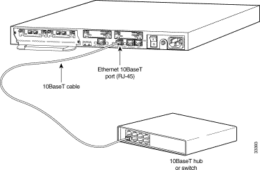
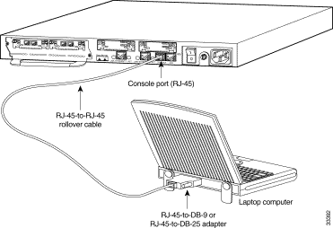
Your Cisco VG200 includes asynchronous serial console and auxiliary ports. These ports provide administrative access to your gateway either locally (with a console terminal) or remotely (with a modem).
Use a rollover cable to connect to the asynchronous serial console and auxiliary ports. You can identify a rollover cable by comparing the two modular ends of the cable. Hold the cables side by side, with the tab at the back. The wire connected to the pin on the outside of the left plug should be the same color as the wire connected to the pin on the outside of the right plug. (See Figure 3-14.) If your cable came from Cisco Systems, pin 1 will be white on one connector, and pin 8 will be white on the other connector (a rollover cable reverses pins 1 and 8, 2 and 7, 3 and 6, and 4 and 5).
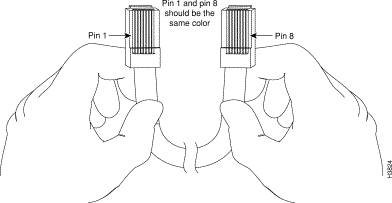
Perform the following steps to connect a terminal (an ASCII terminal or a PC running terminal emulation software) to the console port on the Cisco VG200:
Step 2 Configure your terminal or PC terminal emulation software for the following settings:
| Setting | Value |
Baud | 9600 |
Data bits | 8 |
Parity | No |
Stop bits | 2 |
For information on console port pinouts, refer to the online publication Cisco Modular Access Router Cabling Specifications on the Documentation CD-ROM that accompanied your gateway package, and on CCO.
Perform the following steps to connect a modem to the auxiliary port on the Cisco VG200:
 |
Warning This equipment is intended to be grounded. Ensure that the host is connected to earth ground during normal use. |
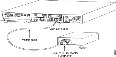
For information on console port pinouts, refer to the online publication Cisco Modular Access Router Cabling Specifications on the Documentation CD-ROM that accompanied your gateway package, and on CCO.
After you have installed the Cisco VG200, connect the power cable to the rear panel of the gateway and the power source, and then power on the unit. (If the gateway does not power on, proceed to Appendix A "Troubleshooting the Gateway.")
Refer to the publication Software Configuration Guide for the Cisco VG200, included in your package, for software configuration information.
![]()
![]()
![]()
![]()
![]()
![]()
![]()
![]()
Posted: Mon Jun 12 12:56:22 PDT 2000
Copyright 1989 - 2000©Cisco Systems Inc.