cc/td/doc/product/voice/ata/ataadmn
hometocprevnextglossaryfeedbacksearchhelp
PDF

Table Of Contents

Cisco Analog Telephone Adaptor Overview

H.323 Overview

H.323 Terminals

H.323 Gateways

H.323 Gatekeepers

H.323 MCUs

H.323 Proxy Server

Hardware Overview

Software Features

Voice Codecs Supported

Additional Supported Signaling Protocols

Other Supported Protocols

Cisco ATA H.323 Services

Fax Services

Supplementary Services

Installation and Configuration Overview

Cisco Analog Telephone Adaptor Overview


This section describes the hardware and software features of the Cisco Analog Telephone Adaptor (Cisco ATA) and includes a brief overview of the H.323 protocol.

The Cisco ATA analog telephone adaptors are handset-to-Ethernet adaptors that allow regular analog telephones to operate on IP-based telephony networks. Cisco ATAs support two voice ports, each with an independent telephone number. The Cisco ATA 188 also has an RJ-45 10/100BASE-T data port.

This section covers the following topics:

H.323 Overview

Hardware Overview

Software Features

Installation and Configuration Overview

Figure 1-1 Cisco ATA Analog Telephone Adaptor

The Cisco ATA, which operates with Cisco voice-packet gateways, makes use of broadband pipes that are deployed through a digital subscriber line (DSL), fixed wireless-cable modem, and other Ethernet connections.


Note The term Cisco ATA refers to both the Cisco ATA 186 and the Cisco ATA 188, unless otherwise stated.


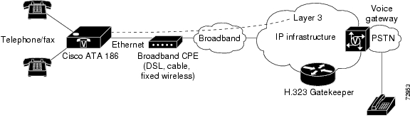
Figure 1-2 Cisco ATA 186 as Endpoint in an H.323 Network

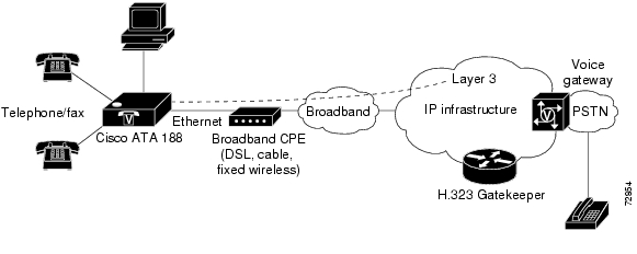
Figure 1-3 Cisco ATA 188 as Endpoint in an H.323 Network

H.323 Overview

H.323 is the International Telecommunication Union (ITU) standard for transmitting voice, video, and data across an IP network. Like other VoIP protocols, the H.323 standard is designed to address the functions of signaling and session management from within a packet telephony network. Signaling allows call information to be carried across network boundaries. Session management provides the ability to control the attributes of an end-to-end call. The H.323 standard includes support for call signaling and control, multimedia transport and control, and bandwidth control for both point-to-point and point-to-multipoint conferences.

The H.323 standard includes the following protocols:

Call signaling using the H.225 protocol

Media control using the H.245 protocol

G.711, G.722, G.723, G.728, and G.729 audio codecs

H.261 and H.263 video codecs

Data sharing using the T.120 protocol

Real-time transport protocol (RTP) and RTP Control Protocol (RTCP) for media transport

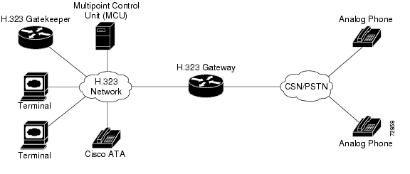
Components that the H.323 standard employs include a system of interconnected voice terminals, gateways, gatekeepers, multipoint control units (MCUs), and proxy servers. Voice terminals provide point-to-point and point-to-multipoint conference capability for audio, video, and data. Voice gateways interconnect the packetized IP network to the PSTN or ISDN network. Gatekeepers provide admission control and address translation services for H.323 voice terminals and gateways. MCUs enable two or more gateways to engage in point-to-point or point-to-multipoint audio or video conferences.

This section contains descriptions of the following H.323 components:

H.323 Terminals

H.323 Gateways

H.323 Gatekeepers

H.323 MCUs

H.323 Proxy Server

Figure 1-4 H.323 Architecture

H.323 Terminals

Voice terminals in an H.323 network must feature system control units, media transmission capabilities, audio codecs, and network interfaces suitable for transmitting and receiving packetized data.

H.323 Gateways

H.323 gateways feature a mixture of characteristics of both standard Switched Circuit Network (SCN) access points and H.323 access points. Gateways perform the translation of audio, video, and data transmission formats as well as interacting with communications systems and various protocols. A primary responsibility of an H.323 gateway is the call setup and teardown necessary to complete a call to and from a packetized IP network and a standard switched network.


Note Gateways are necessary in an H.323 system to connect calls over a packetized IP network to a switched circuit network such as the PSTN.


H.323 Gatekeepers

Gatekeepers are primarily responsible for pre-call and call-level control services for H.323 gateways. Gatekeepers are an optional component in an H.323 system. However, if present, gatekeepers must perform the following call setup and management services:

Address translation for IP addresses originating from H.323 aliases (for example, address_pool@cisco.com, for example) or E.164 addresses (for example, standard telephone numbers)

Admissions control for authorizing or rejecting access to H.323

Bandwidth control for gateway bandwidth requirements

Zone management for registered voice terminals, gateways and MCUs

When used in an H.323 system, gatekeepers can also (but are not required to) provide the following functionality:

Call control signaling using the gatekeeper Routed Call Signaling model

Call authorization to restrict access to certain voice terminals or gateways, or to restrict access based on time-of-day criteria

Bandwidth management for the H.323 system that will enable the gateway to restrict access when requested bandwidth is unavailable

Call management including maintaining a list of active calls to indicate available and unavailable voice terminals and gateways

H.323 MCUs

MCUs are endpoints in an H.323 network that support point-to-multipoint conferences and consist of a multipoint controller and at least one multipoint processor responsible for receiving voice, video, and data streams. These streams are distributed to access points participating in a point-to-multipoint conference.

H.323 Proxy Server

An H.323 proxy server is a proxy specifically designed for the H.323 protocol and examines packets between two communicating applications. Proxies can determine the destination of a call and perform call-connection steps, if necessary.

H.323 proxies perform the following key functions:

Allow voice terminals that do not support Resource Reservation Protocol (RSVP) to connect to the proxy through remote access or local area networks with relatively reliable quality of service (QoS). Pairs of proxies can then be employed to develop tunnels across the IP network.

Support routing of H.323 traffic that is separate from ordinary data traffic by using application-specific routing (ASR).

Enable H.323 to be deployed in networks that use private address space.

Ensure network security by configuring the proxy server to allow only H.323 traffic over the network.

Hardware Overview

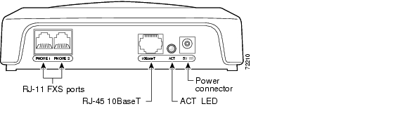
The Cisco ATA 186 and Cisco ATA 188 are compact, easy-to-install devices. Figure 1-5 shows the rear panel of the Cisco ATA 186. Figure 1-6 shows the rear panel of the Cisco ATA 188.

Figure 1-5 Cisco ATA 186—Rear View

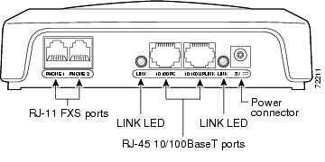
Figure 1-6 Cisco ATA 188—Rear View

The unit provides the following connectors and indicators:

5V power connector.

Two RJ-11 FXS (Foreign Exchange Station) ports—The Cisco ATA supports two independent RJ-11 telephone ports that can connect to any standard analog telephone device. Each port supports either voice calls or fax sessions, and both ports can be used simultaneously.


Note The Cisco ATA186-I1 and Cisco ATA188-I1 provide 600-ohm resistive impedance. The Cisco ATA 186-I2 and Cisco ATA188-I2 provide 270 ohm + 750 ohm // 150-nF complex impedance. The impedance option is requested when you place your order and should match your specific application. If you are not sure of the applicable configuration, check your country or regional telephone impedance requirements.


Ethernet ports

The Cisco ATA 186 has one RJ-45 10BASE-T uplink Ethernet port to connect the Cisco ATA 186 to a 10/100BASE-T hub or another Ethernet device.

The Cisco ATA 188 has two Ethernet ports: an RJ-45 10/100BASE-T uplink port to connect the Cisco ATA 188 to a 10/100BASE-T hub or another Ethernet device and an RJ-45 10/100BASE-T data port to connect an Ethernet-capable device, such as a computer, to the network.


Note The Cisco ATA 188 performs auto-negotiation for duplexity and speed and is capable of 10/100 Mbps, full-duplex operation. The Cisco ATA 186 is fixed at 10 Mbps, half-duplex operation.


The Cisco ATA 188 RJ-45 LED shows network link and activity. The LED blinks twice when the Cisco ATA is first powered on, then turns off if there is no link or activity. The LED blinks to show network activity and is solid when there is a link.

The Cisco ATA 186 RJ-45 LED is solid when the Cisco ATA is powered on and blinks to show network activity.

Function button—The function button is located on the top panel of the unit (see Figure 1-7).

Figure 1-7 Function Button

The function button lights when you pick up the handset of a telephone attached to the Cisco ATA. The button blinks quickly when the Cisco ATA is upgrading its configuration.


Note If the function button blinks slowly, the Cisco ATA cannot find the DHCP server. Check your Ethernet connections and make sure the DHCP server is available.


Pressing the function button allows you to access to the voice configuration menu. For additional information about the voice configuration menu, see the "Voice Configuration Menu" section on page 3-20.


Caution Never press the function button during an upgrade process. Doing so may interfere with the process.

Software Features

The Cisco ATA supports the following protocols, services and methods:

Voice Codecs Supported

Additional Supported Signaling Protocols

Other Supported Protocols

Cisco ATA H.323 Services

Fax Services

Supplementary Services

Voice Codecs Supported

The Cisco ATA supports the following voice codecs (check your other network devices for the codecs they support):

G.711µ-law

G.711A-law

G.723.1

G.729

G.729A

G.729B

G.729AB

Additional Supported Signaling Protocols

In addition to H.323, the Cisco ATA supports the following signaling protocols:

Session Initiation Protocol (SIP)

Skinny Client Control Protocol (SCCP)

Media Gateway Control Protocol (MGCP)

If you wish to perform a cross-protocol upgrade from H.323 to another signaling image, see the "Upgrading the Signaling Image from a TFTP Server" section.

Other Supported Protocols

Other protocols that the Cisco ATA supports include the following:

802.1Q VLAN tagging

Cisco Discovery Protocol (CDP)

Domain Name System (DNS)

Dynamic Host Configuration Protocol (DHCP)

Internet Control Message Protocol (ICMP)

Internet Protocol (IP)

Real-Time Transport Protocol (RTP)

Transmission Control Protocol (TCP)

Trivial File Transfer Protocol (TFTP)

User Datagram Protocol (UDP)

Cisco ATA H.323 Services

For a list of required H.323 parameters as well as descriptions of all supported Cisco ATA H.323 services and cross references to the parameters for configuring these services, see Chapter 4, "Basic and Additional H.323 Services."

These services include the following features:

Supports direct IP dialing to and from a Cisco ATA without using an H.323 gatekeeper

Supports direct IP dialing in addition to proxy-routed calls to and from either phone

Uses the same configurable MediaPort to transmit and receive RTP audio

Uses UDP only for H.323 RAS message transmission

Uses a TCP connection for H.225/Q.931 signaling (such as call setup, call proceeding, alerting, and call connect)

IP address assignment—DHCP-provided or statically configured

Cisco ATA configuration by means of a TFTP server, web browser, or voice configuration menu.

VLAN configuration

Cisco Discovery Protocol (CDP)

Low-bit-rate codec selection

User authentication

Configurable tones (dial tone, busy tone, alert tone, reorder tone, call waiting tone)

Dial plans

User-configurable, call-waiting, permanent default setting

Silence suppression and comfort noise generation for G.711, G.723.1 (G.723.1 Annex A), and G.,729 (G.729 Annex B)

Caller ID format

Ring cadence format

Hook-flash detection timing configuration

Type of Service (ToS) configuration for audio and signaling ethernet packets

Hotline and warmline support (private line automatic ringdown)

Debugging and diagnostic tools

Fax Services

The Cisco ATA supports two modes of fax services, in which fax signals are transmitted using the G.711 codec:

Fax pass-through mode—Receiver-side Called Station Identification (CED) tone detection with automatic G.711A-law or G.711µ-law switching.

Fax mode—The Cisco ATA is configured as a G.711-only device.

How you set Cisco ATA fax parameters depends on what network gateways are being used. You may need to modify the default fax parameter values (see Chapter 7, "Configuring and Debugging Fax Services").


Note Success of fax transmission depends on network conditions and fax modem response to these conditions. The network must have reasonably low network jitter, network delay, and packet loss rate.


Supplementary Services

H.323 supplementary services are services that you can use to enhance your telephone service. For information on how to enable and subscribe to these services, see the "CallFeatures" section on page 5-27 and the "PaidFeatures" section on page 5-28.

For information on how to use these services, see "Using H.323 Supplementary Services."

The following list contains the H.323 supplementary services that the Cisco ATA supports:

Caller ID

Calling line ID presentation/rejection (CLIP/CLIR)

Call waiting

Call waiting Caller ID

Three-way calling

Installation and Configuration Overview

Table 1-1 provides the basic steps required to install and configure the Cisco ATA to make it operational.

Table 1-1 Overview of the Steps Required to Install and Configure the Cisco ATA and Make it Operational 

Action
Reference

1. Plan the network and Cisco ATA configuration.


2. Install the Ethernet connection.


3. Install and configure the other network devices.


4. Install the Cisco ATA but do not power up the Cisco ATA yet.

What the Cisco ATA Package Includes

5. Download the desired Cisco ATA release software zip file from the Cisco web site, then configure the Cisco ATA.

Chapter 3, "Configuring the Cisco ATA for H.323"

6. Power up the Cisco ATA.


7. Periodically, you can upgrade the Cisco ATA to a new signaling image by using the TFTP server-upgrade method or the manual-upgrade method.

"Upgrading the Cisco ATA Signaling Image"


hometocprevnextglossaryfeedbacksearchhelp

Posted: Fri Apr 2 13:03:09 PST 2004
All contents are Copyright © 1992--2004 Cisco Systems, Inc. All rights reserved.
Important Notices and Privacy Statement.