|
|

This chapter presents call processing examples that illustrate the interaction of inpulse and outpulse rules, answer supervision templates, and host commands/reports for a variety of applications. Each example begins with a brief explanation of the scenario, followed by a graphic representation of the call flow. These diagrams provide information on system processing and information flow between the system and host, and the system and connected equipment. Direction of information flow is indicated by an arrow under the message data. In situations involving supervision signaling over both incoming and outgoing ports, the diagrams indicate which piece of connected equipment is generating/receiving the signals by specifying incoming or outgoing in the connected equipment column.
 |
Note All of the following examples are constructed for the VCO/4K Standard Programming Mode. For more information about the VCO/4K Extended Programming Mode, refer to the Cisco VCO/4K Extended Programming Reference. |
The resources used in these examples are summarized in Table 6-1.
| Port Type | Port Address | Resource Group | Class of Service (COS) | Default Inpulse Rule | Connected Equipment | |
|---|---|---|---|---|---|---|
| Individual or Card Range | Number | Rehunt? | ||||
ICC T1 I/O | $00 12 to $00 2A | 11 | — | T | 1 | Central Office |
ICC T1 I/O | $00 34 to $00 4B | 3 | No | O | — | Central Office |
ICC T1 I/O | $00 42 to $00 5A | 2 | Yes | O | — | Central Office |
ICC T1 I/O | $00 8F | 1 | Yes | — | — | — |
SPC CPA | $00 C5 | 8 | Yes | — | — | — |
Virtual | $80 01 | $FE | — | — | — | — |
Additional system configuration information, including inpulse rules, outpulse rules, and answer supervision templates used in each scenario, accompanies the text explanation.
 |
Note These examples assume the Enable Digit Field Reporting feature flag is set to Y. This setting causes the digit field number to appear in the Optional Field Designator (byte offset 12) in all MF Digit ($D0) and DTMF Digit ($D1) reports. |
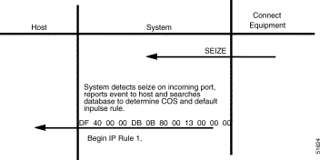
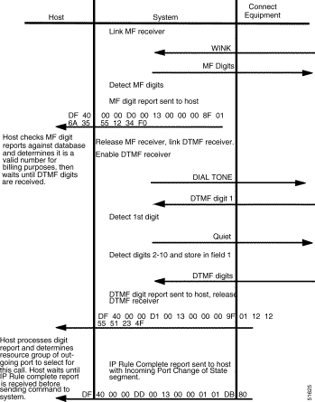
The example in this section illustrates a simple supervision signaling and digit collection scenario after an incoming seize on the trunk circuit at port address $00 13. This example involves both an MF collection (signaling information between COs, such as ANI) and DTMF collection (destination digits). A wink signal when the MF receiver is enabled alerts the near-end CO to send the MF digits. The system generates a dial tone after the DTMF receiver is enabled, prompting the calling party to dial the destination digits.
At the end of this example, the incoming call remains in setup state awaiting further host action. The default inpulse rule, rule #1, tokens and parameter values are as follows:
The processing flow for this example is illustrated in Figure 6-1 and Figure 6-2.
This section includes three variations of supervision timing: supervision error, call failure, and grace timing. The outpulse rules used in each scenario contain TIME SUP [xx] tokens which start supervision timers at the beginning of template processing.
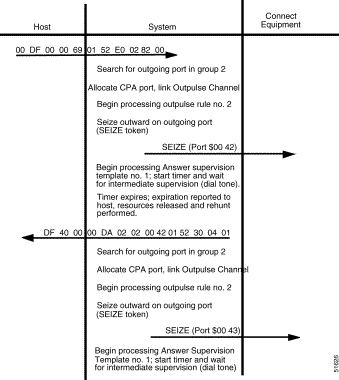
The example in this section illustrates supervision error timing during intermediate supervision. Assume the system has processed an incoming seizure at port address $00 12 and performed a DTMF digit collection. Based on an Outgoing Port Control ($69) host command, the system hunts an outgoing port ($00 42) from Resource Group 2.
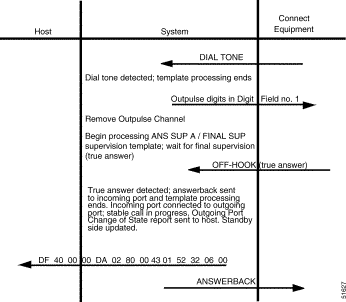
The expected supervision event for intermediate supervision is dial tone. (See answer supervision template #1 in Table 6-2.) The system waits 5 seconds to detect a dial tone before a timer expires. The expiration of the timer indicates a supervision error and causes a rehunt for another outgoing trunk. When the system successfully rehunts another outgoing port ($00 43) and detects a dial tone, the system outpulses the DTMF digits stored in Digit Field #1. Because no FINAL SUP token was specified in the rule and answerback was not generated during intermediate supervision processing, the system automatically processes an ANS SUP A / FINAL SUP template after rule processing completes.The command specifies to use outpulse rule #1, described as follows:
| Template Field | Condition Token |
|---|---|
Dial Tone | OK |
Ringback | — |
Busy | FAIL |
Reorder | FAIL |
SIT Tones | FAIL |
Ring Cess. | — |
Voice Det. | — |
Voice Cess. | — |
Wink | ERROR |
Answer | ERROR |
Time | ERROR |
Hookflash | — |
Pager Queue | — |
The processing flow for this example is illustrated in Figure 6-3 and Figure 6-4.
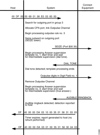
The example in this section presents a situation when a timer expiration indicates a call failure. Assume the system has processed an incoming seizure at port address $00 12 and performed a DTMF digit collection. Based on an Outgoing Port Control ($69) host command, the system hunts an outgoing port ($00 35) from Resource Group 3.
The system seizes out on the outgoing port and waits for dial tone (answer supervision template #1). When the system detects dial tone, it outpulses the DTMF digits stored in Digit Field #1. Outpulse rule processing ends and final supervision processing begins. A 24-second timer runs while the system waits to detect true answer (answer supervision template #3—seeTable 6-3). The system detects audible ringback and reports it to the host. If the call is not answered after 4 or 5 rings (depending at what point in the ringback cycle the timer began), the timer expires and the call fails.
The command uses outpulse rule #2, described as follows:
| Template Field | Condition Token |
|---|---|
Dial Tone | — |
Ringback | REP |
Busy | FAIL |
Reorder | ERROR |
SIT Tones | FAIL |
Ring Cess. | — |
Voice Det. | — |
Voice Cess. | — |
Wink | — |
Answer | ANSREP |
Time | FAIL |
Hookflash | — |
Pager Queue | — |
The processing flow for this example is illustrated in Figure 6-5.
The example in this section illustrates the use of grace timing. Grace timers provide time for a supervision event to occur when the timer expires; the system assumes the event occurred (even if no event was detected) and acts accordingly.
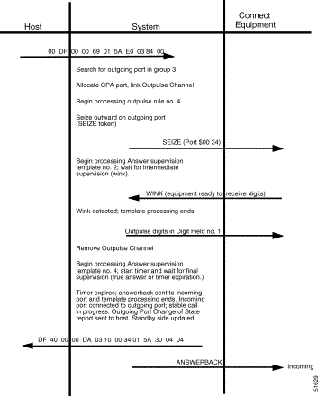
For this scenario, assume the system has processed an incoming seizure at port address $00 12 and performed a DTMF digit collection. Based on an Outgoing Port Control ($69) host command, the system hunts an outgoing port ($00 34) from Resource Group 3.
The system seizes out on the outgoing port and waits for a wink signal (answer supervision template #3—see Table 6-3). When the system detects the wink (indicating that the far-end equipment is ready to receive digits), it outpulses the DTMF digits stored in Digit Field #1. Outpulse rule processing ends and final supervision processing begins. An 18-second timer runs while the system waits to detect true answer (answer supervision template #4—see Table 6-4). If either true answer is detected or the grace timer expires, the system considers the port answered and assumes the incoming and outgoing ports are involved in a stable call (regardless of the on-hook/off-hook status of the ports). The detection of either supervision event generates answerback over the incoming port.
The command specifies to use outpulse rule #3, described below:
| Template Field | Condition Token |
|---|---|
Dial Tone | — |
Ringback | — |
Busy | FAIL |
Reorder | ERROR |
SIT Tones | FAIL |
Ring Cess. | — |
Voice Det. | — |
Voice Cess. | — |
Wink | ERROR |
Answer | ANSREP |
Time | ANSREP |
Hookflash | — |
Pager Queue | — |
The processing flow for this example is illustrated in Figure 6-6.
The example in this section uses answer supervision template #2 (see Table 6-5) to demonstrate the system's handling of an error condition on an outgoing port.
| Template Field | Condition Token |
|---|---|
Dial Tone | — |
Ringback | ERROR |
Busy | FAIL |
Reorder | ERROR |
SIT Tones | FAIL |
Ring Cess. | — |
Voice Det. | — |
Voice Cess. | — |
Wink | OKREP |
Answer | ERROR |
Time | — |
Hookflash | — |
Pager Queue | — |
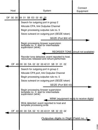
The system responds to the detection of reorder and SIT tones without host intervention. For this scenario, assume the system has processed an incoming seize at port address $00 12 and performed a DTMF digit collection. Based on an Outgoing Port Control ($69) host command, the system hunts an outgoing port ($00 42) from resource group 2.
The system seizes out on the outgoing port to a CO and waits for a wink signal. However, the selected trunk circuit between this CO and the far end CO is disabled and is not available for outgoing calls. The connected CO sends reorder tone to the system to alert the system of the error condition. When the system detects reorder tone, it generates a report to the host indicating the circuit's condition and performs a rehunt.
The system rehunts from resource group 2 and attempts to complete the call on the port at $00 43. outpulse rule and template processing begins again. When the system successfully detects a wink over the new circuit, it outpulses the digits in Digit Field #2. The command specifies outpulse rule #4, described below:
The processing flow for this example is illustrated in Figure 6-7.
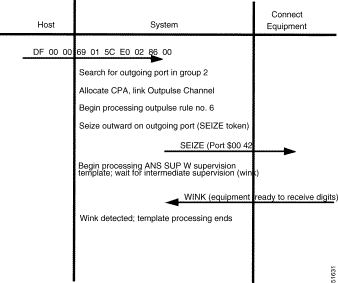
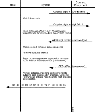
The example in this section illustrates the use of multiple intermediate supervision events during call processing. In this example, the system is being used to route calls to various Inter-Exchange Carriers. The system passes both calling party identification and destination numbers in MF form. The calling parties identification number is stored in the ANI field. The destination (called party) digits reside in Digit Field #2. Assume this information was obtained from an incoming port at $00 12. Based on an Outgoing Port Control ($69) host command, the system hunts an outgoing port ($00 42) from resource group 2.
The system seizes out on the outgoing port and waits for a wink signal using the preconfigured ANS SUP W template. When the system detects a wink, it outpulses the MF digits in ANI Digit Field (calling party ID). The system pauses for 0.5 seconds and then outpulses the destination digits in Digit Field #2. The system waits for another wink from the connected equipment (acknowledging the receipt of both sets of digits). Once the wink acknowledgment is received, outpulse rules processing ends and the system waits for answer supervision from the far end. The template allows for an early indication of busy conditions or network problems (SITs) before the call continues. The command specifies to use outpulse rule #6, described as follows:
| Template Field | Condition Token |
|---|---|
Dial Tone | — |
Ringback | — |
Busy | FAIL |
Reorder | ERROR |
SIT Tones | FAIL |
Ring Cess. | — |
Voice Det. | — |
Voice Cess. | — |
Wink | — |
Answer | ANS REP |
Time | — |
Hookflash | — |
Pager Queue | — |
The processing flow for this example is illustrated in Figure 6-8 and Figure 6-9.
![]()
![]()
![]()
![]()
![]()
![]()
![]()
![]()
Posted: Sat Sep 28 14:43:04 PDT 2002
All contents are Copyright © 1992--2002 Cisco Systems, Inc. All rights reserved.
Important Notices and Privacy Statement.