|
|

Table Of Contents
SS7 Signal Units
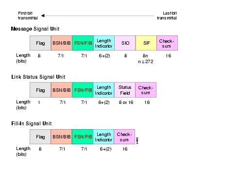
Signaling information is passed over the signaling links in messages, which are called signal units. Signal units are continuously transmitted in both directions on any link that is in service. (See Figure 4-1.) SS7 uses three different types of signal units:
•
Message Signal Units (MSUs)
•
•
A signaling point sends FISUs over the link when it does not have any MSUs or LSSUs to transmit.
Signal Unit Structure
All types of signal units (MSU, LSSU, FISU) have a set of common fields which are used by MTP Level 2. Field types include the following:
•
0111 1110).
Note
•
•
•
Figure 4-1 SS7 Signal Unit Types
Signal Unit Flow Control
The BSN/BIB and FSN/FIB fields in a signal unit (SU) confirm receipt of SUs and ensure that they are received in the order in which they were transmitted. These fields also provide flow control.
MSUs and LSSUs are assigned a sequence number when transmitted. That sequence number is placed in the FSN field of the outgoing signal unit, which is stored by the transmitting signaling point until it is acknowledged by the receiving signaling point. Signaling points acknowledge receipt of SUs by putting the sequence number of the last correctly received (and in sequence) SU in the backward sequence number (BSN) of every SU they transmit.
SU Error Detection
The check bit field and the sequence number of the signal unit are used to detect errors. Seven-bit sequence numbering is used. The forward sequence number (FSN) is incremented by one after every transmission. The backward sequence number (BSN) is used to acknowledge received signal units.
The transmitting signal point keeps all transmitted signal units in a buffer until acknowledged. Once the BSN is received, all acknowledged signal units are dropped from the buffer. Unacknowledged signal units stay in the buffer until a timer expires, causing a link failure indication to be sent to Level 3. The link is then tested and aligned.
Types of Signal Units
Message Signal Units
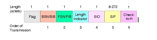
MSUs are the workhorses of the SS7 network. All signaling associated with call setup and teardown, database query and response, and SS7 management requires the use of MSUs. (See Figure 4-2.)
MSUs provide MTP protocol fields, service indicator octet (SIO) and service information field (SIF). The SIO identifies the type of protocol (ISUP, TCAP) and standard (ITU-TS, ANSI). The SIF transfers control information and routing label.
Figure 4-2 MSU Format
SIO Structure
The functionality of the MSU lies in the contents of the service indicator octet (SIO) and the service information fields (SIF). The SIO is an 8-bit field that contains three types of information:
•
•
•
Table 4-1 SIO Service Indicator Bits
0
Signaling Network Management
1
Signaling Network Testing and Maintenance
2
Signaling Connection Control Part (SCCP)
3
ISDN User Part (ISUP)
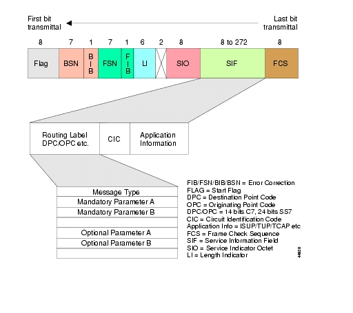
SIF Structure
The service information field (SIF) provides the first piece of information necessary for routing and decoding the message. The SIF transfers control information and the routing label used by Level 3.
The routing label consists of the destination point code (DPC), originating point code (OPC) and signaling link selection (SLS) fields.
Note
The SIF can contain up to 272 octets and is used by network management, ISUP, TCAP and MAP. (See Figure 4-3.)
Figure 4-3 MSU SIF Structure
Link Status Signal Unit
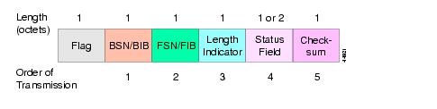
LSSUs communicate information about the signaling link between the nodes on either end of the link. This information is contained in the status field of the signal unit. (See Figure 4-4.) They signal the initiation of link alignment, quality of received traffic, and status of processors at either end of the link.
LSSUs do not require any addressing information because they are only sent between signaling points.
Figure 4-4 LSSU Format
Fill-in Signal Unit
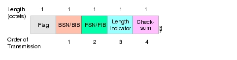
FISUs do not carry any information; they simply occupy the link when there are no LSSUs or MSUs. FISUs support the monitoring of link traffic because they undergo error checking. They can also be used to acknowledge the receipt of messages using backward sequence number (BSN) and backward indicator bit (BIB). (See Figure 4-5.)
Figure 4-5 FISU Format
Link Alignment
When all signal units are received in sequence without ones-density violations and with the proper number of octets, the link is considered to be in alignment. The link is considered in error if the signal unit is not in 8-bit multiples or if the SIF exceeds the maximum 272-octet capacity.
The system uses a counter called the Signal Unit Error Rate Monitor (SUERM). Each link keeps its own unique counter. When more than 64 errors occur, the link is taken out of service, tested, and realigned by Level 3.
Review: Signal Units
1.
2.
3.
4.
5.
6.
7.
8.
9.
10.
11.
12.
![]()
![]()
![]()
![]()
![]()
![]()
![]()
![]()
Posted: Wed Jun 9 14:25:17 PDT 2004
All contents are Copyright © 1992--2004 Cisco Systems, Inc. All rights reserved.
Important Notices and Privacy Statement.