|
|

This chapter provides examples of R2 signaling performed with the following call control elements:
Two examples discuss R2 digit collections on incoming trunks (calls coming into the VCO/4K); a third example describes R2 digit outpulsing on outgoing trunks (calls originating at the VCO/4K). Each example begins with a brief explanation of the scenario, followed by a graphic representation of the call flow. These diagrams illustrate system processing and information flow between the VCO/4K and host, and between the VCO/4K and connected equipment (network registers). Direction of the information flow is indicated by arrows under the message data.
Example #1 illustrates a simple R2 digit collection scenario after an incoming seize on the system E1 circuit at port address $00 41. A New Zealand specific inpulse rule is executed to perform R2 digit collection on this circuit. The rule generates a wink signal when an MFCR2 transceiver is enabled to alert the network register to send the R2 signals.
The inpulse rule performs the following general tasks:
At the end of this example, the system establishes speech conditions with the connected equipment (network register) and generates an Inpulse Rule Complete ($DD) report to the host. The processing flow for this example is shown in Figure 4-1 to Figure 4-3. In this example, the New Zealand specific inpulse rule for the incoming circuit has been defined as inpulse rule #1 (shown below).
Inpulse Rule #1
For information on inpulse rule tokens, refer to the Cisco VCO/4K System Administrator's Guide.
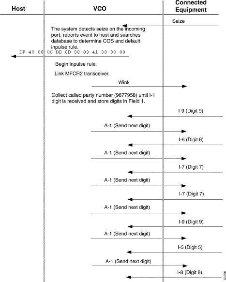
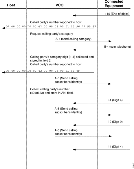
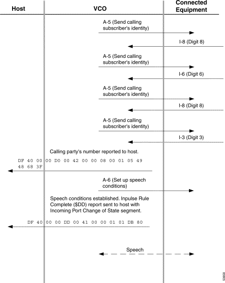
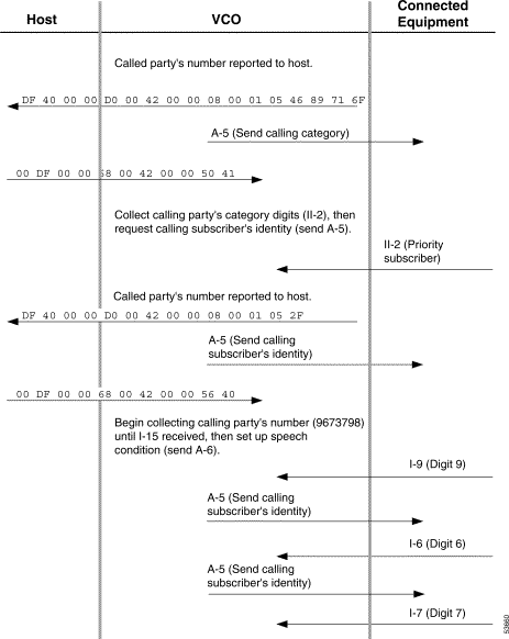
Example #2 also illustrates a simple R2 digit collection scenario on an incoming E1 circuit (port address $00 42). However, all R2 digit collections in this scenario are initiated by host command; no inpulse rule processing is used. Three MF Collection Control ($68) commands perform the following actions:
Each digit collection is reported to the host via an MF Digit ($D0) report.
At the end of this example, the system establishes speech conditions with the connected equipment (network register). The processing flow for this example is shown in Figure 4-4 to Figure 4-6.
Refer to the Cisco VCO/4K Standard Programming Reference or the Cisco VCO/4K Extended Programming Reference for complete descriptions of the $68 command and $D0 report.
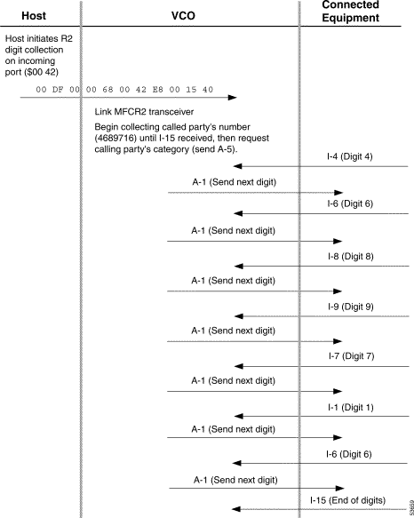

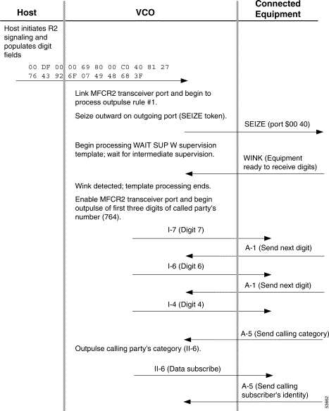
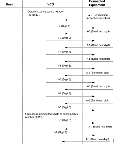
Example #3 describes R2 digit outpulsing on an E1 circuit at port address $00 40. This scenario involves both host command and outpulse rule processing. The host initiates the outpulsing using an Outgoing Port Control ($69) command that populates the digit fields and specifies the outpulse rule to execute (refer to the Cisco VCO/4K Standard Programming Reference or the Cisco VCO/4K Extended Programming Reference for a command description).
The outpulse rule performs the following actions:
This rule is shown below.
Outpulse Rule #1
At the end of this example, the system establishes speech conditions with the connected equipment (network register) and generates an Outgoing Port Change of State ($DA) report to the host. The processing flow for this example is shown in Figure 4-8.
Refer to the Cisco VCO/4K System Administrator's Guide for more information on MFCR2, OP ANUM, OP FIELD [xx], and OP CAT [xx] outpulse rule tokens.

![]()
![]()
![]()
![]()
![]()
![]()
![]()
![]()
Posted: Tue Oct 15 16:20:18 PDT 2002
All contents are Copyright © 1992--2002 Cisco Systems, Inc. All rights reserved.
Important Notices and Privacy Statement.