|
|

This chapter describes the procedures for installing and connecting a VCO/4K system. Before installation, read the Cisco VCO/4K Hardware Planning Guide, along with the Cisco VCO/4K Site Preparation Guide.
Use the checklist in the Cisco VCO/4K Site Preparation Guide to verify that the site is prepared according to the guidelines.
It is easier to install the system as it is unpacked. Therefore, move the crated system to the installation location before you begin.
Observe the following safety precautions:
 |
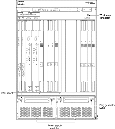
Note To decrease the weight and make the system easier to handle, you can remove the power supply modules from the front of the VCO/4K (see Figure 1-1 and the Open Me First documentation packed with the system). This is also explained in the following procedures. |
The VCO/4K system is shipped as a complete unit. All the system components, including circuit cards, power subsystems, and storage subsystems, are mounted in the system. Cisco Systems loads the generic software on the system hard disk(s) and provides generic software copies on 3.5-inch floppy disks.
Peripheral equipment (master consoles, printers, modems) and interconnecting cables ordered through Cisco Systems are identified on the shipping and packing lists and shipped in OEM or separate containers.
Inspect all cartons at the time of delivery for signs of damage during transit. Notify the carrier and your insurance company if there is any shipping damage.
Refer to the Open Me First instructions that come with the system for complete instructions on inspecting the container and unpacking the system.
After unpacking the system, inspect all cables and cards. Look for signs of misalignment or abrasion that might have occurred during shipping, or when the system was removed from the shipping container. If the inspection reveals any signs of shipping damage, contact your shipper.
You can install the VCO/4K system in a cabinet or rack, or on a table or the floor. The following sections contain checklists for installing the system in both configurations.
If you are installing the system in a cabinet or rack, set up the cabinet or rack and ensure that it is level and secured to the wall or floor before positioning the VCO/4K.
Secure the mounting shelf to the cabinet or rack and secure the mounting brace to the VCO/4K before lifting and placing it in the cabinet or rack.
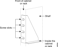
When installed in a cabinet or rack, the VCO/4K sits on the mounting shelf (included with the VCO/4K shipment). Secure the shelf to the cabinet or rack by tightening the screws through the screw slots into the cabinet.
Figure 1-2 shows the position of the mounting shelf on the cabinet or rack, and the screw slots.
Before installing the VCO/4K in the cabinet or rack, secure the brace at the preferred setback option.
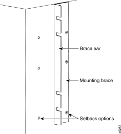
Figure 1-3 shows a mounting brace attached to a VCO/4K. The brace's ears are attached to the front of the cabinet or rack.
Note the setback options that are used for mounting in Figure 1-3. If the mounting brace is attached to the first option, the front of the VCO/4K is flush with the front of the cabinet or rack. If the brace is attached to the second setback option, the VCO/4K protrudes from the front of the cabinet or rack.
To make lifting the VCO/4K easier, you can remove the power supply modules with the following steps:
a. Unlock the door (if necessary).
b. Lift up on the two latch handles at the top.
c. Lift the door up and out.
Step 2 Remove the two mounting screws on each power supply module with a -Phillips-head screwdriver.
Step 3 Pull the two power supply modules out to disconnect them from the power backplane.
After securing the mounting brace and shelf on the cabinet or rack, install the VCO/4K with the following steps:
 |
Caution Use a minimum of two people to lift the system. |
Step 2 Secure the system to the cabinet or rack by tightening the screws in the screw slots (see Figure 1-2).
 |
Note Ensure that the VCO/4K is resting securely on the mounting shelf before you tighten the screws. |
Step 3 Verify that the fuses are correct before installing the power supply modules.
Each power supply module has one 25-amp fuse, either AC or DC power, and for either 120V at 50 Hz or 60 Hz, or 240V at 50 Hz or 60 Hz. The fuse is in the back of the power supply module.
Step 4 Connect the power supply modules before continuing.
a. Push the power supply modules in until they connect with the power backplane and are flush with the VCO/4K cabinet.
b. Secure the four mounting screws to the power supply modules with a Phillips-head screwdriver. Ensure that the black metal tabs are also secured.
Use the following checklist to ensure that each step is completed:
1. ___ Set up or prepare the rack for the system.
2. ___ Install the mounting shelf (included in the optional carton) in the rack.
3. ___ Install the mounting brace (included in the optional carton) on the VCO/4K.
4. ___ Remove the VCO/4K power supply modules from the bottom of the enclosure.
5. ___ Position the VCO/4K in the cabinet or rack.
6. ___ Bolt the VCO/4K to cabinet or rack.
If you are installing the system on the floor or a table, ensure that the system is level. Refer to the Cisco VCO/4K Site Preparation Guide for information on selecting and preparing an independent location for the VCO/4K.
A separate package contains rubber feet for installing the system on the floor or a table.
Installing the rubber feet on the system requires two people. Use the following steps:
Step 2 The second person screws the rubber feet to the bottom corners of the raised side.
Step 3 After the installer moves out from under the system, lower the enclosure.
Step 4 Repeat Step 1 and Step 2 for the other side.
Step 5 Verify that the fuses are correct before installing the power supply modules.
Step 6 Connect the power supply modules before continuing.
a. Push the power supply modules in until they connect with the power backplane and are flush with the VCO/4K cabinet.
b. Secure the four mounting screws to the power supply modules with a Phillips-head screwdriver. Ensure that the black metal tabs are also secured.
Use the following checklist to ensure that each step is completed:
1. ___ Ensure the installation location is level.
2. ___ Remove the VCO/4K power supply modules from the bottom of the enclosure.
3. ___ Install the rubber feet on the bottom of the VCO/4K.
4. ___ Position the VCO/4K.
 |
Caution A licensed electrician must connect the feeds to the power entry module on the VCO/4K system according to the chart on the inside of the power protection cover. |
The VCO/4K power subsystem receives electrical power from one three-conductor cable for single-line feed AC operation, two two-conductor cables for dual-line feed DC operation, or one one-conductor cable for single-line feed DC operation, all rated for 600 volts. Use a dedicated feed(s) [i.e., dedicated branch circuit(s)] and sufficiently sized conductors to route the power from a nearby power panel. Terminate the feed as a drop cable or in an appropriate outlet receptacle.
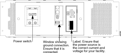
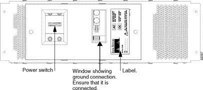
The power supply modules are identical; however, if a ring generator is present, it is installed in the left module. The type of input power (AC or DC) required by the VCO/4K is noted on the front of each power supply module. A label at the rear of your power entry module (PEM) will either specify your system's input power type (see Figure 1-4) or list both possibilities (see Figure 1-5). Always verify by looking at the front of each power supply module. Power travels from the power entry module to the power backplane, then to the power supply module which feeds the VCO/4K chassis.
 |
Caution Before connecting power to the VCO/4K, turn off the power switch on the power entry module (see Figure 1-4). |
See Table 1-1 for AC and DC wiring connections.
Place a voltmeter on the power feed(s) to ensure that the voltage is within the power ratings range (see Figure 1-4, Figure 1-5, and Table 1-2).
| Source | Range | Current | Frequency |
|---|---|---|---|
-48 VDC (per feed) | -40 to -60 VDC | 20 amps | DC |
120 VAC, single phase | 100 to 120 VAC | 10 amps | 50/60 Hz |
240 VAC, single phase | 208 to 240 VAC | 5 amps | 50/60 Hz |
 |
Warning Before you connect the power cable, ensure that the cable is not plugged in to the source. |
The following tools are required to connect the power cable to the power entry module (PEM):
Use the following steps to connect the power cable.
 |
Warning Do not open the power entry module (PEM) or you will void your Cisco Systems warranty. |
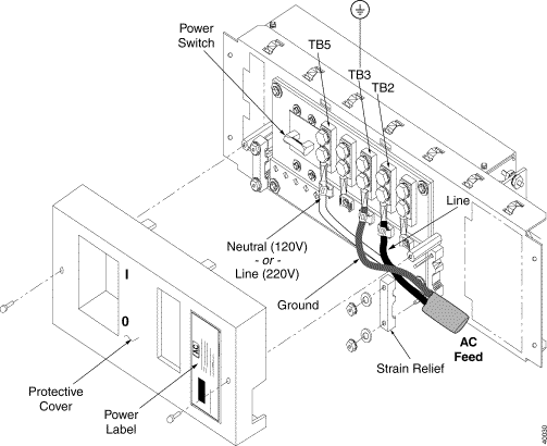
Step 2 Strip about 0.5 inch (13 mm) of insulation from the end of each power and ground cable to be connected to the PEM.
Step 3 Slip stripped end of cable into the end of a lug and crimp firmly. Repeat for all cables.
Step 4 Use a 5/16-inch nutdriver to loosen the hex nuts holding the strain relief(s).
Step 5 Feed the power source cables through the strain relief(s).
Step 6 Install each lug at the desired terminal according to the chart on the inside of the PEM safety cover (see Table 1-3). Use two brass 1/4-20 hex head bolts and lockwashers per lug: hand tighten the bolts. Repeat until all lugs are installed.
 |
Note For a single DC feed, you must install two external jumpers: a/rtn to b/rtn and a/bat to b/bat. Jumpers are supplied in the PEM VCO/4K kit. |
| Power Input Board Connections | |||||||||
| AC Line Feed | Single Line Feed DC | Dual Line Feed DC | |||||||
| Terminal Label | AC line 1 | AC line2 | Frame gnd | DC rtn | DC bat | DC a/rtn | DC a/bat | DC b/rtn | DC b/bat |
TB1 |
|
|
|
|
| X |
|
|
|
TB2 | X |
|
|
|
|
| X |
|
|
TB3 |
|
| X |
|
|
|
|
|
|
TB4 |
|
|
| X |
|
|
| X |
|
TB5 |
| X |
|
| X |
|
|
| X |
Step 7 Use an adjustable torque wrench equipped with a 7/16-inch socket to tighten each hex head bolt on every lug to 45 to 61 inches per pound.
Step 8 Secure the cables into the tie wrap mounts below each terminal using the nylon ties supplied in the VCO/4K PEM kit. Slip a tie through the slots in each mount, wrap the tie around the cable, slide the tie through its lock, tighten and cut off the excess.
Step 9 For AC input only: If necessary, install a plug on the end of the power cable to mate with the supply receptacle. Refer to the OEM instructions supplied with the connector and Table 1-1.
Splice or plug the power cable from the PEM into the AC feed. Splices must be completed in an approved receptacle or junction box. Secure the receptacle or junction box by installing an appropriate cover before proceeding.
Step 10 Use an ohm meter to measure continuity from the earth ground lug (TB3) to a ground point; resistance should be less than 1 ohm.
Step 11 With the power switch Off at the PEM, apply power to the feed(s) into the VCO/4K switch.
Step 12 Use a voltmeter to test the input voltages (see Table 1-2).
Step 13 Replace the PEM safety cover. Use a #2 Phillips-head screwdriver to replace the two retainer screws.
Use the following checklist to ensure that each step is completed:
1. ___ Verify that the fuses are correct before installing power supply modules.
2. ___ Install the power supply modules.
3. ___ Connect the system power supply.
4. ___ Connect the network cables.
5. ___ Connect the peripherals.
6. ___ Connect the external alarms.
7. ___ Connect the VCO/4K to the host computer.
8. ___ Power the system on.
9. ___ Log in.
a. Set up the terminal.
b. Set up the database.
c. Set the timing: external or internal.
d. Perform the cutover testing.
There are two LEDs on the front of the power supply module: the power LED on the left side, and the Ring Generator LED on the right side. Figure 1-1 shows the location of the LEDs.
The power LED is on the upper left side of the power supply module. When illuminated, it is either green or red.
The Ring Generator LED is on the upper right side of the power supply module. When illuminated, it is either green or red.
The ring generator is active only when it is installed in the left power supply module. Ring generators can be installed in both power supply modules in a redundant system. However, the ring generator in the right power supply module is not connected to the system and is considered a spare. Power loss to the left power supply module results in loss of the ring generator.
You can order the Ring Generator Kit from Cisco Systems. It includes the ring generator, label, and bracket. The default voltage and frequency setting is 77 VAC. Contact Cisco Systems if voltage and/or frequency requirements in your country are different.
Part Number | Contact your Cisco Systems sales representative |
Power | 77 VAC |
Output | 30 volt-amperes |
The Ring Generator Kit includes:
| |
Installation procedures for the ring generator are included in the Ring Generator Kit.
 |
Note Cisco Systems recommends that you store the installation procedures with this installation manual. |
Set up the network interface, as described in the Cisco VCO/4K Site Preparation Guide, before moving the system into the equipment room.
 |
Note Cisco suggests that you consult a cable management expert for help in planning and installing system cables. |
![]()
![]()
![]()
![]()
![]()
![]()
![]()
![]()
Posted: Fri Feb 2 11:37:22 PST 2001
All contents are Copyright © 1992--2001 Cisco Systems, Inc. All rights reserved.
Important Notices and Privacy Statement.