|
|

This chapter provides examples of R2 signaling that use the following call control elements:
Two examples discuss R2 digit collections on incoming trunks (calls coming into the VCO system); a third example describes R2 digit outpulsing on outgoing trunks (calls originating at the VCO system). Each example begins with a brief explanation of the scenario, followed by a graphic representation of the call flow. These diagrams illustrate system processing and information flow between the VCO and host, and between theVCO and connected equipment (network registers). Direction of the information flow is indicated by arrows under the message data.
 |
Note The examples described in this chapter use the standard API. |
MFCR2 outpulse rule tokens include the following tones:
Group B tones are also sent in response to Group II tones once a changeover to the reception of a Group B signal request is successfully completed.
These tones correspond to Category and Fields in the following manner:
The Group B tones, as well as tones A-3 and A-5, indicate a terminal status and complete the register signaling dialogue. Pulsed transmission of A-4 indicates a busy state. Receiving tones B-2, B-3, B-4, B-5, B-8, or A-4 cause the system to fail the call attempt.
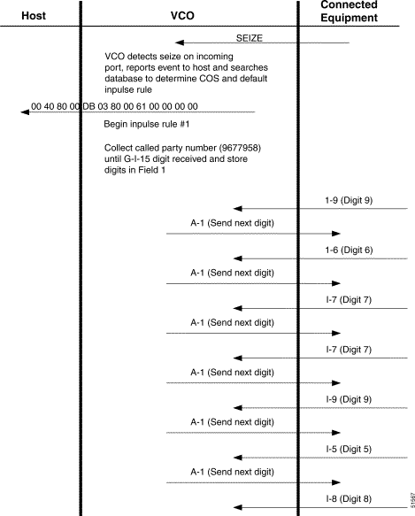
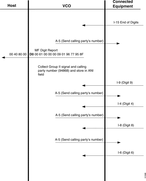
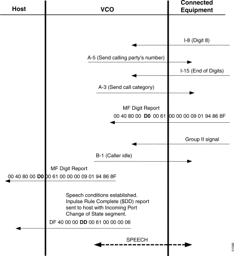
Example #1 illustrates a simple R2 digit collection scenario after an incoming seize on the E1 circuit at port address $00 61. An Argentina 2 inpulse rule is executed to perform R2 digit collection on this circuit.
The inpulse rule performs the following general tasks.
At the end of this example, the VCO/4K establishes speech conditions with the connected equipment (network register) and generates an Inpulse Rule Complete ($DD) report to the host. The processing flow for this example is shown in Figure 4-1 to Figure 4-3. In this example, the Argentina 2 inpulse rule for the incoming circuit is defined as inpulse rule #1 (shown below).
Inpulse Rule #1
Refer to the Cisco VCO/4K System Administrator's Guide for more information about MFCR2-specific inpulse rule tokens.
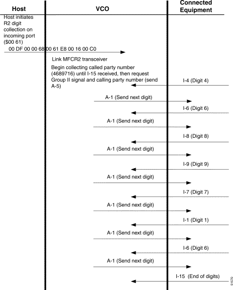
Example #2 also illustrates a simple R2 digit collection scenario on an incoming E1 circuit (port address $00 61). However, all R2 digit collections in this scenario are initiated by host command; no inpulse rule processing is used. Three MF Collection Control ($68) commands perform the following actions:
An MF Digit ($D0) report reports each digit collection to the host.
At the end of this example, the VCO establishes speech conditions with the connected equipment (network register). The processing flow for this example is shown in Figure 4-4 to Figure 4-6.
Refer to the Cisco VCO/4K Standard Programming Reference and the Cisco VCO/4K Extended Programming Reference for complete descriptions of the $68 command and $D0 report.


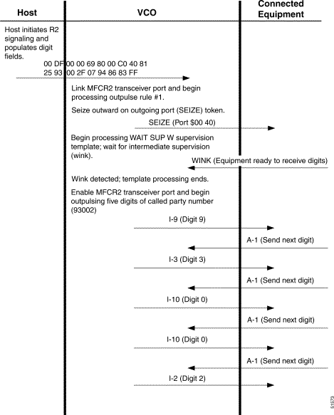
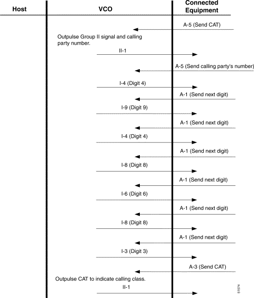
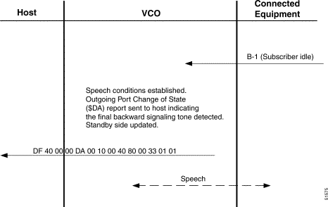
Example #3 describes R2 digit outpulsing on an E1circuit at port address $00 40. This scenario involves both host command and outpulse rule processing. The host initiates the outpulsing with an Outgoing Port Control ($69) command that populates the digit fields and specifies the outpulse rule to execute (refer to the Cisco VCO/4K Standard Programming Reference and the Cisco VCO/4K Extended Programming Reference for a command description).
The outpulse rule performs the following actions:
This rule is shown below.
Outpulse Rule #1
At the end of this example, the VCO establishes speech conditions with the connected equipment (network register) and generates an Outgoing Port Change of State ($DA) report to the host indicating the final backward digit. The processing flow for this example is shown in Figure 4-7 to Figure 4-9.
Refer to the Cisco VCO/4K System Administrator's Guide for more information about OP MFCR2, OP ANI, OP FIELD [xx], and OP CAT [xx] outpulse rule tokens.
![]()
![]()
![]()
![]()
![]()
![]()
![]()
![]()
Posted: Sat Sep 28 19:05:56 PDT 2002
All contents are Copyright © 1992--2002 Cisco Systems, Inc. All rights reserved.
Important Notices and Privacy Statement.