|
|

This publication includes two chapters that address the International Organization for Standardization (ISO) Connectionless Network Services (CLNS) protocol, which is a standard for the Network Layer of the Open Systems Interconnection (OSI) model. This chapter focuses on the following topics:
Commands discussed in this chapter are summarized at the end for this chapter. See the chapter "ISO CLNS Routing Protocols" for information on the various routing protocols and how they are used in internetworks.
The Cisco routing software supports packet forwarding and routing for ISO CLNS on networks using a variety of data link layers: Ethernet, Token Ring, FDDI, and serial.
You can use CLNS routers on serial interfaces with HDLC, LAPB, X.25, SMDS, or Frame Relay encapsulation. To use HDLC encapsulation, you must have a Cisco router at both ends of the link. If you use X.25 encapsulation, you must manually enter the NSAP-to-X.121 mapping. The LAPB, SMDS, Frame Relay, and X.25 encapsulations will interoperate with other vendors.
In addition, the Cisco CLNS implementation is compliant with the Government Open Systems Interconnection Profile (GOSIP) Version 2.
As part of its CLNS support, Cisco routers fully support these ISO and ANSI standards:
Cisco supports both the ISO-developed IS-IS and Cisco's ISO Interior Gateway Routing Protocol (ISO-IGRP) dynamic routing protocols for dynamic routing of ISO CLNS.
In addition, Cisco supports static routing for ISO CLNS.
Support for IS-IS, ISO-IGRP, and static routing are described in the chapter "ISO CLNS Routing Protocols."
In this publication, switching involves taking a packet in one interface and sending it out another (or the same) interface. Switching decisions are always made by looking in a table. If the routing table is built dynamically, the process that does so implements a routing protocol. If the routing table is built by user configuration, the router is doing static routing.
When configured for switching only, the router makes only forwarding decisions. It does not perform other routing-related functions. In such a configuration, the router compiles a table of adjacency data, but does not advertise this information. The only information that is inserted into the routing table is the NSAP and Network Entity Title (NET) addresses of this router, static routes, and adjacency information.
The ISO network architecture uses terminology and concepts that differ from IP networks. In other network architectures, CLNS would be known as a datagram service; in the TCP/IP architecture, for example, datagram service is provided by IP.
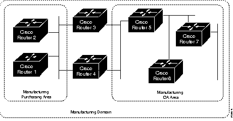
The lowest level of the routing hierarchy is the area--a set of end systems connected by intermediate systems (routers). See Figure 1-1. The network itself has no separate identity, no network number; instead, the next addressable entity above the end system or intermediate system (router) is the area.
Areas are connected to other areas to form routing domains. Each domain is a separately administered region, similar in concept to an autonomous system in IP networks.
Some intermediate systems keep track of how to communicate with all of the End Systems in their area, and thereby function as local routers (sometimes referred to as Level 1 routers). Other intermediate systems keep track of how to communicate with other areas in the domain, functioning as area routers (sometimes referred to as Level 2 routers). Cisco routers are always local and area routers when routing ISO-IGRP; Cisco routers can be configured to be local only, area only, or both local and area routers when routing IS-IS.
End systems communicate with intermediate systems using the ES-IS protocol. Level 1 and Level 2 intermediate systems communicate with each other using either ISO IS-IS or Cisco's ISO-IGRP protocol.
Routing across domains (inter-domain routing) may be done either statically or dynamically (with ISO-IGRP).
Specific ISO CLNS routing protocols supported by Cisco are discussed in the chapter "ISO CLNS Routing Protocols."
Various CLNS configuration commands allow the use of a name to represent a full NSAP or NET. When names are used in this way, the following system behaviors occur:
router iso-igrp
net cisco
Follow these steps to configure your router to support ISO CLNS:
Step 1: Enable CLNS routing with the clns routing global configuration command.
Step 2: Create dynamic routing processes with the router global configuration command and either the iso-igrp or isis keywords. You do not need to explicitly specify a routing process to use static routing facilities. Refer to the chapter "ISO CLNS Routing Protocols" for more information about static and dynamic routing.
Step 3: Specify which interface should be actively routing ISO CLNS with the clns router interface subcommand.
If you do not intend to use a dynamic routing protocol on a specific interface, but wish to switch packets over the link, use the clns enable interface subcommand.
These steps enable CLNS routing. Optional commands are also available for customizing the environment, and you may follow these steps to complete configuration:
Step 1: Configure static information, such as prefix routes and/or NSAP to media address mappings.
Step 2: Adjust ES-IS parameters, as necessary.
Each task is described in the following sections or in the chapter "ISO CLNS Router Protocols" (routing protocol specifics). Configuration information is followed by descriptions of the EXEC commands to maintain, monitor and debug the ISO CLNS network. Summaries of the global configuration commands and interface subcommands described in these sections appear at the end of this chapter.
Addresses in the ISO network architecture are referred to as Network Entity Titles (NETs) and Network Service Access Points (NSAPs). Each node in an ISO network has one or more NETs. In addition, each node has many NSAPs. Each NSAP differs from one of the NETs for that node in only the last byte. This byte is called the n-selector. See Figure 1-2 . Its function is similar to the port number in other protocol suites.
Cisco's implementation supports all NSAPs that are defined by ISO 8348/Ad2; however, Cisco only provides dynamic routing (ISO-IGRP or IS-IS routing), for NSAPs that conform to the address constraints defined in the ISO standard for IS-IS (ISO 10589). Figure 1-2 and Figure 1-2 illustrate the conforming NSAP addresses.
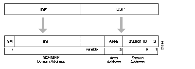
The fields that comprise an ISO-IGRP NSAP are defined as follows:
Cisco's ISO-IGRP CLNS-routing implementation interprets the bytes from the AFI up to (but not including) the Area field in the DSP as a domain identifier. The Area field specifies the area, and the station ID specifies the station.
The domain address uniquely identifies the routing domain. Within each routing domain, you can set up one or more areas. The area address uniquely identifies the area.
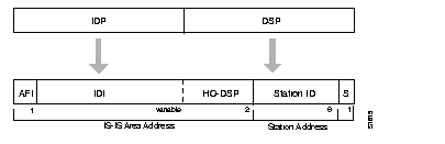
The fields that comprise an IS-IS packet are defined as follows:
Cisco's ISO IS-IS CLNS-routing implementation interprets the bytes from the AFI up to (but not including) the station ID field in the DSP as an area identifier. The station ID specifies the station.
The area address uniquely identifies the routing area. Within each routing domain you can set up one or more areas. The area address uniquely identifies the area.
The key difference between these two addressing schemes is in the definition of area addresses. Both use the station ID for Level 1 routing.
However, they differ in the way addresses are specified for area routing. An ISO-IGRP NSAP address includes three separate levels for routing: the domain, area, and, station ID. An IS-IS address includes two fields: a single continuous area field comprised of the domain and area fields defined for ISO-IGRP and the station ID.
All NSAPs must obey the following constraints:
The following are examples of OSInet and GOSIP NSAPs, using ISO-IGRP implementation:
OSInet:
47.0004.004D.0003.0000.0C00.62E6.00
|     Domain|Area|    Station ID| S|
GOSIP Network:
47.0005.80FF.FF00.0000.FFFF.0004.0000.0C00.62E6.00
|             Domain       |Area|  Station ID  | S|
The area addressing scheme allowed in IS-IS routing supports assignment of multiple area addresses. Multiple area addresses are assigned statically on the router with the net router subcommand defined in the next chapter. Cisco currently supports assignment of up to three area addresses.
Multihoming provides a mechanism for smoothly migrating network addresses:
A Cisco router can dynamically learn about any adjacent router. As part of this process, the routers inform each other of their area addresses. If two routers share at least one area address, the set of area addresses of the two routers are merged. The merged set may not contain more than three addresses. If there are more than three, the addresses with the lowest numerical values are kept, and all others are dropped.
The following example net commands illustrate assignment of three separate area addresses for a single router:
router isis eng-area1
net 47.0004.004D.0001.0000.0C00.1111.00
net 47.0004.004D.0002.0000.0C00.1111.00
net 47.0004.004D.0003.0000.0C00.1111.00
!  |    IS-IS Area  |    Station ID| S|
The result is that traffic received that includes an area address of 47.0004.004D.0001, 47.0004.004D.0002, or 47.0004.004D.0003, and that has the same station ID, will be forwarded to destination station in eng-area1.
Conceptually, each End System (ES) lives in one area. It discovers the nearest Level 1 IS (router) by listening to ES-IS packets. Each ES must be able to communicate directly with a Level 1 IS in its area.
When an ES wants to communicate with another ES, it sends the packet to the Level 1 IS for its area. The IS will look up the destination NSAP and forward the packet along the best route. If the destination NSAP is for an ES in another area, the Level 1 IS will send the packet to the nearest Level 2 IS. The Level 2 IS will forward the packet along the best path for the destination area until it gets to a Level 2 IS which is in the destination area. This IS will forward the packet along the best path inside the area until it is delivered to the destination ES.
The configuration process begins with enabling CLNS routing. Enable CLNS routing with the clns routing global configuration command. The full syntax for this command follows.
clns routingUse the no clns routing command to disable CLNS routing.
You need to decide now if you want to use static or dynamic routing. Static routing is required if you must interoperate with another vendor's equipment that does not support IS-IS. In addition, static routing is generally preferable for operation over X.25, Frame Relay, or SMDS networks.
You must also enable ISO CLNS for each interface. This is automatically done when configuring IS-IS or ISO-IGRP routing on an interface; however, if you do not intend to perform any dynamic routing on an interface, but intend to pass ISO CLNS packet traffic to end systems, use the clns enable interface subcommand. The syntax for this command is as follows:
clns routingUse the no clns enable command to disable ISO CLNS on a particular interface.
X.25 is not a broadcast medium, and therefore ES-IS is not generally used to automatically advertise and record NSAP/NET (protocol address) to SNPA (media address) mappings. Operation of CLNS over X.25 requires that this mapping information be statically entered using the clns is-neighbor and/or the clns es-neighbor interface subcommands.
Configuring a serial line to use CLNS over X.25 requires configuring the general X.25 information and the CLNS-specific information. The general X.25 information must be configured first. Then, the clns is-neighbor and clns es-neighbor interface subcommands are issued to list all the Intermediate and End Systems that will be used. Full command syntax for these commands follows.
clns es-neighbor nsap snpa [X.25-facilities-info]In this case, the Subnetwork Points of Attachment (SNPAs) are the X.25 network addresses (X.121 addresses). These are usually assigned by the X.25 network provider. Use the argument X.25-facilities-info to specify nondefault packet and window size, reverse charge information, and so on. Refer to the chapter "Configuring Packet-Switched Software" for more information.
This command maps NSAP 47.0004.004d.0001.3132.3334.3536.00 to X.121 address 310117.
clns es-neighbor 47.0004.004d.0001.3132.3334.3536.00 310117
Only one es-neighbor or one is-neighbor entry can be made for each X.121 address.
The X.25 facilities information that can be specified is exactly the same as in the x25 map subcommand described in the section "Setting Address Mappings" in the chapter "Configuring Packet-Switched Software."
You can specify the following information:
Following is a more complicated example that specifies nondefault packet and window size:
clns is-neighbor 47.0004.004d.0001.3132.3344.3535.00 310117 windowsize 7 7
packetsize 512 512
The system does not accept an X.25 call unless the source of the call has been configured as an ES or IS neighbor in the destination router. The system will not accept a call requesting reverse charges unless the keyword accept-reverse is used as follows.
clns is-neighbor 47.0004.004d.0001.1112.1314.1516.00 310120249 accept-reverse
All of the information that is entered using the clns is-neighbor and clns es-neighbor subcommands actually goes into two places in the system: the adjacency table and the X.25 map table. The adjacency table stores only the NSAP/NET and X.121 address information. The X.25 map table stores this information but also stores the facility information. If a virtual circuit (VC) has been established, the logical channel numbers (LCNs) in use are shown.
This section describes the commands used to configure the ES-IS parameters for host-router communication. In general, however, these should be left at their default values.
When configuring an ES-IS router, be aware that:
The clns configuration-time global configuration command specifies the rate at which ESH and ISH packets are sent.
clns configuration-time secondsThe default value for seconds is 60, and this value is restored by the no clns configuration-time command.
The clns holding-time subcommand allows the sender of an ESH or ISH to specify the length of time during which the information in the Hello packets will be believed.
clns holding-time secondsThe argument seconds specifies the time in seconds. The default value is 300 seconds (five minutes), which is restored by the no clns holding-time command.
End Systems need to know how to get to a Level 1 IS for their area and Level 1 ISs need to know all of the ESs that are directly reachable through each of their interfaces. To provide this information, Cisco routers support the ES-IS protocol. A Cisco router dynamically discovers all ESs running the ES-IS protocol. ESs which are not running the ES-IS protocol must be statically configured. This is done using the clns es-neighbor interface subcommand:
clns es-neighbor nsap snpaThe argument nsap specifies the CLNS address. The argument snpa specifies the data link address. The no keyword deletes the ES neighbor. If you have configured the clns router iso-igrp or clns router isis subcommand for a particular interface, the Cisco ES-IS routing software automatically turns ES-IS on for that interface.
It is sometimes desirable for a router to have a neighbor entry statically configured rather than learned through ES-IS, ISO-IGRP or IS-IS. The clns is-neighbor interface subcommand enters an IS neighbor.
clns is-neighbor nsap snpaThe argument nsap specifies the NSAP address. The argument snpa specifies the data link address. The no clns is-neighbor command deletes the specified IS neighbor.
If there are systems on the Ethernet that do not use ES-IS, or if X.25 is being used, NSAP/NET (protocol address) to SNPA (media address) mappings must be specified using the clns is-neighbor and/or the clns es-neighbor interface subcommands.
An example of configuring an Ethernet interface with the Ethernet address (MAC address) of systems that do not use ES-IS follows.
interface ethernet 0
clns es-neighbor 47.0004.004D.0055.0000.0C00.A45B.00  0000.0C00.A45B
In this case, the End Systems with the NSAP (or NET) listed below is configured at an Ethernet MAC address of 0000.0C00.A45B.
47.0004.004D.0055.0000.0C00.A45B.00
Generally, you do not need to change the default settings for CLNS packet switching, but there are some modifications you can make when you decide that it is advantageous.
All interfaces have a default maximum packet size. You can set the maximum transmission unit (MTU) size of the packets sent on the interface using the clns mtu interface subcommand. The full syntax of this command follows.
clns mtu sizeThe minimum value for the size argument is 512; the default and maximum packet size depends on the interface type. The default value is restored by the no clns mtu command.
When the ISO CLNS routing software sources a CLNS packet, by default it generates checksums. The clns checksum interface subcommand specifies this function. Use the no clns checksum command to disable checksum generation.
clns checksumThe clns route-cache interface subcommand allows fast switching through the cache, and by default, is enabled. To disable fast switching, use the no clns route-cache command.
clns route-cacheIf a router configured for CLNS experiences congestion, it sets the congestion experienced bit. The congestion threshold is a per-interface parameter set by the clns congestion-threshold interface subcommand. The full syntax for this command follows.
clns congestion-threshold numberThis subcommand causes the system to set the congestion-experience bit if the output queue has more than the specified number of packets in it. A number value of zero or the no keyword prevents this bit from being set. The default value for number is 4.
Use the no clns congestion-threshold command with the appropriate value to remove the parameter setting.
When a CLNS packet comes in, the routing software looks in the routing table for the next hop. If it does not find the next hop, the packet is discarded and an error Protocol Data Unit (ERPDU) may be sent.
The clns send-erpdu interface subcommand allows CLNS to send an error PDU when it detects an error in a data PDU, and by default, is enabled. To disable this function, use the no clns send-erpdu command. The syntax for both commands follows.
clns send-erpduThe clns erpdu-interval interface subcommand determines the minimum interval time, in milliseconds, between ERPDUs. The full syntax of this command follows.
clns erpdu-interval millisecondsA milliseconds value of zero or the no clns erpdu-interval command turns off the interval rate and effectively sets no limit to the ERPDU rate. The default rate is once every ten milliseconds.
The clns erpdu-interval subcommand will not send ERPDUs more frequently than one per interface per ten milliseconds.
If a packet is sent out the same interface it came in on, a redirect PDU (RDPDU) may also be sent to the sender of the packet. The clns send-rdpdu interface subcommand allows CLNS to send redirect PDUs when a better route for a given host is known, and this is the default behavior. The full syntax of the command follows.
clns send-rdpduTo disable this function, use the no clns send-rdpdu command.
An RDPDU may be disabled on a per-interface basis using the clns rdpdu-interval interface subcommand. The full syntax of the command follows.
clns rdpdu-interval millisecondsThe command determines the minimum interval time, in milliseconds, between RDPDUs. A milliseconds value of zero or the no clns rdpdu-interval command turns off the interval rate and effectively sets no limit to the RDPDU rate. The default rate is once every 100 milliseconds. An RDPDU is rated-limited, and is not sent more frequently than one per interface, per 100 milliseconds.
The address mask is normally present on all RDPDUs, but can be disabled with the no clns rdpdu-mask interface subcommand. The full syntax of the clns rdpdu-mask command follows.
clns rdpdu-maskUse these commands to configure parameters for packets sourced by this router. Full command syntax for each command is listed with the descriptions. The no forms of the commands remove the parameter's settings.
The clns packet-lifetime global configuration command specifies the initial lifetime for locally generated packets.
clns packet-lifetime numberThe default value for number is 64.
The clns want-erpdu interface subcommand specifies whether to request error PDUs on packets sourced by the router.
clns want-erpduThe default is to request error PDUs.
The ISO CLNS routing software ignores the Record Route option, the Source Route option, and the QOS (quality of service) option other than congestion experienced. The security option causes a packet to be rejected with a bad option indication.
The clns host global configuration command can be useful for creating a name for an NSAP. This name can then be used in place of typing the long set of numbers associated with an NSAP. The command syntax follows.
clns host name nsapThe argument name is the desired name for the NSAP, which is specified by the nsap argument. The first character of the name argument must be a letter; it cannot be a digit.
The clns net command can be used as either a global configuration command or as an interface subcommand to assign static addresses. The following brief descriptions explain these two uses.
If a router is configured to support ISO CLNS, but is not configured to dynamically route CLNS packets using ISO-IGRP or IS-IS, use the clns net command to assign an address to the router. The command syntax follows:
clns net NET-addressThere is no default for this address.
The argument NET-address is an NET.
A CLNP packet sent to any of the defined NSAPs or NETs will be received by the router. The router chooses the NET to use when it sends a packet with the following algorithm:
The no clns net command removes the NET or NSAP address.
The clns net command can also be used as a configuration interface subcommand for assigning an NSAP address for a specific interface. The command syntax is:
clns net {NSAP-address|name}The argument NSAP-address is an NSAP address; the argument name is a name to be associated with this interface. Either can be used.
The no clns net command removes the NSAP address. This command is useful if you are doing static routing and need to control the source NET used by the router on each interface.
The clns dec-compatible command is useful in old DEC implementations of ES-IS in which the NSAP address advertised in an ISH does not have the N-selector byte present. (This is the last byte of the NSAP address.) This command has the following syntax:
clns dec-compatibleWhen the clns dec-compatible command is set, ISHes sent and received ignore the N-selector byte.
DECnet Phase V cluster aliasing allows multiple systems to advertise the same System id in end-system Hello messages. The router does this by caching multiple ES adjacencies with the same NSAP, but different SNPA addresses. When a packet is destined to the common NSAP address, the router load-splits the packets among the different SNPA addresses. A router that supports this capability forwards traffic to each individual system.
The clns cluster-alias interface subcommand enables this on a per interface basis. The command syntax is:
clns cluster-aliasIf DECnet Phase V cluster aliases are disabled on an interface, End-System Hello packet information is used to replace any existing adjacency information for the NSAP. Otherwise, an additional adjacency (with a different SNPA) is created for the same NSAP.
! Enable cluster aliasing for CLNS
!
clns nsap 47.0004.004d.0001.0000.0c00.1111.00
clns routing
interface Ethernet 0
clns cluster-alias
interface Ethernet 1
clns cluster-alias
Use the EXEC commands described in this section to maintain the ISO CLNS caches, tables, and databases.
The EXEC command clear clns cache clears and reinitializes the CLNS routing cache.
The command clear clns route removes all of the dynamically derived CLNS routing information.
The command clear clns neighbors removes CLNS neighbor information from the adjacency database.
The command clear clns es-neighbors removes ES neighbor information from the adjacency database.
The command clear clns is-neighbors removes IS neighbor information from the adjacency database.
Use the EXEC commands described in this section to obtain displays of activity on the ISO CLNS network.
The show clns command displays information about the CLNS network. Enter this command at the EXEC prompt:
show clnsSample output follows.
  Global CLNS Information:
  2 Interfaces Enabled for CLNS
  NET: 39.0004.0030.0000.0C00.224D.00
  NET: 39.0003.0020.0000.0C00.224D.00
  Configuration Timer: 60, Default Holding Timer: 300, Packet Lifetime 64
  ERPDU's requested on locally generated packets
  Intermediate system operation enabled (forwarding allowed)
  ISO-IGRP level-1 Router: remote
    Routing for Domain: 39.0003, Area: 0020
  ISO-IGRP level-2 Router: DOMAIN_remote
    Routing for Domain: 39.0003
  IS-IS level-1-2 Router:
    Routing for Area: 39.0004.0030
In the display:
Use the EXEC command show clns cache to display the CLNS routing cache. Enter this command at the EXEC prompt:
show clns cacheThe cache contains an entry for each destination that has packet switching enabled.
Following is sample output:
CLNS routing cache version 433
Destination -> Next hop @ Interface : SNPA Address
*39.0004.0040.0000.0C00.2D55.00
  -> 0000.0C00.2D55 @ Serial2
 39.0003.0020.0000.0C00.3E51.00
  -> 0000.0C00.3E51 @ TokenRing1 : 0000.3000.5475
In the display, there will be an entry in the cache specifying each destination for which the Cisco router has switched a packet in the recent past. This includes the Cisco router. Each entry has the following format:
destination ' first hop address@interface:MAC-layer address
Use the show clns traffic command to list the CLNS packets this router has seen. Enter this command at the EXEC prompt:
show clns trafficSample output follows:
CLNS & ESIS Output: 139885, Input: 90406
CLNS Local: 0, Forward: 0
CLNS Discards:
  Hdr Syntax: 150, Checksum: 0, Lifetime: 0, Output cngstn: 0
  No Route: 0, Dst Unreachable 0, Encaps. Failed: 0
  NLP Unknown: 0, Not an IS: 0
CLNS Options: Packets 19, total 19, bad 0, GQOS 0, cngstn exprncd 0
CLNS Segments:  Segmented: 0, Failed: 0
CLNS Broadcasts: sent: 0, rcvd: 0
Echos: Rcvd 0 requests, 69679 replies
      Sent 69701 requests, 0 replies
ESIS(sent/rcvd): ESHs: 0/34, ISHs: 483/1839, RDs: 0/0, QCF: 0/0
ISO-IGRP: Querys (sent/rcvd): 0/0 Updates (sent/rcvd): 1279/1402
ISO-IGRP: Router Hellos: (sent/rcvd): 1673/1848
ISO-IGRP Syntax Errors: 0
IS-IS: Level-1 Hellos (sent/rcvd): 0/0
IS-IS: Level-2 Hellos (sent/rcvd): 0/0
IS-IS: PTP Hellos     (sent/rcvd): 0/0
IS-IS: Level-1 LSPs   (sent/rcvd): 0/0
IS-IS: Level-2 LSPs   (sent/rcvd): 0/0
IS-IS: Level-1 CSNPs  (sent/rcvd): 0/0
IS-IS: Level-2 CSNPs  (sent/rcvd): 0/0
IS-IS: Level-1 PSNPs  (sent/rcvd): 0/0
IS-IS: Level-2 PSNPs  (sent/rcvd): 0/0
IS-IS: Level-1 DR Elections: 0
IS-IS: Level-2 DR Elections: 0
IS-IS: Level-1 SPF Calculations: 0
IS-IS: Level-2 SPF Calculations: 0
In the display:
Output field) and received (the Input field).
The show clns redirects command displays CLNS redirect information. Enter this command at the EXEC prompt:
show clns redirectsOnly ESs maintain redirect information.
The show clns interface command lists the CLNS-specific information about each interface, and is entered at the EXEC prompt, as follows:
show clns interface [interface unit]Following is sample output illustrates information displayed for Token Ring and Serial interfaces:
TokenRing 0 is administratively down, line protocol is down
  CLNS protocol processing disabled
 --More--
TokenRing 1 is up, line protocol is up
  Checksums enabled, MTU 4461, Encapsulation SNAP
  ERPDUs enabled, min. interval 10 msec.
  RDPDUs enabled, min. interval 100 msec., Addr Mask enabled
  Congestion Experienced bit set at 4 packets
  CLNS fast switching disabled
  DEC compatibility mode OFF for this interface
  Next ESH/ISH in 18 seconds
  Routing Protocol: ISO-IGRP
    Routing Domain/Area: <39.0003> <0020>
 --More--
Serial 2 is up, line protocol is up
  Checksums enabled, MTU 1497, Encapsulation HDLC
ERPDUs enabled, min. interval 10 msec.
  RDPDUs enabled, min. interval 100 msec., Addr Mask enabled
  Congestion Experienced bit set at 4 packets
  CLNS fast switching enabled
  DEC compatibility mode OFF for this interface
  Next ESH/ISH in 48 seconds
  Routing Protocol: IS-IS
    Circuit Type: level-1-2
    Level-1 Metric: 10, Priority: 64, Circuit ID: 0000.0C00.2D55.0A
    Level-2 Metric: 10, Priority: 64, Circuit ID: 0000.0000.0000.00
In the display:
The show clns neighbors command displays both ES and IS neighbors. Enter this command at the EXEC prompt:
show clns neighbors [interface-type unit] [detail]The interface-type and unit optional arguments specify a specific interface to be displayed. If detail is specified, the area addresses advertised by the neighbor in the Hello messages is displayed. Otherwise, a summary display is provided. This display is a composite of the show clns es-neighbor and show clns is-neighbor commands.
Sample output follows:
System Id       SNPA             Interface   State  Holdtime  Type  Protocol
0000.0000.0007  aa00.0400.6408   Ethernet0   Init   277       IS    ES-IS
0000.0C00.0C35  0000.0c00.0c36   Ethernet1   Up     91        L1    IS-IS
0800.2B16.24EA  aa00.0400.2d05   Ethernet0   Up     29        L1L2  IS-IS
0800.2B14.060E  aa00.0400.9205   Ethernet0   Up     1698      ES    ES-IS
0000.0C00.3E51  *HDLC*           Serial1     Up     28        L2    IS-IS
0000.0C00.62E6  0000.0c00.62e7   Ethernet1   Up     22        L1    IS-IS
AA00.0400.2D05  aa00.0400.2d05   Ethernet0   Init   24        IS    ES-IS
The following fields are provided in this display:
Init--The system is an IS and is waiting for an IS-IS Hello message. IS-IS regards the neighbor as not adjacent.
Up--Believes the ES or IS is reachable.
ES--An end-system adjacency either discovered via the ES-IS protocol or statically configured.
IS--A router adjacency either discovered via the ES-IS protocol or statically configured.
L1--A router adjacency for Level-1 routing only.
L1L2--A router adjacency for Level-1 and Level-2 routing.
L2--A router adjacency for Level-2 only.
A sample output of the show clns neighbors detail command follows:
System Id       SNPA             Interface   State  Holdtime  Type  Protocol
0000.0000.0007  aa00.0400.6408   Ethernet0   Init   291       IS    ES-IS
  Area Address(es): 47.0005.80FF.F500.0000.0003.0020
0000.0C00.0C35  0000.0c00.0c36   Ethernet1   Up     94        L1    IS-IS
  Area Address(es): 47.0004.004D.0001 39.0001
0800.2B16.24EA  aa00.0400.2d05   Ethernet0   Up     9         L1L2  IS-IS
  Area Address(es): 47.0004.004D.0001
0800.2B14.060E  aa00.0400.9205   Ethernet0   Up     1651      ES    ES-IS
  Area Address(es): 49.0040
0000.0C00.3E51  *HDLC*           Serial1     Up     27        L2    IS-IS
  Area Address(es): 39.0004
0000.0C00.62E6  0000.0c00.62e7   Ethernet1   Up     26        L1    IS-IS
  Area Address(es): 47.0004.004D.0001
AA00.0400.2D05  aa00.0400.2d05   Ethernet0   Init   29        IS    ES-IS
  Area Address(es): 47.0004.004D.0001
In addition to the information displayed in show clns neighbors, this show command displays the area addresses associated with the adjacencies.
The show clns is-neighbors command displays neighbor entries sorted according to the area in which they are located. Enter this command at the EXEC prompt:
show clns is-neighbors [interface-type unit] [detail]The interface-type and unit optional arguments specify an interface to be displayed. If detail is specified, the areas associated with Intermediate Systems are displayed. Otherwise, a summary display is provided. Following is sample output:
System Id       Interface   State  Type  Priority  Circuit Id         Format
0000.0C00.0C35  Ethernet1   Up     L1    64        0000.0C00.62E6.03  Phase V
0800.2B16.24EA  Ethernet0   Up     L1L2  64/64     0800.2B16.24EA.01  Phase V
0000.0C00.3E51  Serial1     Up     L2    0         04                 Phase V
0000.0C00.62E6  Ethernet1   Up     L1    64        0000.0C00.62E6.03  Phase V
This display presents IS-IS related information for IS-IS router adjacencies. The following fields are provided in this display:
Up and Init are the states. See the show clns neighbors description.
A sample output of the show clns is-neighbors detail command follows:
System Id       Interface   State  Type  Priority  Circuit Id         Format
0000.0C00.0C35  Ethernet1   Up     L1    64        0000.0C00.62E6.03  Phase V
  Area Address(es): 47.0004.004D.0001 39.0001
0800.2B16.24EA  Ethernet0   Up     L1L2  64/64     0800.2B16.24EA.01  Phase V
  Area Address(es): 47.0004.004D.0001
0000.0C00.3E51  Serial1     Up     L2    0         04                 Phase V
  Area Address(es): 39.0004
0000.0C00.62E6  Ethernet1   Up     L1    64        0000.0C00.62E6.03  Phase V
  Area Address(es): 47.0004.004D.0001
In addition to the information displayed in show clns is-neighbors, this show command displays the area addresses associated with the adjacencies.
The show clns es-neighbors command lists the ES neighbors that this router knows about. Enter this command at the EXEC prompt:
show clns es-neighbors [interface-type unit] [detail]The interface-type and unit optional arguments specify an interface to be displayed. If detail is specified, the areas associated with the End Systems are displayed. Otherwise, a summary display is provided. Following is sample output:
System Id       Interface   State  Type  Format
0800.2B14.060E  Ethernet0   Up     ES    Phase V
0800.2B14.0528  Ethernet0   Up     ES    Phase V
This displays end-system adjacencies. See the show clns is-neighbors command for field descriptions.
A sample output of the show clns es-neighbors detail command follows:
System Id       Interface   State  Type  Format
0800.2B14.060E  Ethernet0   Up     ES    Phase V
  Area Address(es): 49.0040
0800.2B14.0528  Ethernet0   Up     ES    Phase V
  Area Address(es): 49.0040
In addition to the information displayed in show clns es-neighbors, this show command displays the area addresses associated with the adjacencies.
The OSI Connectionless Network Protocol (ISO 8473) does not specify a network-level echo protocol. The Internet Engineering Task Force (IETF) has specified and proposed such a protocol in RFC 1139. Cisco has implemented this specification using the proposed new PDU types Echo Request (1E) and Echo Reply (1F). Non-Cisco routers may or may not forward these packets, depending on whether they are specific about the packet types they will forward. End Systems may not recognize these packets, but will typically generate an error packet (ERPDU) as a response. This ERPDU is useful, as it confirms the reachability of the end system. Table 1-1 lists the characters displayed during the ping test and their meaning.
| Char | Meaning |
|---|---|
| ! | Each exclamation point indicates receipt of a reply. |
| . | Each period indicates the network server timed out while waiting for a reply. |
| U | A destination unreachable error PDU was received. |
| C | A congestion experienced packet was received. |
| I | User interrupted test. |
| ? | Unknown packet type. |
| & | Packet lifetime exceeded. |
The output concludes with the success rate and minimum, average, and maximum round-trip times. To abort a ping session, type the escape sequence (by default, type Ctrl-^, X, which is done by simultaneously pressing the Ctrl, Shift, and 6 keys, letting go then pressing the x key).
The following example uses a name to specify the source.
Protocol [ip]: clns
Target CLNS address: thoth
Repeat count [5]:
Datagram size [100]:
Timeout in seconds [2]:
Type escape sequence to abort.
Sending 5, 100-byte CLNS Echos to 55.0006.0100.0000.0000.0001.8888.1112.1314.151
6.00, timeout is 2 seconds:
!!!!!
Success rate is 100 percent, round-trip min/avg/max = 112/113/116 ms
In this example, an NET address is specified.
Protocol [ip]: clns
Target CLNS address: 47.0004.0050.0002.0000.0c00.243b.00
Repeat count [5]:
Datagram size [100]:
Timeout in seconds [2]:
Type escape sequence to abort.
Sending 5, 100-byte CLNS Echos to 47.0004.0050.0002.0000.0C00.243B.00, timeout is 2 seconds:
!!!!!
Success rate is 100 percent, round-trip min/avg/max = 1/4/8 ms
The ISO CLNS trace command allows you to discover the path that packets take through your network. It sends ping packets and takes advantage of the ERPDUs that are generated when a packet exceeds its time-to-live (TTL) value. The trace command offers default and settable parameters for specifying a simple or extended trace mode. Enter the following command at the EXEC prompt:
trace [destination]To invoke a simple trace test, enter the destination address or host name on the command line. The default parameters for the appropriate protocol are assumed and the tracing action begins.
To use nondefault parameters and invoke an extended trace test, enter the command without a destination argument. You will be stepped through a dialog to select the desired parameters.
Typing the escape sequence (default, type Ctrl-^, X, which is done by simultaneously pressing the Ctrl, Shift, and 6 keys, letting go then pressing the x key) terminates a trace command.
The trace command works by taking advantage of the error messages generated by routers when a datagram exceeds its time-to-live (TTL) value.
The trace command starts by sending probe datagrams with a TTL value of one. This causes the first router to discard the probe datagram and send back an error message. The trace command sends several probes at each TTL level and displays the round trip time for each.
The trace command sends out one probe at a time. Each outgoing packet may result in one of two error messages. A time exceeded error message indicates that an intermediate router has seen and discarded the probe. A destination unreachable error message indicates that the destination node has received the probe and discarded it because it could not deliver the packet. If the timer goes off before a response comes in, trace prints an asterisk (*).
The trace command terminates when the destination responds, when the maximum TTL was exceeded, or when the user interrupts the trace with the escape sequence. The information is encoded as follows:
hop-count name(nsap) result-of-probe
You may use the trace command to trace routes on a Cisco router configured with the ISO CLNS protocol. When stepping through the trace dialog for CLNS, the following parameters may be specified:
Table 1-2 describes the output.
| Char | Meaning |
|---|---|
| nn msec | For each node, the round-trip time (in nn milliseconds) for the specified number of probes |
| & | A time-to-live-exceeded error PDU was received. |
| U | A destination unreachable error PDU was received. |
| I | The user interrupted the test. |
| * | The probe timed out. |
| C | A congestion experienced packet was received. |
Following is simple trace output.
Protocol [ip]: clns
Target CLNS address: thoth
Timeout in seconds [3]:
Probe count [3]:
Minimum Time to Live [1]:
Maximum Time to Live [30]:
Type escape sequence to abort.
Tracing the route to THOTH (55.0006.0100.0000.0000.0001.8888.1112.1314.1516)
  1 HORUS(55.0006.0100.0000.0000.0001.6666.3132.3334.3536) 32 msec ! 28 msec ! 28 msec !
  2 ISIS(55.0006.0100.0000.0000.0001.7777.2122.2324.2526) 56 msec ! 80 msec ! 56 msec !
  3 THOTH(55.0006.0100.0000.0000.0001.8888.1112.1314.1516) 80 msec ! 80 msec ! 8
This example traces a more complex route.
Protocol [ip]: clns
Target CLNS address: cerdiwen
Timeout in seconds [3]:
Probe count [3]:
Minimum Time to Live [1]:
Maximum Time to Live [30]:
Type escape sequence to abort.
Tracing the route to CERDIWEN (49.BEAD.0000.0C00.40A7.00)
  1 DEMETER(49.BEAD.0000.0C00.40AF.00) 72 msec !
     ARTEMIS(49.BEAD.0000.0C00.2D57.00) 72 msec !
     DEMETER(49.BEAD.0000.0C00.40AF.00) 76 msec !
  2 CERDIWEN(49.BEAD.0000.0C00.40A7.00) 148 msec ! 148 msec ! 144 msec !
The output from the trace command displays information for each probe that it sends out. As you can see, there were two equal cost paths to the destination. The first packet went via Demeter, the second went via Artemis, and the third went via Demeter again.
Use the EXEC commands described in this section to troubleshoot and monitor the ISO CLNS network transactions. For each debug command, there is a corresponding undebug command that turns the message logging off. Generally, you will enter these commands during troubleshooting sessions with Cisco engineers.
The debug clns-esis-events command traces the more unusual ES-IS events, including previously unknown neighbors, neighbors which have aged out, and neighbors which have changed roles (ES to IS, and so on).
The debug clns-esis-packets command traces ES-IS activity, including sending and receiving of ESHs and ISHs, receiving Redirects (RDs), and aging out of ESH/ISH/RD entries.
The debug clns-events command traces the more unusual CLNS events, including packet discards, sending of redirects, and so forth.
The debug clns-packets command causes all CLNS activity to be traced, including forwarding of packets. You can use this to circumvent a potential problem with the ping command in mixed Cisco and nonCisco installations; see "ISO CLNS Ping Command" for more information.
The debug clns-routing command causes all CLNS routing table activity to be traced.
This section provides an alphabetical summary of the ISO CLNS global configuration commands.
[no] clns configuration-time seconds
Specifies the rate at which ESHs and ISHs are sent. The default value for seconds is 60.
[no] clns holding-time seconds
Allows the sender of an ESH or ISH to specify the length of time during which the information in the Hello packets will be believed. The argument seconds specifies the time in seconds. The default value is 300 seconds (five minutes).
clns host name nsap
Defines a name for an NSAP that can then be used in commands requiring NSAPs.
[no] clns net NET-address
Used as a global configuration command to assign a static address for a router. If a router is configured to support ISO CLNS but is not configured to dynamically route CLNS packets using a ISO-IGRP or IS-IS, use this command to assign an address to the router. There is no default for this address. The no clns net command removes any previously configured NET-address.
[no] clns packet-lifetime number
Specifies the initial lifetime for locally generated packets. The default value for number is 64.
[no] clns routing
Enables or disables routing of CLNS packets.
This section provides an alphabetical list of the ISO CLNS interface subcommands.
[no] clns checksum
Enables or disables checksum generation when ISO CLNS routing software sources a CLNS packet. By default, this function is on. Use the no form of the command to disable checksum generation.
[no] clns cluster-alias
Allows multiple systems to advertise the same System id in End-System Hello message by caching multiple ES adjacencies with the same NSAP, but different SNPA addresses. When a packet is destined to the common NSAP address, the router load-splits the packets among the different SNPA addresses. A router that supports this capability forwards traffic to each individual system.
[no] clns congestion-threshold number
Sets the congestion experience bit if the output queue has more than the specified number of packets in it. A number value of zero or the no form of the command prevents this bit from being set. The default value for number is four.
[no] clns enable
If you do not intend to perform any static or dynamic routing on an interface, but intend to pass ISO CLNS packet traffic to end systems, use the clns enable interface subcommand.
[no] clns erpdu-interval milliseconds
Determines the minimum interval time, in milliseconds, between ERPDUs. A milliseconds value of zero or the no form of the command turns off the interval rate and effectively sets no limit to the ERPDU rate. The default rate is once every ten milliseconds.
[no] clns es-neighbor nsap snpa
Lists all End Systems that will be used when mapping information is statically entered. The SNPAs are the MAC addresses.
[no] clns es-neighbor nsap snpa [X.25-facilities-info]
Lists all End Systems that will be used when mapping information is statically entered. The SNPAs are the X.25 network addresses (X.121 addresses). These are usually assigned by the X.25 network provider. Use the argument X.25-facilities-info to specify nondefault packet and window size, reverse charge information, and so on.
[no] clns is-neighbor nsap snpa
Lists all Intermediate Systems that will be used when mapping information is statically entered. The SNPAs are the MAC addresses.
[no] clns is-neighbor nsap snpa [X.25-facilities-info]
Lists all Intermediate Systems that will be used when mapping information is statically entered. The SNPAs are the X.25 network addresses (X.121 addresses). These are usually assigned by the X.25 network provider. Use the argument X.25-facilities-info to specify nondefault packet and window size, reverse charge information, and so on.
[no] clns mtu size
Sets the MTU packet size for the interface. The minimum value for size is 512. The no form of the command restores the default and maximum packet size.
[no] clns net {NSAP-address|name}
Used as an interface subcommand to assign an NSAP address or name to a router interface. If a router is configured to support ISO CLNS, but is not configured to dynamically route CLNS packets using a ISO-IGRP or IS-IS, use this command to assign an address to the router. There is no default for this address. The no clns net command removes any previously configured NSAP-address.
[no] clns rdpdu-interval milliseconds
Determines the minimum interval time, in milliseconds, between RDPDUs. A milliseconds value of zero or the no keyword turns off the interval rate and effectively sets no limit to the RDPDU rate. The default rate is once every 100 milliseconds.
[no] clns rdpdu-mask
Enables or disables the address mask on RDPDUs. The address mask is normally present on all RDPDUs, but may be disabled with the no clns rdpdu-mask command.
[no] clns route-cache
Allows fast switching through the cache, and by default, is enabled. To disable fast switching, use the no keyword.
[no] clns send-erpdu
Allows or prevents CLNS to send an error PDU when it detects an error in a data PDU, and by default, is enabled. To disable this function, use the no keyword.
[no] clns send-rdpdu
Allows or prevents CLNS to send redirect PDUs when a better route for a given host is known, and this is the default behavior. To disable this function, use the no keyword.
[no] clns want-erpdu
Specifies whether to request error PDUs on packets sourced by the router. The default is to request error PDUs.
|
|