|
|

Table Of Contents
DOCSIS Set-Top Gateway for the Cisco CMTS
Prerequisites for DOCSIS Set-Top Gateway
Restrictions for DOCSIS Set-Top Gateway
Restrictions for DSG Issue 0.9
General Restrictions for DSG Issue 1.0
Unicast Restrictions for DSG Issues 0.9 and 1.0
Multicast Restrictions for DSG Issues 0.9 and 1.0
Information About DOCSIS Set-Top Gateway
How to Configure the DOCSIS Set-Top Gateway Feature
Enabling and Configuring the DOCSIS Set-Top Gateway Feature
Configuring IP Multicast Operations
Configuring NAT to Support Unicast Messaging (optional)
Disabling the DOCSIS Set-Top Gateway Feature
Configuring a Standard IP Access List for Packet Filtering (Optional)
Configuring a Standard IP Access List for Multicast Group Filtering (Optional)
Monitoring the DOCSIS Set-Top Gateway Feature
Displaying a DOCSIS Set-Top Gateway Tunnel Configuration
Displaying All DOCSIS Set-Top Gateway Tunnel Configurations
Configuration Examples for DOCSIS Set-Top Gateway
Subinterface Configuration Example
Unicast Messaging Configuration Example
Packet Filtering Access List Configuration Example
IP Multicast Access List Configuration Example
IP Multicast Rate-Limiting Access List Configuration Example
Cisco IOS Release 12.2(15)BC2 System Messages
Cisco IOS Release 12.3(9a)BC2 System Messages
DOCSIS Set-Top Gateway for the Cisco CMTS
This document describes the DOCSIS Set-Top Gateway (DSG) feature with its configuration and monitoring from Issue 0.9 through Issue 1.0 on the Cisco Cable Modem Termination System (CMTS).
DSG is a CableLabs° specification that allows cable headends such as the Cisco CMTS to provide a class of cable services known as out-of-band (OOB) messaging to set-top boxes (STBs) over existing Data-over-Cable Service Interface Specifications (DOCSIS) cable networks. DSG 1.0 allows cable Multi-System Operators (MSOs) and other service providers to combine both DOCSIS and STB operations over a single, open and vendor-independent network without requiring any changes to the existing DOCSIS network infrastructure.
At the time of this Cisco publication, the CableLabs° DOCSIS DSG specification is in the current status of "Issued" as characterized by stability, rigorous review in industry and cross-vendor interoperability. The latest version of this developing specification is available at the following locations:
•
http://www.cablemodem.com/specifications/gateway.html
•
Feature Specifications for DOCSIS Set-Top Gateway
Finding Support Information for Platforms and Cisco IOS Software Images
Use Cisco Feature Navigator to find information about platform support and Cisco IOS software image support. Access Cisco Feature Navigator at http://www.cisco.com/go/fn. You must have an account on Cisco.com. If you do not have an account or have forgotten your username or password, click Cancel at the login dialog box and follow the instructions that appear.
Contents
•
•
•
•
•
•
•
Prerequisites for DOCSIS Set-Top Gateway
General Prerequisites
•
•
•
–
http://www.cablemodem.com/specifications/gateway.html
http://www.opencable.com/downloads/specs/SP-DSG-I01-020228.pdf
IP Multicast Prerequisites
•
•
–
–
–
•
•
•
Tip
Restrictions for DOCSIS Set-Top Gateway
Restrictions for DSG Issue 0.9
Cisco IOS Release 12.2(15)BC2 has the following limitations for DSG Issue 0.9:
•
•
•
•
•
•
•
•
•
•
General Restrictions for DSG Issue 1.0
The following general restrictions apply to DSG Issue 1.0 on Cisco uBR7100 series, Cisco uBR7200 series and Cisco uBR10012 routers and the Cisco IOS 12.3(9a)BC release:
•
•
•
•
•
•
•
•
Unicast Restrictions for DSG Issues 0.9 and 1.0
•
Multicast Restrictions for DSG Issues 0.9 and 1.0
•
•
•
•
Information About DOCSIS Set-Top Gateway
This section describes the DOCSIS Set-Top Gateway feature:
•
Feature Overview
The DOCSIS Set-Top Gateway (DSG) feature allows the Cisco CMTS to provide a class of cable services known as out-of-band (OOB) messaging to set-top boxes (STBs) over existing DOCSIS networks. This allows MSOs and other service providers to combine both DOCSIS and STB operations over one, open, vendor-independent network, without any change to the existing network or cable modems.
Out-of-Band Messaging
Out-of-band (OOB) messages allow network control and management messages to be sent to customer premises equipment (CPE) devices, without interfering with the normal data traffic flow. OOB messages also have an advantage over in-band messages in that OOB messages are not dependent on the type of traffic or applications being sent over the network. This allows new OOB messages to be developed and implemented, without requiring any corresponding changes in the network application software.
Previously, OOB messages have been carried over dedicated channels that use proprietary video standards such as SCTE/DVS-167, SCTE/DVS-178, and DVB-RCCL/DAVIC-RCC. These existing systems have the following limitations:
•
•
•
To respond to these limitations, the CableLabs consortium developed the DSG specification to provide a multi-vendor solution that works with both legacy STB and DOCSIS transport paths. This allows MSOs and other service providers to use their legacy systems and STBs over their existing DOCSIS cable plants, while still preparing for DSG-capable STBs that support applications such as Video-on-Demand (VoD), online gaming and other interactive services.
DSG systems allow a wide variety of OOB messages, such as the following standard messages, in addition to generic and vendor-defined messages:
•
•
•
Basic Structure of a DSG Network
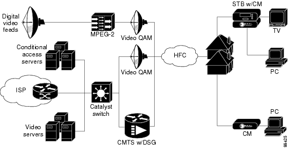
The DOCSIS Set-Top Gateway feature implements the DSG specification on the Cisco CMTS platform, allowing a Cisco CMTS to support both STBs and cable modems over the existing DOCSIS cable network. The CMTS creates a one-way IP datagram channel, called a DSG tunnel, to transport OOB messages to the STBs, allowing the consolidation of cable modem and STB traffic over the same DOCSIS downstream channel.
A typical DSG network contains the following components:
•
•
•
•
•
•
•
The CA servers transmit OOB messages on the network using multicast IP packets, which are received by STBs that are members of the appropriate multicast groups.
Figure 1 shows a typical DSG network.
Figure 1 DSG Network Diagram
Using Point of Deployment Modules and DSG Tunnels
CA vendors typically provide a Point of Deployment (POD) security module to each set-top box customer. Each POD contains a unique ID and a unique X.509 digital certificate that allows the CA/POD vendor's provisioning systems to securely identify and authenticate each set-top box.
Having securely identified and authenticated a set-top box, the CA/POD vendor transmits the OOB messages to the STB over a DSG tunnel, which is an IP multicast datagram stream carried over the DOCSIS downstream channel. Each DSG tunnel is identified by a well-known Ethernet unicast address that is reserved and published by the CA/POD vendor.
The CA/POD vendors can use the different DSG tunnels to provide different services. For example, one CA/POD vendor could define one tunnel for an Electronic Program Guide (EPG), another tunnel for conditional access (CA) programming, a third tunnel for emergency alerts, and a fourth tunnel for software upgrades. Other vendors can define their tunnels in different ways to provide other services.
DSG Addressing
The DOCSIS Set-Top Gateway feature uses the following types of addressing to ensure that the proper OOB messages are delivered to the appropriate STBs:
•
•
The Cisco CMTS router supports an unlimited number of destination multicast addresses, which can be mapped to MAC addresses as follows:
•
•
Note
DSG Operation
DSG maps traffic based on the incoming multicast address or a well-known unicast address. The Cisco CMTS performs the following functions when the CMTS receives an OOB packet from the CA servers over the IP network:
1.
2.
3.
4.
5.
Feature List
Cisco IOS Release 12.3(9a)BC introduces support for DOCSIS Set-Top Gateway (DSG) Issue 1.0 on the following Cisco CMTS platforms:
•
•
•
DSG Issue 1.0 improves upon Issue 0.9 in the following ways:
•
•
•
In Cisco IOS Release 12.2(15)BC2, the DOCSIS Set-Top Gateway feature provides the following features:
•
•
•
•
•
–
–
–
–
–
–
•
•
•
•
•
•
•
Benefits
The DOCSIS Set-Top Gateway feature provides the following benefits to cable MSOs, service providers, and their partners and customers.
Part of CableLabs Specifications
The DOCSIS Set-Top Gateway feature is a CableLabs ( http://www.cablelabs.com) specification allows cable MSOs and service providers to create and deploy new interactive services over existing cable networks. Providers can introduce new services, without impacting their existing customers.
Supports Existing DOCSIS Cable Networks
The DOCSIS Set-Top Gateway feature interoperates with existing DOCSIS-capable networks that can support new interactive services, such as VoD and online gaming, that are expected to become available on cable networks in the future. DOCSIS cable operators can deploy innovative interactive services using the best of the available advanced STB products and middleware and applications software, while still preserving their investment in existing headend systems.
Provides Additional Services
The DOCSIS Set-Top Gateway feature allows cable operators to offer Internet access, e-mail, chat services, and other high-bandwidth services, in addition to the existing STB services (such as EPG and CA). Providers can deliver high-speed data services to their cable TV subscribers using the DOCSIS network.
Provides the Capability to Use Multiple CA/POD Vendors
The DOCSIS Set-Top Gateway feature allows cable operators to offer services from many CA/POD vendors, as opposed to existing networks that typically limit the operator to only one vendor per network. This allows greater flexibility in combining or sharing operations between operators or providers.
Uses Standard DOCSIS Networks
The DOCSIS Set-Top Gateway feature uses existing DOCSIS 1.0, DOCSIS 1.1, and DOCSIS 2.0 networks. MSOs and other service providers can continue to create open-standard, vendor-independent DOCSIS networks, without having to maintain legacy STB systems that could disrupt DOCSIS operations.
Simplifies Network Operations and Cost
MSOs and other service providers can use one simplified return channel architecture to support both STBs and DOCSIS cable modems, instead of using two separate return channels. This lowers the complexity of managing CPE devices and requires less investment in headend equipment, which in turn lowers the overall operations and support costs.
Supports Higher Density of STBs
Depending on the CMTS platform, the higher bandwidth available in DOCSIS networks allows MSOs and other service providers to support a higher maximum number of STBs per headend system.
How to Configure the DOCSIS Set-Top Gateway Feature
See the following sections for how to enable, configure, disable, and monitor the DOCSIS Set-Top Gateway feature:
•
•
•
•
•
•
Note
Router#).
Enabling and Configuring the DOCSIS Set-Top Gateway Feature
This section describes how to enable and configure the DOCSIS Set-Top Gateway on one or more cable interfaces.
SUMMARY STEPS
1.
2.
3.
4.
5.
6.
DETAILED STEPS
Step 1
configure terminal
Example:Router# configure terminal
Router(config)#
Enters global configuration mode.
Step 2
interface cable interface
Example:Router(config)# interface cable 3/0
Router(config-if)#
Enters interface configuration mode for the specified cable interface.
Note
Step 3
cable dsg tunnel-MAC-address group-ip-address CA-vendor-name
Example:Router(config-if)# cable dsg 0010.0025.0025 224.3.3.105 AAARouter(config-if)# cable dsg 0006.0006.0006 224.4.4.1 BBBRouter(config-if)# cable dsg 0010.0001.0001 224.4.4.4 CCCRouter(config-if)#
Configures the cable interface for DSG operations, using the following parameters to create the DSG tunnel:
•
•
•
Note
Step 4
exit
Example:Router(config-if)# exit
Router(config)#
Exits interface configuration mode.
Step 5
cable dsg keepalive
Example:Router(config)# cable dsg keepalive
Router(config)#
(Optional) Enables keepalive messages over DSG tunnels on all cable interfaces. The default is no cable dsg keepalive, which disables the keepalive messages.
Note
Step 6
exit
Example:Router(config)# exit
Router#
Exits global configuration mode and returns to privileged EXEC mode.
Configuring IP Multicast Operations
This section describes how to configure the operation of IP multicast transmissions on the cable and WAN interfaces on the Cisco CMTS. You should perform this configuration on each cable interface being used for DSG traffic and for each WAN interface that is connected to a network controller or Conditional Access (CA) server that is forwarding IP multicast traffic.
SUMMARY STEPS
1.
2.
3.
4.
5.
6.
7.
DETAILED STEPS
Step 1
configure terminal
Example:Router# configure terminal
Router(config)#
Enters global configuration mode.
Step 2
ip multicast-routing
Example:Router(config)# ip multicast-routing
Router(config)#
Enables multicast routing on the router.
Step 3
interface interface
Example:Router(config)# interface cable 3/0
Router(config-if)#
Enters interface configuration mode for each cable interface or WAN interface being used for DSG traffic.
Step 4
ip pim {dense-mode | sparse-dense-mode | sparse-mode}
Example:Router(config-if)# ip pim dense-mode
Router(config-if)#
Enables Protocol Independent Multicast (PIM) on the cable interface, which is required to use the DSG feature:
•
•
•
Note
Step 5
ip multicast rate-limit out group-list access-list rate
Example:Router(config-if)# ip multicast rate-limit out group-list 10 2048
Router(config-if)#
(Optional) Enables multicast rate-limiting on the cable interface, using the following parameters:
•
•
Step 6
ip mroute-cache
Example:Router(config-if)# ip mroute-cache
Router(config-if)#
(Optional) Enables IP multicast fast switching, also known as multicast distributed switching (MDS), on the interface.
Note
Step 7
exit
Example:Router(config-if)# exit
Router#
Exits interface configuration mode and returns to privileged EXEC mode.
Configuring NAT to Support Unicast Messaging (optional)
This section describes how to configure a Cisco CMTS router for Network Address Translation (NAT) so as to enable the use of IP unicast addresses for DSG messaging. This allows the Cisco CMTS router to translate incoming IP unicast addresses into the appropriate IP multicast address for the DSG traffic.
Tip
Note
SUMMARY STEPS
1.
2.
3.
4.
5.
6.
7.
8.
9.
DETAILED STEPS
Step 1
configure terminal
Example:Router# configure terminal
Router(config)#
Enters global configuration mode.
Step 2
interface wan-interface
Example:Router(config)# interface FastEthernet0/0
Router(config-if)#
Enters interface configuration mode for the specified WAN interface.
Step 3
ip nat outside
Example:Router(config-if)# ip nat outside
Router(config-if)#
Configures the WAN interface as the "outside" (public) NAT interface.
Step 4
interface cable interface
Example:Router(config-if)# interface cable 3/0
Router(config-if)#
Enters interface configuration mode for the specified cable interface.
Note
Step 5
ip address ip-address mask secondary
Example:Router(config-if)# ip address 192.168.18.1 255.255.255.0 secondary
Router(config-if)#
Configures the cable interface with an IP address and subnet that should match the unicast address being used for DSG traffic. This IP address and its subnet must not be used by any other cable interfaces, cable modems, or any other types of traffic in the cable network.
Step 6
ip nat inside
Example:Router(config-if)# ip nat inside
Router(config-if)#
Configures the cable interface as the "inside" NAT (private) interface.
Step 7
exit
Example:Router(config-if)# exit
Router(config)#
Exits interface configuration mode and returns to global configuration mode.
Step 8
ip nat inside source static ip-multicast-address cable-ip-address
Example:Router(config)# ip nat inside source static 224.3.2.1 192.168.18.2
Router(config)#
Maps the unicast IP address assigned to the cable interface to the multicast address that should be used for the DSG traffic.
•
•
Note
Step 9
exit
Example:Router(config)# exit
Router#
Exits global configuration mode and returns to privileged EXEC mode.
Disabling the DOCSIS Set-Top Gateway Feature
This section describes how to disable the DOCSIS Set-Top Gateway feature on one or more cable interfaces.
SUMMARY STEPS
1.
2.
3.
4.
DETAILED STEPS
Step 1
configure terminal
Example:Router# configure terminal
Router(config)#
Enters global configuration mode.
Step 2
interface cable interface
Example:Router(config)# interface cable 3/0
Router(config-if)#
Enters interface configuration mode for the specified cable interface.
Step 3
no cable dsg tunnel-MAC-address group-ip-address CA-vendor-name
Example:Router(config-if)# no cable dsg
Router(config-if)#
Disables the DSG tunnel and removes its configuration from the cable interface.
Note
Note
Step 4
exit
Example:Router(config)# exit
Router#
Exits global configuration mode and returns to privileged EXEC mode.
Configuring a Standard IP Access List for Packet Filtering (Optional)
This section describes how to configure a standard IP access list so that only authorized traffic is allowed on the cable interface.
Tip
SUMMARY STEPS
1.
2.
3.
4.
5.
6.
7.
DETAILED STEPS
Step 1
configure terminal
Example:Router# configure terminal
Router(config)#
Enters global configuration mode.
Step 2
access-list access-list permit group-ip-address [mask]
Example:Router(config)# access-list 90 permit 228.1.1.1
Router(config)#
Creates an access list specifying that permits access to the specific multicast address that matches the specified group-ip-address and mask.
•
•
•
Step 3
access-list access-list deny group-ip-address [mask]
Example:Router(config)# access-list 90 deny 224.0.0.0 15.255.255.255
Router(config)#
Configures the access list that denies access to any multicast address that matches the specified group-ip-address and mask.
•
•
•
Step 4
access-list access-list deny any
Example:Router(config)# access-list 90 deny any
Router(config)#
Configures the access list so that it denies access to any IP addresses other than the ones previously configured.
Step 5
interface cable interface
Example:Router(config)# interface cable 3/0
Router(config-if)#
Enters interface configuration mode for the specified cable interface.
Step 6
ip access-group access-list
Example:Router(config-if)# ip access-group 90
Router(config-if)#(Optional, but recommended) Configures the interface with the access list, so that packets are filtered by the list before being accepted on the interface.
•
Step 7
exit
Example:Router(config-if)# exit
Router#
Exits interface configuration mode and returns to Privileged EXEC mode.
Configuring a Standard IP Access List for Multicast Group Filtering (Optional)
This section describes how to configure a standard IP access list so that non-DOCSIS devices, such as DSG set-top boxes, can access only the authorized multicast group addresses and DSG tunnels.
Tip
SUMMARY STEPS
1.
2.
3.
4.
5.
6.
7.
DETAILED STEPS
Step 1
configure terminal
Example:Router# configure terminal
Router(config)#
Enters global configuration mode.
Step 2
access-list access-list permit group-ip-address [mask]
Example:Router(config)# access-list 90 permit 228.1.1.1
Router(config)#
Creates an access list specifying that permits access to the specific multicast address that matches the specified group-ip-address and mask.
•
•
•
Step 3
access-list access-list deny group-ip-address [mask]
Example:Router(config)# access-list 90 deny 224.0.0.0 15.255.255.255
Router(config)#
Configures the access list that denies access to any multicast address that matches the specified group-ip-address and mask.
•
•
•
Step 4
access-list access-list deny any
Example:Router(config)# access-list 90 deny any
Router(config)#
Configures the access list so that it denies access to any IP addresses other than the ones previously configured.
Step 5
interface cable interface
Example:Router(config)# interface cable 3/0
Router(config-if)#
Enters interface configuration mode for the specified cable interface.
Step 6
ip igmp access-group access-list [version]
Example:Router(config-if)# ip igmp access-group 90
Router(config-if)#(Optional, but recommended) Configures the interface to accept traffic only from the associated access list, so that only authorized devices are allowed to access the DSG tunnels.
•
•
Step 7
exit
Example:Router(config-if)# exit
Router#
Exits interface configuration mode and returns to privileged EXEC mode.
Monitoring the DOCSIS Set-Top Gateway Feature
This section describes the following procedures you can use to monitor and display information about the DOCSIS Set-Top Gateway feature:
•
•
Displaying a DOCSIS Set-Top Gateway Tunnel Configuration
To display the mapping table for a specific DSG tunnel, use the show cable dsg command in privileged EXEC mode. You can display information about DSG statistics and about DSG tunnels. The following examples are typical displays of each command:
The following example displays the mapping table for all DSG tunnel MAC addresses in Cisco IOS Release 12.3(9a)BC:
Router# show cable dsg tunnelGroup-ip Src-ip Tunnel-MAC Interface Packets CA-vendor239.0.0.112 * 0010.18ff.ff00 Cable6/0 0 nds239.0.0.113 * 0010.18ff.ff00 Cable6/0 0 nds224.1.1.1 * 0001.0001.0001 Cable6/0 0 abc224.1.1.2 * 0001.0001.0002 Cable6/0 0 abc224.1.1.3 * 0001.0001.0003 Cable6/0 0 abc224.1.1.4 * 0001.0001.0004 Cable6/0 0 abc224.1.1.5 * 0001.0001.0005 Cable6/0 0 abc224.1.1.6 * 0001.0001.0006 Cable6/0 0 T5 t6The following example displays the mapping table for the specified DSG tunnel MAC address:
Router# show cable dsg tunnel 0009.0009.0009Group-ip Src-ip Tunnel-MAC Interface Packets CA-vendor224.13.13.1 * 0009.0009.0009 Cable5/0 0 AAA224.12.12.1 * 0009.0009.0009 Cable5/0 0 AAAThe following example displays the statistics for all DSG vendor tunnels in Cisco IOS Release 12.3(9a)BC:Router# show cable dsg statsVendor: bg, Tunnel count: 80004.0004.0004229.4.4.4Cable8/1/0 Resolves: 27 Rcv/Fwd/Drp: 0/0/00001.0001.0002229.1.1.2Cable8/1/0 Resolves: 19 Rcv/Fwd/Drp: 0/0/00001.0001.0003229.1.1.3Cable8/1/0 Resolves: 11 Rcv/Fwd/Drp: 0/0/00001.0001.0004229.1.1.4Cable8/1/0 Resolves: 11 Rcv/Fwd/Drp: 0/0/00001.0001.0005229.1.1.5Cable8/1/0 Resolves: 11 Rcv/Fwd/Drp: 0/0/00001.0001.0006229.1.1.6Cable8/1/0 Resolves: 11 Rcv/Fwd/Drp: 0/0/00001.0001.0007229.1.1.7Cable8/1/0 Resolves: 11 Rcv/Fwd/Drp: 0/0/00001.0001.0008229.1.1.8Cable8/1/0 Resolves: 11 Rcv/Fwd/Drp: 0/0/0Vendor: t, Tunnel count: 80000.0000.0001230.0.0.1Cable8/1/0 Resolves: 11 Rcv/Fwd/Drp: 0/0/00000.0000.0002230.0.0.2Cable8/1/0 Resolves: 11 Rcv/Fwd/Drp: 0/0/00000.0000.0003230.0.0.3Cable8/1/0 Resolves: 11 Rcv/Fwd/Drp: 0/0/00000.0000.0004230.0.0.4Cable8/1/0 Resolves: 11 Rcv/Fwd/Drp: 0/0/00000.0000.0005230.0.0.5Cable8/1/0 Resolves: 11 Rcv/Fwd/Drp: 0/0/00000.0000.0006230.0.0.6Cable8/1/0 Resolves: 11 Rcv/Fwd/Drp: 0/0/00000.0000.0007230.0.0.7Cable8/1/0 Resolves: 11 Rcv/Fwd/Drp: 0/0/00000.0000.0008230.0.0.8Cable8/1/0 Resolves: 11 Rcv/Fwd/Drp: 0/0/0Vendor: bg2, Tunnel count: 70001.0002.0008229.1.2.8Cable8/1/0 Resolves: 11 Rcv/Fwd/Drp: 0/0/00001.0002.0007229.1.2.7Cable8/1/0 Resolves: 11 Rcv/Fwd/Drp: 0/0/00001.0002.0005229.1.2.5Cable8/1/0 Resolves: 11 Rcv/Fwd/Drp: 0/0/00001.0002.0004229.1.2.4Cable8/1/0 Resolves: 11 Rcv/Fwd/Drp: 0/0/00001.0002.0003229.1.2.3Cable8/1/0 Resolves: 11 Rcv/Fwd/Drp: 0/0/00001.0002.0002229.1.2.2Cable8/1/0 Resolves: 11 Rcv/Fwd/Drp: 0/0/00001.0002.0001229.1.2.1Cable8/1/0 Resolves: 11 Rcv/Fwd/Drp: 0/0/0Vendor: nds, Tunnel count: 1dead.beaf.fefe239.0.0.113Cable8/1/0 Resolves: 39 Rcv/Fwd/Drp: 0/0/0Router#The following example displays the statistics for the specified DSG vendor tunnel in Cisco IOS Release 12.3(9a)BC:
Router# show cable dsg stats 0001.0001.0001DSG statistics informationVendor name is abc, tunnel MAC is 0001.0001.0001Group address is 224.1.1.1, source address is *Interface is Cable6/0, mapping entry is used 0Received 0 packets, forwarded 0 packetsDropped 0 packets
Note
Displaying All DOCSIS Set-Top Gateway Tunnel Configurations
To display the currently configured DSG tunnels on all interfaces, use the show cable dsg command in privileged EXEC mode. You can display information about DSG keepalive settings, statistics and DSG tunnels.
Examples from DSG 1.1 and Cisco IOS Release 12.3(X)BC
The following example illustrates the show cable dsg tunnel command for DSG Issue 1.1 on the Cisco uBR10012 router:
show cable dsg <tunnel mac addr | interface>============================================Tunnel ClassifierMAC Addr Interface Srv-Class Dst-IP Pri Src-IP Packets0004.0004.0004 C8/1/0 srvclassA 229.4.4.4 0 100.1.1.1 99229.4.4.5 1 100.1.1.2 99The following example illustrates the show cable dsg rule command for DSG Issue 1.1 on the Cisco uBR10012 router:
Router# show cable dsg rule c8/1/0Rule UCID Client Tunnel Vender ClassifierID Pri Interface Range ID ID ID Dst-IP Pri Src-IP1 1 C8/1/0 1-4 1 1 1 229.4.4.4 0 100.1.1.1 229.4.4.5 1 100.1.1.2show cable dsg rule <interface>===============================Rule UCID Client Tunnel Vender ClassifierID Pri Interface Range ID ID ID Dst-IP PriSrc-IP1 1 C8/1/0 1-4 1 1 1 229.4.4.4 0100.1.1.1229.4.4.5 1100.1.1.2The following example illustrates the show cable dsg rule command for DSG Issue 1,1 on the Cisco uBR10012 router:
show cable dsg stats <tunnel mac addr | interface>==================================================0004.0004.0004 229.4.4.4 C8/1/0 DCD Sent: 99 DCD Change Count: 7Resolves: 10 Rcv/Fwd/Drp: 0/0/0Examples from DSG 1.0 and Cisco IOS Release 12.3(9)
The following examples illustrate show cable dsg commands with Cisco IOS Release 12.3(9a)BC and DSG Issue 0.9:
Router# show cable dsg ?keepalive Show DSG keepalive statusstats Show statistics information of DSGtunnel Show DSG tunnel tableRouter# show cable dsg keepaliveDSG keeplive is disabled, keepalives transmitted: 0Router# show cable dsg statsVendor: bg, Tunnel count: 10004.0004.0004229.4.4.4Cable8/1/0 Resolves: 0 Rcv/Fwd/Drp: 0/0/0Router# show cable dsg tunnelDst-ip Src-ip Tunnel-MAC Interface Packets Vendor229.4.4.4 * 0004.0004.0004 Cable8/1/0 0 bgRouter# show cable dsg tunnel ?H.H.H A DSG tunnel MAC addressvendor Show dsg tunnels for the specific vendor| Output modifiers<cr>Router# show cable dsg tunnel 0004.0004.0004Dst-ip Src-ip Tunnel-MAC Interface Packets Vendor229.4.4.4 * 0004.0004.0004 Cable8/1/0 0 bgThe following examples illustrate show cable dsg commands with Cisco IOS Release 12.3(9a)BC and DSG Issue 1.0 with enhanced syntax on a Cisco uBR10012 router:
Router# show cable dsg stats 0050.4d00.0002DSG statistics informationDSG keepalive is setVendor name is nds, tunnel MAC is 0050.4d00.0002Group address is 224.1.2.3, source address is *Interface is Cable6/0, interface Cable6/0 is bundle mastermapping entry is used 85Received 0 packets, forwarded 0 packetsDropped 0 packetsThe following examples illustrate show cable dsg commands with Cisco IOS Release 12.3(9a)BC and DSG Issue 1.0 with enhanced syntax on a Cisco uBR7246VXR router:
stb-cmts# show cable dsg tunnelGroup-ip Src-ip Tunnel-MAC Interface Packets CA-vendor224.1.2.3 * 0050.4d00.0002 Cable6/0 0 ndsstb-cmts# show cable dsg tunnel 0050.4d00.0002Group-ip Src-ip Tunnel-MAC Interface Packets CA-vendor224.1.2.3 * 0050.4d00.0002 Cable6/0 0 ndsRouter# show cable dsg statsDSG statistics informationDSG keepalive is setVendor: nds, Tunnel count: 1Vendor name is nds, tunnel MAC is 0050.4d00.0002Group address is 224.1.2.3, source address is *Interface is Cable6/0, interface Cable6/0 is bundle mastermapping entry is used 85Received 0 packets, forwarded 0 packetsDropped 0 packetsExamples from DSG Issue 0.9
Router# show cable dsg tunnelDst-ip: Src-ip: Tunnel-MAC: interface: packets: vendor:229.2.0.99 * 1111.1111.1111 Cable4/0 123 bg229.7.5.99 10.10.2.56 1111.2222.2222 Cable5/0 1 bg229.7.5.98 * 1111.2222.2222 Cable3/0 4003 bgRouter# show cable dsg statVendor: bg, Tunnel count: 21111.1111.1111229.2.0.99Cable4/0 Resolves: 4 Rcv/Fwd/Drp: 323/323/01111.2222.2222229.7.5.99Cable5/0 Resolves: 4 Rcv/Fwd/Drp: 1/1/0229.7.5.98Cable3/0 Resolves: 180 Rcv/Fwd/Drp: 6213/6213/0Router# show cable dsg statsDSG statistics informationVendor: abc, Tunnel count: 3Vendor: cisco, Tunnel count: 4Vendor name is abc, tunnel MAC is 000d.000d.000dGroup address is 230.6.6.6, source address is *Interface is Cable3/0, mapping entry is used 2Received 0 packets, forwarded 0 packetsDropped 0 packets, last second rate 0 bits/secVendor name is abc, tunnel MAC is 000e.000e.000eGroup address is 230.7.7.7, source address is *Interface is Cable3/0, mapping entry is used 4Received 0 packets, forwarded 0 packetsDropped 0 packets, last second rate 0 bits/secVendor name is abc, tunnel MAC is 000c.000c.000cGroup address is 230.5.5.5, source address is *Interface is Cable3/0, mapping entry is used 4Received 0 packets, forwarded 0 packetsDropped 0 packets, last second rate 0 bits/secVendor name is cisco, tunnel MAC is 000b.000b.000bGroup address is 230.4.4.4, source address is *Interface is Cable3/0, mapping entry is used 4Received 0 packets, forwarded 0 packetsDropped 0 packets, last second rate 0 bits/secVendor name is cisco, tunnel MAC is 0009.0009.0009Group address is 229.1.1.1, source address is *Interface is Cable3/0, mapping entry is used 3Received 0 packets, forwarded 0 packetsDropped 0 packets, last second rate 0 bits/secVendor name is cisco, tunnel MAC is 0008.0008.0008Group address is 228.1.1.1, source address is *Interface is Cable3/0, mapping entry is used 4Received 0 packets, forwarded 0 packetsDropped 0 packets, last second rate 0 bits/secVendor name is cisco, tunnel MAC is 000a.000a.000aGroup address is 230.1.1.1, source address is *Interface is Cable3/0, mapping entry is used 6Received 242217224 packets, forwarded 180194756 packetsDropped 62022468 packets, last second rate 501414 bits/secVendor name is cisco, tunnel MAC is 000a.000a.000aGroup address is 230.1.1.1, source address is *Interface is Cable4/0, mapping entry is used 18Received 242218258 packets, forwarded 1482 packetsDropped 242216776 packets, last second rate 501414 bits/secVendor name is cisco, tunnel MAC is 000a.000a.000aGroup address is 230.1.1.1, source address is *Interface is Cable5/0.1, mapping entry is used 6Received 242218258 packets, forwarded 1534970 packetsDropped 240683288 packets, last second rate 501414 bits/secRouter#
Note
Configuration Examples for DOCSIS Set-Top Gateway
This section provides the following configuration examples for the DOCSIS Set-Top Gateway feature:
•
•
•
•
•
DSG Configuration Example
The following excerpt from a configuration for the cable interface on a Cisco uBR7246VXR router configures a cable interface for the DOCSIS Set-Top Gateway feature:
Tip
...ip multicast-routing...interface GigabitEthernet 1/0ip mroute-cachedescription wan interface to CA and other DSG servers...interface c6/0ip address 10.10.10.11 255.255.255.0ip pim dense-modeip igmp static-group 239.0.0.2ip multicast rate-limit out group-listip mroute-cachecable dsg 1.2.3 239.0.0.2 CCC...
Note
Subinterface Configuration Example
The following sample configuration shows a more complex configuration for the DOCSIS Set-Top Gateway feature on a Cisco uBR7114 router, showing the use of subinterfaces:
version 12.2service timestamps debug uptimeservice timestamps log uptimeservice password-encryption!hostname dsg-ubr7114!logging queue-limit 100!no cable qos permission createno cable qos permission updatecable qos permission modemsip subnet-zero!!ip cef!ip multicast-routingmpls ldp logging neighbor-changes!!!interface FastEthernet0/0ip address 1.8.8.13 255.255.0.0duplex autospeed auto!interface FastEthernet0/1no ip addressshutdownduplex autospeed auto!interface Cable1/0ip address 2.75.25.1 255.255.255.0ip pim dense-modeip helper-address 1.8.35.200cable downstream annex Bcable downstream modulation 256qamcable downstream interleave-depth 32cable downstream channel-id 0cable downstream rf-shutdowncable upstream 0 frequency 33008000cable upstream 0 power-level 0cable upstream 0 channel-width 1600000cable upstream 0 minislot-size 4cable upstream 0 modulation-profile 1no cable upstream 0 shutdowncable upstream 1 channel-width 1600000cable upstream 1 minislot-size 4cable upstream 1 modulation-profile 1cable upstream 1 shutdowncable upstream 2 channel-width 1600000cable upstream 2 minislot-size 4cable upstream 2 modulation-profile 1cable upstream 2 shutdowncable upstream 3 channel-width 1600000cable upstream 3 minislot-size 4cable upstream 3 modulation-profile 1cable upstream 3 shutdown!interface Cable1/0.1ip igmp static-group 224.11.11.1ip igmp static-group 224.12.12.1ip igmp static-group 224.3.3.2ip igmp static-group 224.3.3.3ip igmp static-group 224.3.3.6ip igmp static-group 224.3.3.7ip igmp static-group 224.3.3.8ip igmp static-group 224.3.3.9ip igmp static-group 224.3.3.18ip igmp static-group 224.3.3.19ip igmp static-group 224.3.3.20ip igmp static-group 224.3.3.21ip igmp static-group 224.3.3.22ip igmp static-group 224.3.3.93ip igmp static-group 224.3.3.97ip igmp static-group 224.3.3.95ip igmp static-group 224.3.3.98ip igmp static-group 224.5.5.8ip igmp static-group 224.5.5.10ip igmp static-group 224.3.4.12ip igmp static-group 224.3.3.25ip igmp static-group 224.4.4.1ip igmp static-group 224.5.5.5ip igmp static-group 224.5.5.11ip igmp static-group 224.5.5.12ip igmp static-group 224.5.5.13ip igmp static-group 224.5.5.14ip igmp static-group 224.5.5.15ip igmp static-group 224.5.5.16ip igmp static-group 224.6.6.7ip igmp static-group 224.6.6.9ip igmp static-group 224.6.6.10ip igmp static-group 224.6.6.11ip igmp static-group 224.7.7.1ip igmp static-group 224.8.8.1ip igmp static-group 224.8.8.2ip igmp static-group 224.8.8.10ip igmp static-group 224.9.9.1cable dsg 0009.0009.0009 224.12.12.1 sciencecable dsg 0010.0010.0010 224.11.11.1 sciencecable dsg 0001.0001.0001 224.3.3.97 ciscocable dsg 0001.0001.0001 224.3.3.98 ciscocable dsg 0001.0001.0001 224.3.3.93 ciscocable dsg 0001.0001.0001 224.3.3.95 ciscocable dsg 0006.0006.0006 224.9.9.1 microsocable dsg 0005.0005.0005 224.8.8.1 ibmcable dsg 0001.0001.0001 224.7.7.1 ciscocable dsg 0001.0001.0002 224.4.4.1 ciscocable dsg 0005.0005.0005 224.8.8.2 ibmcable dsg 0001.0001.0001 224.3.3.2 ciscocable dsg 0001.0001.0001 224.3.3.3 ciscocable dsg 1234.1234.1234 224.5.5.5 ciscocable dsg 0001.0001.0001 224.3.3.6 ciscocable dsg 0001.0001.0001 224.3.3.7 ciscocable dsg 00dd.0001.0001 224.6.6.7 ciscocable dsg 0001.0001.0001 224.3.3.8 ciscocable dsg 0001.0001.0001 224.5.5.8 ciscocable dsg 0001.0001.0001 224.3.3.9 ciscocable dsg 10dd.0001.0001 224.6.6.9 ibmcable dsg 0000.0000.0000 224.8.8.10 sciencecable dsg 0001.0001.0001 224.5.5.10 ciscocable dsg 10dd.0002.0002 224.6.6.10 ibmcable dsg 0001.0001.0001 224.3.4.12 ciscocable dsg 0003.0001.0001 224.5.5.11 ciscocable dsg 0000.0000.0001 224.6.6.11 ibmcable dsg 0033.0001.0001 224.5.5.12 ciscocable dsg 00cc.0001.0001 224.5.5.13 ciscocable dsg 00cc.0001.0001 224.5.5.14 ciscocable dsg 00cd.0001.0001 224.5.5.15 ciscocable dsg 00dd.0001.0001 224.5.5.16 ciscocable dsg 0001.0001.0001 224.3.3.18 ciscocable dsg 0001.0001.0001 224.3.3.19 ciscocable dsg 0001.0001.0001 224.3.3.20 ciscocable dsg 0001.0001.0001 224.3.3.21 ciscocable dsg 0001.0001.0001 224.3.3.22 ciscocable dsg 0001.0001.0001 224.3.3.25 cisco!interface Cable1/0.2ip igmp static-group 224.11.11.2ip igmp static-group 224.13.13.1cable dsg 0009.0009.0009 224.13.13.1 sciencecable dsg 0011.0011.0011 224.11.11.2 science!interface Ethernet3/0ip address 10.0.0.2 255.0.0.0ip pim dense-modeduplex half!interface Ethernet3/1no ip addressshutdownduplex half!interface Ethernet3/2no ip addressshutdownduplex half!interface Ethernet3/3no ip addressshutdownduplex half!router eigrp 1auto-summary!ip default-gateway 1.8.0.1ip classlessip route 0.0.0.0 0.0.0.0 1.8.0.1ip route 1.0.0.0 255.0.0.0 1.8.0.1ip route 223.255.254.254 255.255.255.255 1.8.0.1no ip http serverno ip http secure-server!!!access-list 101 permit igmp host 10.0.0.1 host 224.3.3.1cdp run!!line con 0line aux 0line vty 0 4password labloginline vty 5 15login!scheduler allocate 3996 400Unicast Messaging Configuration Example
The following excerpt from a configuration file enables DSG operations on a cable interface, using unicast IP addresses for DSG messaging. This example is the same as the one given in DSG Configuration Example, except that the interfaces have been configured for NAT so as to enable the use of unicast DSG addresses.
...ip multicast-routing...interface GigabitEthernet 1/0ip address 10.10.2.50 255.255.255.0ip nat outsideip mroute-cachedescription wan interface to CA and other DSG servers...interface c6/0ip address 10.10.10.11 255.255.255.0ip address 192.168.18.1 255.255.255.0 secondaryip pim dense-modeip igmp static-group 239.0.0.2ip multicast rate-limit out group-listip mroute-cachecable dsg 1.2.3 239.0.0.2 CCCip nat inside...ip nat inside source static 239.0.0.2 192.168.18.1...
Note
Packet Filtering Access List Configuration Example
The following excerpt from a configuration for a Cisco uBR7246VXR router shows an example of an extended IP access list being used to define the type of traffic that is allowed to be transmitted on a cable interface. Access list 101 permits traffic from two known hosts, denies all other TCP and UDP traffic, and denies IGMP traffic from a particular IP multicast address. All other IP traffic is allowed. The access list is then applied to the cable interface, using the ip access-group command.
interface Cable3/0ip address 10.48.1.1 255.255.255.0ip access-group 101 outip pim sparse-modeip helper-address 1.7.29.1ip igmp static-group 230.6.6.6ip igmp static-group 230.5.5.5ip igmp static-group 230.4.4.4ip igmp static-group 230.1.1.1ip igmp static-group 228.1.1.1ip igmp static-group 229.1.1.1ip igmp static-group 230.7.7.7cable downstream annex Bcable downstream modulation 64qamcable downstream interleave-depth 32cable downstream frequency 459000000cable downstream channel-id 0cable upstream 0 frequency 17808000cable upstream 0 power-level 0cable upstream 0 channel-width 1600000cable upstream 0 minislot-size 4cable upstream 0 modulation-profile 2no cable upstream 0 rate-limitno cable upstream 0 shutdowncable upstream 1 channel-width 1600000cable upstream 1 minislot-size 4cable upstream 1 modulation-profile 1cable upstream 1 shutdowncable upstream 2 channel-width 1600000cable upstream 2 minislot-size 4cable upstream 2 modulation-profile 1cable upstream 2 shutdowncable upstream 3 channel-width 1600000cable upstream 3 minislot-size 4cable upstream 3 modulation-profile 1cable upstream 3 shutdowncable source-verifycable dhcp-giaddr primarycable dsg 000d.000d.000d 230.6.6.6 abccable dsg 000e.000e.000e 230.7.7.7 abccable dsg 000b.000b.000b 230.4.4.4 ciscocable dsg 000c.000c.000c 230.5.5.5 abccable dsg 0009.0009.0009 229.1.1.1 ciscocable dsg 0008.0008.0008 228.1.1.1 ciscocable dsg 000a.000a.000a 230.1.1.1 ciscono keepalive!access-list 101 permit udp host 11.48.1.2 anyaccess-list 101 permit udp host 11.46.1.100 anyaccess-list 101 deny udp any anyaccess-list 101 deny tcp any anyaccess-list 102 deny igmp any host 230.1.1.1access-list 102 permit ip any anyIP Multicast Access List Configuration Example
The following excerpt from a configuration for a Cisco uBR7246VXR router shows a standard IP access list being configured to allow only traffic destined for a range of particular IP multicast addresses. The access list is applied to the cable interface using the ip igmp access-group command.
interface Cable 6/0ip address 10.44.61.1 255.255.255.0 secondaryip address 10.44.51.1 255.255.255.0ip pim sparse-dense-modeip helper-address 10.8.35.200ip igmp static-group 239.0.0.100ip igmp static-group 239.192.16.11ip igmp static-group 239.192.16.12ip igmp static-group 239.192.16.13ip igmp static-group 239.192.16.14ip igmp static-group 239.192.16.17ip igmp static-group 239.192.16.18ip igmp static-group 239.192.16.32ip igmp static-group 239.192.16.16ip igmp query-interval 65535ip igmp access-group 96cable tftp-enforcecable max-hosts 6cable bundle 3 mastercable downstream annex Bcable downstream modulation 64qamcable downstream interleave-depth 32cable downstream channel-id 1cable upstream 0 frequency 25000000cable upstream 0 power-level 0no cable upstream 0 shutdowncable upstream 1 frequency 25000000cable upstream 1 power-level 0no cable upstream 1 shutdowncable upstream 2 frequency 25000000cable upstream 2 power-level 0no cable upstream 2 shutdowncable upstream 3 frequency 25000000cable upstream 3 power-level 0no cable upstream 3 shutdowncable ip-broadcast-echocable source-verify leasetimer 100cable dhcp-giaddr policy. . .access-list 96 permit 224.0.0.0 15.255.255.255access-list 96 deny any. . .IP Multicast Rate-Limiting Access List Configuration Example
The following excerpt from a configuration for a Cisco uBR7246VXR router shows an example of IP multicast access lists being used to limit the maximum possible data rate for a number of different IP multicast addresses. This method ensures that a particular DSG tunnel does not use an excessive amount of bandwidth.
In this example, a number of standard IP access lists are defined to permit traffic from a particular IP multicast address. These access lists are applied to the cable interface using the ip multicast rate-limit command.
!interface Cable3/0ip address 10.48.1.1 255.255.255.0ip pim sparse-modeip multicast rate-limit out group-list 10 128ip multicast rate-limit out group-list 20 256ip multicast rate-limit out group-list 30 512ip multicast rate-limit out group-list 40 1024ip multicast rate-limit out group-list 50 128ip multicast rate-limit out group-list 60 256ip multicast rate-limit out group-list 70 512ip multicast rate-limit out group-list 80 1024ip helper-address 1.7.29.1ip igmp static-group 230.6.6.6ip igmp static-group 230.5.5.5ip igmp static-group 230.4.4.4ip igmp static-group 230.1.1.1ip igmp static-group 228.1.1.1ip igmp static-group 229.1.1.1ip igmp static-group 230.7.7.7cable downstream annex Bcable downstream modulation 64qamcable downstream interleave-depth 32cable downstream frequency 459000000cable downstream channel-id 0cable upstream 0 frequency 17808000cable upstream 0 power-level 0cable upstream 0 channel-width 1600000cable upstream 0 minislot-size 4cable upstream 0 modulation-profile 2no cable upstream 0 rate-limitno cable upstream 0 shutdowncable upstream 1 channel-width 1600000cable upstream 1 minislot-size 4cable upstream 1 modulation-profile 1cable upstream 1 shutdowncable upstream 2 channel-width 1600000cable upstream 2 minislot-size 4cable upstream 2 modulation-profile 1cable upstream 2 shutdowncable upstream 3 channel-width 1600000cable upstream 3 minislot-size 4cable upstream 3 modulation-profile 1cable upstream 3 shutdowncable source-verifycable dhcp-giaddr primarycable dsg 000d.000d.000d 230.6.6.6 abccable dsg 000e.000e.000e 230.7.7.7 abccable dsg 000b.000b.000b 230.4.4.4 ciscocable dsg 000c.000c.000c 230.5.5.5 abccable dsg 0009.0009.0009 229.1.1.1 ciscocable dsg 0008.0008.0008 228.1.1.1 ciscocable dsg 000a.000a.000a 230.1.1.1 ciscono keepalive!...access-list 10 permit 228.1.1.1access-list 20 permit 229.1.1.1access-list 30 permit 230.1.1.1access-list 40 permit 230.4.4.4access-list 50 permit 230.5.5.5access-list 60 permit 230.6.6.6access-list 70 permit 230.7.7.7access-list 80 permit 230.8.8.8...Additional References
For additional information related to the DOCSIS Set-Top Gateway feature, refer to the following references:
Related Documents
CMTS Command Reference
Cisco Broadband Cable Command Reference Guide, at the following URL:
http://www.cisco.com/univercd/cc/td/doc/product/cable/bbccmref/index.htmCisco IOS Release 12.2 Command Reference
Cisco IOS Release 12.2 configuration guides and command references, at the following URL:
http://www.cisco.com/univercd/cc/td/doc/product/software/ios122/122cgcr/index.htmIP Access Lists Configuration Guide
Configuring IP Services, IP Addressing and Services, Cisco IOS IP Configuration Guide, Release 12.2, at the following URL:
http://www.cisco.com/univercd/cc/td/doc/product/software/ios122/122cgcr/fipr_c/ipcprt1/1cfip.htmIP Access Lists Command Reference Guide
IP Services Commands, Cisco IOS IP Command Reference, Volume 1, Addressing and Services, Release 12.2, at the following URL:
http://www.cisco.com/univercd/cc/td/doc/product/software/ios122/122cgcr/fipras_r/index.htmIP Multicast Configuration Guide
Cisco IOS IP Configuration Guide, Release 12.3 on Cisco.com:
http://www.cisco.com/en/US/products/sw/iosswrel/ps5187/
prod_configuration_guide09186a008017d581.htmlIP Multicast Command Reference
Cisco IOS IP Command Reference, Volume 3 of 3: Multicast, Release 12.2, at the following URL:
http://www.cisco.com/univercd/cc/td/doc/product/software/ios122/122cgcr/fiprmc_r/index.htmConfiguring DOCSIS 1.1 on the Cisco CMTS
Configuring DOCSIS 1.1 on the Cisco CMTS, in the CMTS Feature Guide, at the following URL:
http://www.cisco.com/univercd/cc/td/doc/product/cable/cab_rout/cmtsfg/ufg_docs.htm
Standards
Data-over-Cable Service Interface Specifications Radio Frequency Interface Specification, version 1.1
DOCSIS Set-top Gateway (DSG) Interface Specification
1 Not all supported standards are listed.
MIBs
Cisco IOS Release 12.3(9a)BC introduces SNMP support for the CISCO-CABLE-DSG-IF-MIB.
To locate and download MIBs for selected platforms, Cisco IOS releases, and feature sets, use Cisco MIB Locator found at the following URL:
1 Not all supported MIBs are listed.
RFCs
Technical Assistance
System Messages
Cisco IOS Release 12.2(15)BC2 System Messages
Cisco IOS Release 12.2(15)BC2 adds the following system error message to provide information about the DSG feature:
%UBR7100-6-DSG_ALL_TUNNEL_REMOVED

%UBR7200-6-DSG_ALL_TUNNEL_REMOVED: All DSG tunnels are removed on interface
[chars] and its subinterfaces
Explanation An operator has disabled the DOCSIS Set-top Gateway (DSG) on the indicated cable interface and its subinterfaces, using the no cable dsg command.
Recommended Action No action is needed.
Cisco IOS Release 12.3(9a)BC2 System Messages
Cisco IOS Release 12.3(9a)BC2 adds the following system error message to provide information about the DSG feature:
%UBR7100-6-DDC_CFG_HASHFILTER_REMOVED

%UBR7200-6-DDC_CFG_HASHFILTER_REMOVED

%UBR10000-6-DDC_CFG_HASHFILTER_REMOVED: Hash-filter [dec] not present in global
config - Filter removed from [chars]
Explanation Thespecified hash filter was removed from the global configuration, and because the associated cable interface line card was not present in the chassis, the hash filter configuration was also removed from that cable interface line card configuration.
Recommended Action No action is needed.
%UBR7100-4-DDC_CFG_HASHID

%UBR7200-4-DDC_CFG_HASHID

%UBR10000-4-DDC_CFG_HASHID: Hash id [dec] does not exist in global configuration
Explanation The specified hash ID for the DOCSIS Dual-Channel (DDC) configuration is configured on a cable interface, but it is not configured globally, so that the router cannot map the appropriate OUI or MAC IDs appropriately.
Explanation Configure the hash ID globally, using the cable redundancy hashfilter command in global configuration mode.
%UBR7100-6-DDC_CFG_TARGET_REMOVED

%UBR7200-6-DDC_CFG_TARGET_REMOVED

%UBR10000-6-DDC_CFG_TARGET_REMOVED: Redundancy target invalid - removed from
[chars]
Explanation The router's MY ID configuration was removed from the configuration, but the associated cable interface line card was not present in the chassis, so the associated redundancy configuration is also removed from that card's interface configuration.
Recommended Action No action is needed.
%UBR7100-4-DDC_GENERAL_ERROR

%UBR7200-4-DDC_GENERAL_ERROR

%UBR10000-4-DDC_GENERAL_ERROR: Error: [chars]
Explanation The DOCSIS Dual-Channel (DDC) configuration generated the specified error.
Recommended Action Copy the error message exactly as it appears on the console or in the system log. Issue the show tech-support command to gather data that may help identify the nature of the error. Contact your Cisco technical support representative and provide the representative with the gathered information.
%UBR7100-3-DDC_INVALID_HASHTYPE

%UBR7200-3-DDC_INVALID_HASHTYPE

%UBR10000-3-DDC_INVALID_HASHTYPE: The hash type [dec] for hash id [dec] is invalid
Explanation The specified hash ID in the DOCSIS Dual-Channel (DDC) configuration has an invalid configuration.
Recommended Action Verify the DDC configuration on the router. If the configuration appears correct, copy the error message exactly as it appears on the console or in the system log. Issue the show tech-support command to gather data that may help identify the nature of the error. Contact your Cisco technical support representative and provide the representative with the gathered information.
%UBR7100-3-DDC_INVALID_STATICMAP

%UBR7200-3-DDC_INVALID_STATICMAP

%UBR10000-3-DDC_INVALID_STATICMAP: The node [dec] for mac-address [enet] exceeds
maximum configured nodes.
Explanation The configuration for the DOCSIS Dual-Channel (DDC) contains an Organization Unique Identifier (OUI) or MAC address mapping that specifies a DCC node number outside ofthe valid range (from 1 to 3).
Recommended Action Check the configuration to verify that all of the appropriate downstreams have been configured for the DDC feature, and that the number of configured downstreams is not outside of the valid range. If the configuration appears correct, copy the error message exactly as it appears on the console or in the system log. Issue the show tech-support command to gather data that may help identify the nature of the error. Contact your Cisco technical support representative and provide the representative with the gathered information.
%UBR7100-4-DDC_LIST_ERROR

%UBR7200-4-DDC_LIST_ERROR

%UBR10000-4-DDC_LIST_ERROR: DDC list error
Explanation The DOCSIS Dual-Channel (DDC) software was unable to create a list or add an element to a list. This typically is due to a lack of resources, such as memory, or a failure of the interprocess communication (IPC) subsystem to send the required list control messages.
Recommended Action Display the current processor usage using the show proc command, and look for any processes that might be monopolizing the processor time. Display the running configuration with the show running-config command, and look for any commands that might be allocating large amounts of memory for specific buffers, such as the logging buffered command. Verify that you are using released software on the Cisco CMTS. If so, copy the error message exactly as it appears on the console or in the system log. Issue the show tech-support command to gather data that may help identify the nature of the error. If you cannot determine the nature of the error from the error message text or from the show tech-support command output, contact your Cisco technical support representative and provide the representative with the gathered information.
%UBR7100-4-DDC_MESSAGE_ERROR

%UBR7200-4-DDC_MESSAGE_ERROR

%UBR10000-4-DDC_MESSAGE_ERROR: DDC message error. type [dec]
Explanation The DOCSIS Dual-Channel (DDC) software was unable to send the specified interprocess communication (IPC) messages. This could be due to a lack of resources, such as memory, or due to the processor being at or near 100 percent utilization.
Recommended Action Display the current processor usage using the show proc command, and look for any processes that might be monopolizing the processor time. Display the running configuration with the show running-config command, and look for any commands that might be allocating large amounts of memory for specific buffers, such as the logging buffered command. Verify that you are using released software on the Cisco CMTS. If so, copy the error message exactly as it appears on the console or in the system log. Issue the show tech-support command to gather data that may help identify the nature of the error. If you cannot determine the nature of the error from the error message text or from the show tech-support command output, contact your Cisco technical support representative and provide the representative with the gathered information.
%UBR7100-4-DDC_NODE_ID_ERROR

%UBR7200-4-DDC_NODE_ID_ERROR

%UBR10000-4-DDC_NODE_ID_ERROR: Node id mismatch NPE: [dec]  linecard: [dec]
Explanation The node ID on the NPE subinterface is different than what is configured on the cable interface line card.
Recommended Action Verify that the configuration is correct. If so, copy the error message exactly as it appears on the console or in the system log. Issue the show tech-support command to gather data that may help identify the nature of the error. Contact your Cisco technical support representative and provide the representative with the gathered information.
%UBR7100-4-DDC_PROT_FREQ_ERROR

%UBR7200-4-DDC_PROT_FREQ_ERROR

%UBR10000-4-DDC_PROT_FREQ_ERROR: DS frequency not configured for the protect
target node [dec]
Explanation A downstream frequency is not configured on the specified target node.
Recommended Action Configure a downstream frequency on the appropriate downstream.
%UBR7100-4-DDC_SEMAPHORE_ERROR

%UBR7200-4-DDC_SEMAPHORE_ERROR

%UBR10000-4-DDC_SEMAPHORE_ERROR: DDC semaphore released when it was not taken
Explanation A DOCSIS Dual-Channel (DDC) semaphore flag was released, but the flag was not locked at the time. This indicates either that an unexpected situation or that a software error occurred.
Recommended Action Copy the error message exactly as it appears on the console or in the system log. Issue the show tech-support command to gather data that may help identify the nature of the error. Contact your Cisco technical support representative and provide the representative with the gathered information.
%UBR7100-4-DDC_UNEXPECTED_EVENT_ERROR

%UBR7200-4-DDC_UNEXPECTED_EVENT_ERROR

%UBR10000-4-DDC_UNEXPECTED_EVENT_ERROR: DDC unexpected event error [dec]
Explanation The DOCSIS Dual-Channel (DDC) software encountered an unexpected or unsupported event. This indicates either that an unexpected situation or that a software error occurred.
Recommended Action Copy the error message exactly as it appears on the console or in the system log. Issue the show tech-support command to gather data that may help identify the nature of the error. Contact your Cisco technical support representative and provide the representative with the gathered information.
%UBR7100-4-DDC_UNEXPECTED_MESSAGE_ERROR

%UBR7200-4-DDC_UNEXPECTED_MESSAGE_ERROR

%UBR10000-4-DDC_UNEXPECTED_MESSAGE_ERROR: DDC unexpected message error [dec]
Explanation The DOCSIS Dual-Channel (DDC) software received an unexpected or unsupported message. This indicates either that an unexpected situation or that a software error occurred.
Recommended Action Copy the error message exactly as it appears on the console or in the system log. Issue the show tech-support command to gather data that may help identify the nature of the error. Contact your Cisco technical support representative and provide the representative with the gathered information.
%UBR7100-3-DDC_UNEXPECTED_NODES

%UBR7200-3-DDC_UNEXPECTED_NODES

%UBR10000-3-DDC_UNEXPECTED_NODES: The number of nodes [dec] is invalid.
Explanation The configuration for the DOCSIS Dual-Channel (DDC) is outside of the valid range (from 1 to 3).
Recommended Action Check the configuration to verify that all of the appropriate downstreams have been configured for the DDC feature, and that the number of configured downstreams is not outside of the valid range. If the configuration appears correct, copy the error message exactly as it appears on the console or in the system log. Issue the show tech-support command to gather data that may help identify the nature of the error. Contact your Cisco technical support representative and provide the representative with the gathered information.
Command Reference
This section documents the following new or modified commands that are needed to configure and monitor the DOCSIS Set-Top Gateway (DSG) feature:
Tip
http://www.cisco.com/univercd/cc/td/doc/product/cable/bbccmref/index.htm
All other commands used with this feature are documented in the Cisco IOS Release 12.2 command reference publications.
cable dsg
To enable the DOCSIS Set-Top Gateway (DSG) on a cable interface, and to configure its tunnel-mapping parameters, use the cable dsg command in cable interface configuration mode. To remove the DSG tunnel from the interface, use the no form of this command.
cable dsg tunnel-MAC-address group-ip-address CA-vendor-name
no cable dsg tunnel-MAC-address group-ip-address CA-vendor-name
Syntax Description
tunnel-MAC-address
Well-known MAC address for the DSG tunnel. The tunnel-MAC-address could also optionally be an Internet Group Management Protocol (IGMP) multicast address, using the algorithm for converting host group IP address to an Ethernet MAC address that is given in RFC 1112. If the MAC address is 0000.0000.0000, the DSG tunnel uses the algorithm given in RFC 1112 to derive the multicast address for the tunnel.
Note
group-ip-address
Multicast group IP address for the DSG stream.
CA-vendor-name
Name for the Conditional Access (CA) vendor that owns the DSG tunnel. This parameter is a string up to 7 characters in length and should match the vendor of the CA server. A maximum of four vendors per router are supported.
Defaults
No DSG tunnels are defined.
Command Modes
Interface and subinterface configuration (cable interface only)
Command History
12.2(15)BC2
This command was introduced for the Cisco uBR7100 series and Cisco uBR7246VXR routers.
12.3(9a)BC
This command was introduced for the Cisco uBR10012 routers.
Usage Guidelines
This command enables DSG operations on the cable interface, creating a DSG tunnel that uses the specified IGMP multicast address and well-known MAC address. If you specify a tunnel MAC address of 0.0.0, the command converts it into an Ethernet multicast MAC address, using the following algorithm, which is given in RFC 1112:
An IP host group address is mapped to an Ethernet multicast address by placing the low-order 23-bits of the IP address into the low-order 23 bits of the Ethernet multicast address 01-00-5E-xx-xx-xx (hex). Because there are 28 significant bits in an IP host group address, more than one host group address may map to the same Ethernet multicast address.
For example, if you specify the command cable dsg 0.0.0 228.9.9.9 AAA, the command uses the IGMP IP address of 228.9.9.9 to generate the MAC address of 0100.5E09.0909 for the DSG tunnel. If the IGMP address were 228.129.9.9, the resulting MAC address would be 0100.5E01.0909.
Entering the cable dsg command also automatically configures the interface for the appropriate IGMP static group, using the ip igmp static-group command. Do not manually enter another ip igmp static-group command for this interface, because the system assumes that this IGMP configuration is for a separate configuration that cannot be used by the DSG subsystem.
Note
The no cable dsg command similarly automatically removes the IGMP static group from the interface by issuing the no ip igmp static-group command. Do not manually remove this static group yourself.
In addition, you must have enabled Protocol Independent Multicast (PIM) on the cable interface, using the ip pim interface command, before enabling and configuring DSG operations. The DOCSIS Set-Top Gateway feature supports the following PIM modes:
–
–
–
Limitations and Restrictions
The DOCSIS Set-Top Gateway feature also has the following limitations:
•
•
We also recommend putting all DSG configurations on the same, single subinterface. Although you can configure DSG tunnels on multiple subinterfaces, this is not guaranteed to be supported in future software releases.
•
•
•
•
•
•
•
•
•
•
•
Note
Examples
The following example shows how to configure a cable interface on a Cisco uBR7246VXR router to enable the DSG feature on cable interface 3/0, using a well-known MAC address of 0001.0002.0003 and a destination IP address of 225.2.3.4:
Router# configure terminalRouter(config)# interface cable 3/0Router(config-if)# ip pim dense-modeRouter(config-if)# ip multicast rate-limit out group-list 123 1024Router(config-if)# cable dsg 1.2.3 225.2.3.4 CCCRouter(config-if)# exitRouter(config)# exitRouter#
Note
The following example shows the error message that appears if you specify a broadcast IP address that has already been added to the router's IGMP database. This entry typically would have been created manually on the router or dynamically by a CPE device that is attached to a cable modem on the cable network.
Router# configure terminalRouter(config)# interface cable 3/0Router(config-if)# cable dsg 1.1.1 224.3.3.10 ciscoMulticast group 224.3.3.10 is already in use on the interface Cable3/0, please retry.Router#The following example shows how to delete a DSG tunnel on a cable interface:
Router# configure terminalRouter(config)# interface cable 4/0Router(config-if)# no cable dsg 0020.0020.0020 230.8.8.8 abc4d17h: DSG: interface Cable5/0 left the igmp static group 230.8.8.8.4d17h: DSG: tunnel 0020.0020.0020 is removed4d17h: DSG: the specified DSG entry has been removed.Router(config-if)# endRouter#The following example shows the error message that appears when a unicast IP address is specified instead of a multicast IP address:
Router(config-if)# cable dsg 1.1.1 172.68.13.10 ciscoOnly multicast is supported for current version.Router(config-if)#Related Commands
cable dsg keepalive
To enable keepalive messages over DOCSIS Set-Top Gateway (DSG) tunnels on all cable interfaces, use the cable dsg keepalive command in global configuration mode. To disable DSG keepalives (the default), use the no form of this command.
cable dsg keepalive
no cable dsg keepalive
Syntax Description
This command has no arguments or keywords.
Defaults
Keepalive messages are disabled (no cable dsg keepalive).
Command Modes
Global configuration
Command History
12.2(15)BC2
This command was introduced for the Cisco uBR7100 series and Cisco uBR7246VXR routers.
12.3(9a)BC
This command was introduced for the Cisco uBR10012 routers.
Usage Guidelines
By default, the Cisco CMTS does not send keepalive messages on any DSG tunnels. When keepalives are enabled using the cable dsg keepalive command, the Cisco CMTS sends one keepalive message each second on each DSG tunnel on each downstream. In Cisco IOS Release 12.2(15)BC2, the keepalive packet is a null packet.
Note
Tip
Examples
The following example shows how to enable DSG keepalives on all cable interfaces on the router:
Router# configure terminalRouter(config)# cable dsg keepaliveRouter(config)# exitRouter#The following example shows how to disable DSG keepalives on all cable interfaces, which is the default configuration:
Router# configure terminalRouter(config)# no cable dsg keepaliveRouter(config)# exitRouter#Related Commands
debug cable dsg
To enable the display of debugging messages for the operation of the DOCSIS Set-Top Gateway (DSG) feature, use the debug cable dsg command in privileged EXEC mode. To stop the display of debugging messages, use the no form of this command.
debug cable dsg
no debug cable dsg
Syntax Description
This command has no arguments or keywords.
Defaults
Debugging is disabled.
Command Modes
Privileged EXEC
Command History
12.2(15)BC2
This command was introduced for the Cisco uBR7100 series and Cisco uBR7246VXR routers.
12.3(9a)BC
This command was introduced for the Cisco uBR10012 routers.
Usage Guidelines
Because this command can produce a large volume of debug information, use this command only when you have also enabled debugging for a particular interface or MAC address, using the debug cable interface and debug cable mac-address commands, respectively.
Examples
The following example shows how to enable debugging output using the debug cable dsg command:
Router# debug cable dsgCMTS debug DSG debugging is onRouter#The following sample messages show that a DSG tunnel has been created, along with its mappings:
Router(config-if)# cable dsg 6.6.6 237.2.2.2 exnRouter(config-if)#DSG: a mapping entry created for 0006.0006.0006 237.2.2.2 on Cable3/0DSG: got mac 0006.0006.0006 for group 237.2.2.2 on Cable3/0DSG: mac 0006.0006.0006 is resolved for 237.2.2.2 on Cable3/0DSG: interface Cable3/0 joined the igmp static group 237.2.2.2.The following sample messages show that a particular DSG tunnel and its mappings have been deleted and removed:
DSG: tunnel 0001.0002.0003 is removedDSG: Vendor entry CCC is freedDSG: mapping entry freed for 235.5.5.5 0001.0002.0003 Cable 3/0DSG: The specified DSG entry has been removed.DSG: interface Cable 3/0 left the igmp static group 235.5.5.5DSG: all tunnels have been removed on interface Cable 3/0 and its subinterfacesThe following messages show that the Cisco CMTS is using its internal DSG tables to resolve a particular MAC address:
DSG: mac 0001.0002.0003 is resolved for 225.2.2.2 on Cable5/0The following sample messages show that the Cisco CMTS is using its internal DSG tables to find the appropriate MAC address for an IP multicast group:
DSG: got mac 0001.0002.0003 for group 225.2.2.2 on Cable5/0The following sample messages show that the Cisco CMTS is using its internal DSG tables to find the appropriate IP multicast group for a particular MAC address:
DSG: got group 225.2.2.2 from mac 0001.0002.0003The following sample messages show the debug message that shows an unexpected event occurred while the DSG subsystem was waiting to send the next keepalive message:
DSG: Unexpected event for CMTS DSG processRelated Commands
show cable dsg
To display the current DOCSIS Set-Top Gateway (DSG) tunneling parameters, use the show cable dsg command in privileged EXEC mode.
show cable dsg {stats | tunnel} [vendor CA-vendor-name | tunnel-mac-address]
Syntax Description
Defaults
Displays information for all DSG tunnels.
Command Modes
Privileged EXEC
Command History
12.2(15)BC2
This command was introduced for the Cisco uBR7100 series and Cisco uBR7246VXR routers.
12.3(9a)BC
This command was introduced for the Cisco uBR10012 routers.
Examples
The following example shows a typical display for the show cable dsg tunnel command for DSG Issue 1.0:
Router# show cable dsg tunnelGroup-ip Src-ip Tunnel-MAC Interface Packets CA-vendor224.1.2.3 * 0050.4d00.0002 Cable6/0 0 ndsThe following example shows a typical display for the show cable dsg tunnel command for DSG Issue 0.9:
Router# show cable dsg tunnelGroup-ip Src-ip Tunnel-MAC Interface Packets CA-vendor225.2.2.2 * 0001.0002.0003 Cable3/0 1589 BBB230.6.6.6 * 000d.000d.000d Cable3/0 12868464 abc230.7.7.7 * 000e.000e.000e Cable3/0 24330138 abc230.4.4.4 * 000b.000b.000b Cable3/0 22008648 cisco230.5.5.5 * 000c.000c.000c Cable3/0 6424012 abc229.1.1.1 * 0009.0009.0009 Cable3/0 12868440 cisco228.1.1.1 * 0008.0008.0008 Cable3/0 6424012 cisco230.1.1.1 * 000a.000a.000a Cable3/0 24370812 cisco230.8.8.8 * 000f.000f.000f Cable3/0 23035116 abcThe following example shows a typical display for the show cable dsg stats command for DSG Issue 0.9:
Router# show cable dsg statsDSG statistics informationDSG keepalive is setVendor: DDD, Tunnel count: 1Vendor: BBB, Tunnel count: 2Vendor name is DDD, tunnel MAC is 0001.0002.0003Group address is 226.2.2.2, source address is *Interface is Cable5/1, mapping entry is used 1Received 5968 packets, forwarded 5289 packetsDropped 679 packets, last second rate 16878 bits/secVendor name is BBB, tunnel MAC is 0009.0010.0011Group address is 227.2.2.2, source address is *Interface is Cable3/0, interface Cable3/0 is bundle mastermapping entry is used 2Received 0 packets, forwarded 0 packetsDropped 0 packets, last second rate 0 bits/secVendor name is CCC, tunnel MAC is 0005.0006.0007Group address is 228.3.3.3, source address is *Interface is Cable5/1, mapping entry is used 2Received 5970056 packets, forwarded 400333 packetsDropped 5569723 packets, last second rate 96768 bits/secThe following example shows a typical display for the show cable dsg stats command for an individual vendor for DSG Issue 0.9:
Router# show cable dsg stats vendor CCCDSG statistics informationDSG keepalive is setVendor: CCC, Tunnel count: 1Vendor name is CCC, tunnel MAC is 0005.0006.0007Group address is 228.3.3.3, source address is *Interface is Cable5/1, mapping entry is used 2Received 5970056 packets, forwarded 400333 packetsDropped 5569723 packets, last second rate 96768 bits/sec
Note
The following example shows a typical display for the show cable dsg stats command for an individual vendor when the associated cable interface is shut down. The Received, Forwarded, and Dropped counters are not displayed when an interface is shut down.
Router(config)# interface c5/1Router(config-if)# shutdownRouter(config-if)# exitRouter(config)# exitRouter# show cable dsg stats vendor CCCDSG statistics informationDSG keepalive is setVendor: CCC, Tunnel count: 1Vendor name is CCC, tunnel MAC is 0005.0006.0007Group address is 228.3.3.3, source address is *Interface is Cable5/1, mapping entry is used 2Router#Table 1 describes the major fields shown in the show cable dsg command:
Table 1 show cable dsg Field Descriptions
DSG keepalive is set
If keepalive messages have been enabled for an IP multicast group, using the cable dsg keepalive command, this message is displayed.
Dest-ip, Group address
Multicast group IP address for the DSG stream.
Src-ip, Source address
Source IP address for the DSG stream. If an asterisk (*) appears as the source IP address, it indicates that the source IP address is 0.0.0.0, which allows any IP address as the source IP address.
Mapped-MAC, Tunnel-MAC
Well-known MAC address used for the DSG tunnel. If you configured the DSG tunnel with a MAC address of 0000.0000.0000 using the cable dsg command, this field shows the MAC address that the CMTS derived using the MAC to IP multicast addressing mapping that is specified in RFC 1112.
Interface
Cable interface on which this DSG tunnel is configured.
mapping entry is used
Number of times that this particular DSG tunnel mapping has been used to resolve the well-known MAC address from the tunnel's group address. This can be used as a very rough approximation of the number set-top boxes (STBs) that have been mapped to this DSG tunnel since the last time the counter was cleared.
Packets
Number of packets transmitted over the DSG tunnel.
CA-vendor
Name for the Conditional Access (CA) vendor that owns this tunnel.
Received
Number of packets received by the multicast group. This counter includes all interfaces that are receiving traffic for the multicast group. The field is not shown when an interface is shut down, but the counter continues to increase as long as the multicast group is receiving traffic. When the interface is reenabled, the counter shows the latest number of packets received.
Forwarded
Number of packets forwarded on the cable interface for the multicast group. This counter is reset to 0 whenever an interface is shut down and reenabled. The field is not shown when an interface is shut down.
Dropped
Number of packets that were dropped that were for the multicast group. This counter includes all interfaces that are receiving traffic for the multicast group. The field is not shown when an interface is shut down, but the counter continues to increase as long as the multicast group is receiving traffic and dropping packets. When the interface is reenabled, the counter shows the latest number of packets dropped.
Note
Related Commands
Glossary
This section describes terms and acronyms that are used in this manual and not otherwise defined. See the Internetworking Terms and Acronyms for terms not included in this glossary.
CA vendor—A programming provider that has encrypted its programs using conditional access (CA) techniques, so that only authorized subscribers are able to decrypt and view the programs. When referring to the network topology, the term "CA vendor" typically refers to the servers that are providing the digitally encrypted program streams.
conditional access (CA)—Methods for encrypting video programs so that only authorized subscribers are able to decrypt and view the programs.
Data-over-Cable Service Interface Specifications (DOCSIS)—A suite of specifications maintained by Cable Labs that describe the operation of a data network over a hybrid fiber-coaxial (HFC) cable network.
DOCSIS Set-Top Gateway (DSG)—A specification from Cable Labs that allows operators of a DOCSIS cable network to provide out-of-band (OOB) messaging to set-top boxes (STBs) over existing cable networks. This allows MSOs and other service providers to combine both DOCSIS and STB operations over a single, open, vendor-independent network. Vendors can provide advanced STB video and electronic programming services, without interfering with the existing DOCSIS cable network.
DSG Tunnel—An IP multicast datagram stream originating at the DOCSIS Set-Top Gateway and carrying out-of-band messages intended for set-top boxes. It is carried over the downstream DOCSIS channel and is identified by a well-known Ethernet MAC address that is reserved and published by the CA/POD provider. Multiple DSG tunnels may exist on a single downstream DOCSIS channel.
customer premises equipment (CPE)—Set-top box, host, or other device at the subscriber's site that receives the cable signals coming from the cable modem termination system (CMTS), CA servers, and other DSG servers.
embedded cable modem—A DOCSIS cable modem that is integrated into the customer premises equipment (for example, a set-top box that contains tuners for both DOCSIS signals and DSG signals).
multicast address—A broadcast address that is targeted to and received by multiple hosts, as opposed to a unicast address that is intended for only one particular host. Both the Ethernet MAC Layer 2 and the IP Layer 3 protocols support multicast addressing. IP multicast addresses are divided into three separate subgroups:
–
–
–
network controller—Computers system that manages the set-top boxes or other CPE devices within a cable system. In a DSG network, the network controller transmits its control and other messages using a dedicated out-of-band channel.
out-of-band (OOB) messaging—Describes a form of network management in which the network controller sends control and information messages to one or more hosts or set-top boxes using a dedicated channel that is separate from the channel used to send programs and other user data. In a DSG network, OOB messages are transmitted using IP multicast packets and are received by those set-top boxes that are members of the appropriate multicast groups. The OOB messages can include the following types of messages:
•
•
•
•
•
Point of Deployment (POD) module—Removable PCMCIA-form factor security card that is plugged into a set-top box (STB) to uniquely identify and authenticate the STB. Each POD contains a unique ID that identifies the STB, as well as an X.509 certificate that the POD uses to establish secure authentication with the CA servers. This allows the CA provisioning servers to securely identify the STB and determine which programs and services it is authorized to receive.
set-top box (STB)—Customer premises equipment (CPE) providing subscription and pay-per-view broadcast television services and interactive TV services. In a DSG network, the each STB is a member of one or more multicast groups, allowing the STB to receive the OOB messages that allow its subscribers to receive the programs they are authorized to view.
set-top terminal—See set-top box (STB).
![]()
![]()
![]()
![]()
![]()
![]()
![]()
![]()
Posted: Mon Oct 18 14:39:03 PDT 2004
All contents are Copyright © 1992--2004 Cisco Systems, Inc. All rights reserved.
Important Notices and Privacy Statement.