|
|

This appendix describes the SIP Diversion Header Implementation for Redirecting Number feature that is introduced in Cisco IOS Release 12.1(5)XM. In addition to the SIP Diversion Header Implementation for Redirecting Number feature, this appendix describes the SIP gateway ability to process a SIP 3xx Redirection response after the receipt of a SIP 18x Information response.
The SIP Diversion Header Implementation for Redirecting Number feature provides support for a new SIP header field; Call Control (CC)-Diversion. The CC-Diversion header field enables the SIP gateway to pass call control redirecting information during the call setup. Call control redirection is the redirection of a call based on a subscriber service such as call forwarding. Call redirection information is information is typically used for Unified Messaging and voice mail services to identify the recipient of a message. Call control rediversion information can also be used to support applications such as automatic call distribution and enhanced telephony features such as Do Not Disturb and Caller ID.
If generated by the SIP gateway during call process, the CC-Diversion header field is based on the contents of the Redirecting Number Information Element (IE) in the ISDN Setup message. In addition, information such as the reason the call was redirected is included in the CC-Diversion header field.
Figure B-1 illustrates a call flow for this feature.
With Cisco IOS Release 12.1(5)XM, SIP gateways can process SIP 3xx Redirection responses after a 18x Information response has been received.
Figure B-2 illustrates the SIP gateway method of:
Figure B-1 illustrates a successful gateway-to-gateway call setup with call redirection with CC-Diversion.
In this scenario, the three end users are identified as Alice at phone A, Bob at phone B, and Carol at phone C. Alice at phone A is located at PBX A. PBX A is connected to SIP gateway 1 via a T1/E1. SIP gateway 1 is using a SIP redirect server. Bob at phone B and Carol at phone C are located at PBX B. PBX B is connected to SIP gateway 2 via a T1/E1. SIP gateway 1 is connected to SIP gateway 2 over an IP network.
The call flow scenario is as follows:
1. Bob at phone B has delegated his calls to Carol at phone C.
1. Alice at phone A initiates a call with Bob via SIP gateway 1that is using a SIP proxy server.
2. The proxy server returns Carol at SIP gateway 2 as a contact location for Bob.
3. Gateway 1 initiates call with Carol.
4. Carol answers the call.
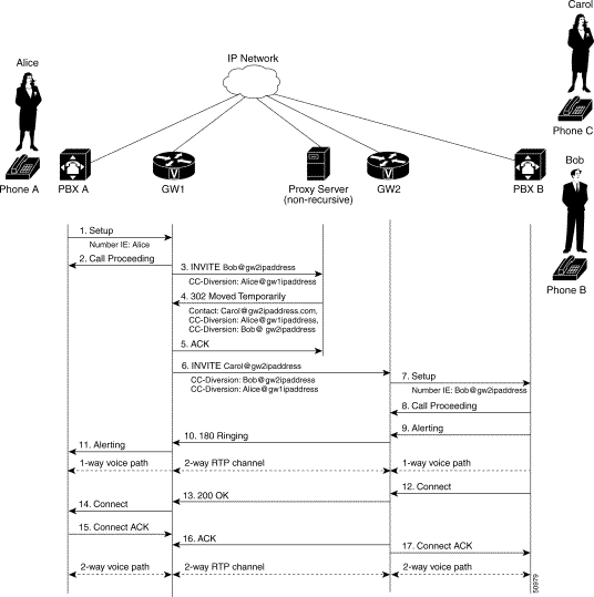
| Step | Action | Description |
|---|---|---|
1 | Setup—PBX A to SIP gateway 1 | Call Setup is initiated between PBX A and SIP gateway 1. The Call Setup includes the standard transactions that take place as Alice at phone A attempts to call Bob at phone B. |
2 | Call Proceeding—SIP gateway 1 to PBX A | SIP gateway 1 sends a Call Proceeding message to PBX A to acknowledge the Call Setup request. |
3 | INVITE—SIP gateway 1 to SIP proxy server | GW1 sends an INVITE request to the proxy server. The INVITE request is an invitation to Bob to participate in a call session. In the INVITE request:
|
4 | 302 Moved Temporarily—SIP proxy server to SIP gateway 1 | The SIP proxy server determines that Bob's calls have been configured to be redirected to Carol at phone C via GW2. The SIP proxy server sends an 302 Moved Temporarily message to GW1. In the 302 Moved Temporarily message, Carol at GW2 is added as the Contact and there are two CC-Diversion header fields included; one for Bob at GW2 (IP address or domain name) and one for Alice at GW1 (IP address or domain name). |
5 | INVITE—SIP gateway 1 to SIP gateway 2 | SIP gateway 1 sends an INVITE request to Carol at phone C via GW2. The INVITE request contains two CC-Diversion headers; one for Bob at GW2 (IP address or domain name) and one for Alice at GW1 (IP address or domain name). |
6 | Setup—SIP gateway 2 to PBX B | SIP gateway 2 receives the INVITE request from SIP gateway 1 and initiates a Call Setup with Carol via PBX B. In the Call Setup, the ISDN Redirecting Number IE is generated using the contents of the top CC-Diversion header field; in this case, Bob at GW2. |
7 | Call Proceeding—PBX B to SIP gateway 2 | PBX B sends a Call Proceeding message to SIP gateway 2 to acknowledge the Call Setup request. |
8 | Alerting—PBX B to SIP gateway 2 | PBX B locates Carol at phone C and sends an Alert message to SIP gateway 2. Carol's phone begins to ring. |
9 | 180 Ringing—SIP gateway 2 to SIP gateway 1 | SIP gateway 2 sends a 180 Ringing response to SIP gateway 1. The 180 Ringing response indicates that SIP gateway 2 has located, and is trying to alert, Carol at phone C. |
10 | Alerting—SIP gateway 1 to PBX A | SIP gateway 1 sends an Alert message to PBX A. Alice hears ringback tone. |
At this point, a one-way voice path is established between SIP gateway 1 and PBXA and between SIP gateway 2 and PBX B. A two-way RTP channel is established between SIP gateway 1 and SIP gateway 2. | ||
11 | Connect—PBX B to SIP gateway 2 | Carol answers phone. PBX B sends a Connect message to SIP gateway 2. The Connect message notifies SIP gateway 2 that the connection has been made. |
12 | 200 OK—SIP gateway 2 to SIP gateway 1 | SIP gateway 2 sends a 200 OK response to SIP gateway 1. The 200 OK response notifies SIP gateway 1 that the connection has been made. If Carol via SIP gateway 2 supports the media capability advertised in the INVITE message sent by SIP gateway 1, it advertises the intersection of its own and Alice's media capability in the 200 OK response. If Carol at SIP gateway 2 does not support the media capability advertised by Alice at SIP gateway 1, SIP gateway 2 sends back a 400 Bad Request response with a "Warning: 304 Codec negotiation failed" header field. |
13 | Connect—SIP gateway 1 to PBX A | SIP gateway 1 sends a Connect message to PBX A. The Connect message notifies PBX A that the connection has been made. |
14 | Connect ACK—PBX A to SIP gateway 1 | PBX A acknowledges SIP gateway 1's Connect message. |
15 | ACK—SIP gateway 1 to SIP gateway 2 | SIP gateway 1 sends an ACK to SIP gateway 2. The ACK confirms that the 200 OK response has been received. The call is now in progress over a two-way voice path via RTP. |
16 | Connect ACK—SIP gateway 2 to PBX B | SIP gateway 2 acknowledges PBX B's Connect message. |
At this point, a two-way voice path is established between SIP gateway 1 and PBX A and between SIP gateway 2 and PBX B. A two-way RTP channel is established between SIP gateway 1 and SIP gateway 2. | ||
Figure B-2 illustrates a successful gateway-to-gateway call setup in which a SIP 3xx Redirection response is processed after the receipt of a SIP 18x Information response.
In this scenario, the three end users are identified as Alice at phone A, Bob at phone B, and Carol at phone C. Alice at phone A is located at PBX A. PBX A is connected to SIP gateway 1 via a T1/E1. SIP gateway 1 is using a SIP redirect server. Bob at phone B and Carol at phone C are located at PBX B. PBX B is connected to SIP gateway 2 via a T1/E1. SIP gateway 1 is connected to SIP gateway 2 over an IP network.
The call flow scenario is as follows:
1. Bob at phone B has delegated his calls to Carol at phone C.
1. Alice at phone A initiates a call with Bob via SIP gateway 1that is using a SIP proxy server.
2. The proxy server returns Carol at SIP gateway 2 as a contact location for Bob.
3. Gateway 1 initiates call with Carol.
4. Carol answers the call.
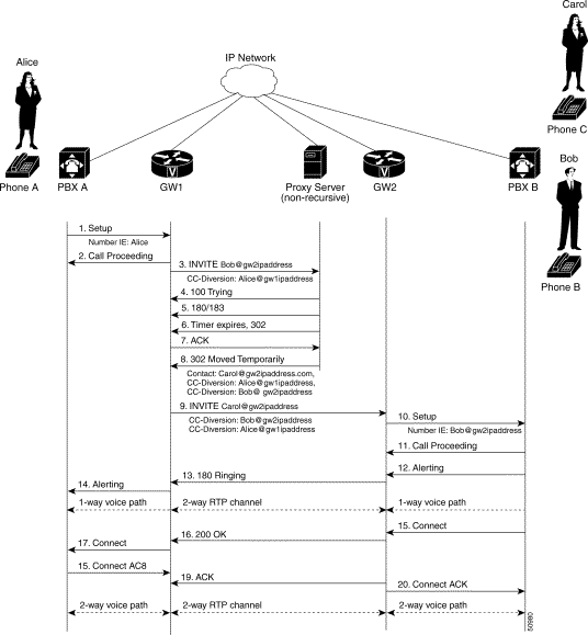
| Step | Action | Description |
|---|---|---|
1 | Setup—PBX A to SIP gateway 1 | Call Setup is initiated between PBX A and SIP gateway 1. The Call Setup includes the standard transactions that take place as Alice at phone A attempts to call Bob at phone B. |
2 | Call Proceeding—SIP gateway 1 to PBX A | SIP gateway 1 sends a Call Proceeding message to PBX A to acknowledge the Call Setup request. |
3 | INVITE—SIP gateway 1 to SIP proxy server | GW1 sends an INVITE request to the proxy server. The INVITE request is an invitation to Bob to participate in a call session. In the INVITE request:
|
4 | 183 Session Progress—SIP proxy server to SIP gateway 1 | The SIP proxy server sends a 183 Session Progress response to SIP gateway 1. |
5 | 302 Moved Temporarily—SIP proxy server to SIP gateway 1 | The SIP proxy server determines that Bob's calls have been configured to be redirected to Carol at phone C via GW2. The SIP proxy server sends an 302 Moved Temporarily message to GW1. In the 302 Moved Temporarily message, Carol at GW2 is added as the Contact and there are two CC-Diversion header fields included; one for Alice at GW1 (IP address or domain name) and Bob at GW2 (IP address or domain name). |
6 | INVITE—SIP gateway 1 to SIP gateway 2 | SIP gateway 1 sends an INVITE request to Carol at phone C via GW2. The INVITE request contains two CC-Diversion headers; one for Alice at GW1 (IP address or domain name) and Bob at GW2 (IP address or domain name). |
7 | Setup—SIP gateway 2 to PBX B | SIP gateway 2 receives the INVITE request from SIP gateway 1 and initiates a Call Setup with Carol via PBX B. In the Call Setup, the ISDN Redirecting Number IE is generated using the contents of the top CC-Diversion header field; in this case, Bob at GW2. |
8 | Call Proceeding—PBX B to SIP gateway 2 | PBX B sends a Call Proceeding message to SIP gateway 2 to acknowledge the Call Setup request. |
9 | Alerting—PBX B to SIP gateway 2 | PBX B locates Carol at phone C and sends an Alert message to SIP gateway 2. Carol's phone begins to ring. |
10 | 180 Ringing—SIP gateway 2 to SIP gateway 1 | SIP gateway 2 sends a 180 Ringing response to SIP gateway 1. The 180 Ringing response indicates that SIP gateway 2 has located, and is trying to alert, Carol at phone C. |
11 | Alerting—SIP gateway 1 to PBX A | SIP gateway 1 sends an Alert message to PBX A. Alice hears ringback tone. |
At this point, a one-way voice path is established between SIP gateway 1 and PBXA and between SIP gateway 2 and PBX B. A two-way RTP channel is established between SIP gateway 1 and SIP gateway 2. | ||
12 | Connect—PBX B to SIP gateway 2 | Carol answers phone. PBX B sends a Connect message to SIP gateway 2. The Connect message notifies SIP gateway 2 that the connection has been made. |
13 | 200 OK—SIP gateway 2 to SIP gateway 1 | SIP gateway 2 sends a 200 OK response to SIP gateway 1. The 200 OK response notifies SIP gateway 1 that the connection has been made. If Carol via SIP gateway 2 supports the media capability advertised in the INVITE message sent by SIP gateway 1, it advertises the intersection of its own and Alice's media capability in the 200 OK response. If Carol at SIP gateway 2 does not support the media capability advertised by Alice at SIP gateway 1, SIP gateway 2 sends back a 400 Bad Request response with a "Warning: 304 Codec negotiation failed" header field. |
14 | Connect—SIP gateway 1 to PBX A | SIP gateway 1 sends a Connect message to PBX A. The Connect message notifies PBX A that the connection has been made. |
15 | Connect ACK—PBX A to SIP gateway 1 | PBX A acknowledges SIP gateway 1's Connect message. |
16 | ACK—SIP gateway 1 to SIP gateway 2 | SIP gateway 1 sends an ACK to SIP gateway 2. The ACK confirms that the 200 OK response has been received. The call is now in progress over a two-way voice path via RTP. |
17 | Connect ACK—SIP gateway 2 to PBX B | SIP gateway 2 acknowledges PBX B's Connect message. |
At this point, a two-way voice path is established between SIP gateway 1 and PBX A and between SIP gateway 2 and PBX B. A two-way RTP channel is established between SIP gateway 1 and SIP gateway 2. | ||
![]()
![]()
![]()
![]()
![]()
![]()
![]()
![]()
Posted: Wed Sep 11 14:04:06 PDT 2002
All contents are Copyright © 1992--2002 Cisco Systems, Inc. All rights reserved.
Important Notices and Privacy Statement.