|
|

This chapter provides an overview of H.323 and includes the following sections:
H.323 is an ITU standard for transmitting audio, video, and data conferencing data on an IP-based internetwork. The H.323 standard provides for the following types of endpoints in the network:
Figure 1-1 shows a typical H.323 network:
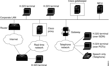
An H.323 terminal is an endpoint in the LAN that participates in real-time, two-way communications with another H.323 terminal, gateway, or multipoint control unit (MCU). A terminal must support audio communication and can also support audio with video, audio with data, or a combination of all three.
H.323 terminals must support the following standards and protocols:
Gatekeepers are optional nodes that manage other nodes in an H.323 network. Other nodes communicate with the gatekeeper using the RAS protocol. A gatekeeper is not required in an H.323 network, but it must be used if one is present.
The H.323 nodes attempt to register with a gatekeeper on startup. When an H.323 node wants to communicate with another endpoint, it requests admission to the call, using a symbolic alias for the endpoint name such as an E.164 (ITU-T recommendation for international telecommunication numbering) address or an e-mail ID. If the gatekeeper decides the call can proceed, it returns a destination IP address to the originating H.323 node. This IP address can be the actual address of the target endpoint or it can be an intermediate address. Finally, a gatekeeper and its registered endpoints exchange status information.
H.323 endpoints are grouped together in zones. Each zone has one gatekeeper that manages all the endpoints in the zone. A zone is an administrative convenience similar to a DNS domain. Gatekeeper zones are normally set up to correspond to geographic zones.
An MCU is an endpoint on the LAN that provides the capability for three or more terminals and gateways to participate in a multipoint conference. It controls and mixes video, audio, and data from terminals to create a robust video conference. An MCU can also connect two terminals in a point-to-point conference that can later develop into a multipoint conference.
 |
Note Some terminals have limited multipoint-control built into them. These terminals might not require an MCU with all the functionality mentioned previously. |
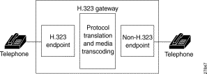
An H.323 gateway can provide an interface between H.323 and the Public Switched Telephone Network (PSTN), H.320 terminals, V.70 terminals, H.324 terminals, and other speech terminals. It provides standard interfaces to the PSTN, processes the voice and fax signals using CODECs to convert between circuit-switched and packet formats, and works with the gatekeeper through the RAS protocol to route calls through the network. Gateways provide translation between transmission formats, such as H.245 and H.242. Figure 1-2 shows a gateway between an H.323 terminal and a speech-only telephone.
Gateways provide protocol conversion between terminals running different types of protocols. Gateways communicate with gatekeepers using the RAS protocol. The gatekeeper maintains resource computing information, which it uses to select the appropriate gateway during the admission of a call. In Figure 1-3 and Figure 1-4:
Figure 1-3 illustrates the processing of a call that originates with a device in the zone (TA1) and is intended for a device outside the zone (TA2).
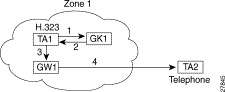
A call from TA1 to TA2 is set up as follows:
1. TA1 asks GK1 for permission to connect to TA2's E.164 address.
2. The gatekeeper looks through its local registrations and does not find any H.323 terminals registered with that E.164 address, so the gatekeeper assumes that it is a telephone outside the scope of H.323. The gatekeeper instructs TA1 to connect to the GW1 IP address.
3. TA1 connects to GW1.
4. GW1 completes the call to TA2.
Figure 1-4 illustrates the processing of a call that originates with a device outside the zone (TA2) and is intended for a device in the zone (TA1).
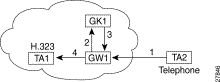
A call from TA2 to TA1 is set up as follows:
1. TA2 calls GW1 and provides the TA1 E.164 address as the final destination.
2. GW1 sends a message to GK1 asking to connect to that address.
3. GK1 gives GW1 the address of TA1.
4. GW1 completes the call with TA1.
![]()
![]()
![]()
![]()
![]()
![]()
![]()
![]()
Posted: Fri Sep 27 03:20:44 PDT 2002
All contents are Copyright © 1992--2002 Cisco Systems, Inc. All rights reserved.
Important Notices and Privacy Statement.