|
|

Table Of Contents
Overview of the IOS SLB Feature
Related Features and Technologies
Supported Standards, MIBs, and RFCs
Configuring Required and Optional IOS SLB Functions
Configuring Firewall Load Balancing
GPRS Load Balancing Configuration Task List
GGSN-IOS SLB Messaging Task List
RADIUS Load Balancing Configuration Task List
Exchange Director for CMX Configuration Task List
VPN Server Load Balancing Configuration Task List
Home Agent Director Configuration Task List
Stateless Backup Configuration Task List
Stateful Backup of Redundant Route Processors Configuration Task List
Configuring Buffers for the Fragment Database
Clearing Databases and Counters
Purging and Reassigning Connections
Disabling Automatic Server Failure Detection
Monitoring and Maintaining the IOS SLB Feature
Basic IOS SLB Network Configuration Example
Complete IOS SLB Configuration Example
IOS SLB with Firewall Load Balancing Example
IOS SLB with Server Load Balancing and Firewall Load Balancing Example
IOS SLB with Multiple Firewall Farms Example
IOS SLB with Routed Probe Example
Layer 3 Switch Configured with IOS SLB Example
IOS SLB with Static NAT Example
IOS SLB with Stateless Backup Examples
IOS SLB with Stateful Backup Example
IOS SLB with Stateful Backup of Redundant Route Processors Example
IOS SLB with Active Standby Example
IOS SLB with Redistribution of Static Routes Example
IOS SLB with WAP and UDP Load Balancing Examples
IOS SLB with Route Health Injection Examples
IOS SLB with GPRS Load Balancing Example
IOS SLB with GPRS Load Balancing and NAT Example
IOS SLB with GPRS Load Balancing, NAT, and GTP Cause Code Inspection Example
IOS SLB with VPN Server Load Balancing Example
IOS SLB with RADIUS Load Balancing for a GPRS Network Example
IOS SLB with RADIUS Load Balancing for a Simple IP CDMA2000 Network Example
IOS SLB with RADIUS Load Balancing for a Mobile IP CDMA2000 Network Example
IOS SLB with RADIUS Load Balancing for Multiple Service Gateway Farms Example
IOS SLB with Home Agent Director Example
IOS SLB with Sticky Connections Example
IOS SLB with Transparent Web Cache Load Balancing
delay (firewall farm TCP protocol)
faildetect inband (real server)
faildetect numconns (real server)
idle (firewall farm datagram protocol)
idle (firewall farm TCP protocol)
inservice (firewall farm real server)
inservice (server farm real server)
inservice (server farm virtual server)
maxconns (firewall farm datagram protocol)
maxconns (firewall farm TCP protocol)
predictor hash address (firewall farm)
probe (firewall farm real server)
purge radius framed-ip acct on-off (virtual server)
purge radius framed-ip acct stop (virtual server)
replicate casa (firewall farm)
replicate casa (virtual server)
replicate interval (firewall farm)
replicate interval (virtual server)
replicate slave (firewall farm)
replicate slave (virtual server)
sticky (firewall farm datagram protocol)
sticky (firewall farm TCP protocol)
weight (firewall farm real server)
FAQ (Frequently Asked Questions)
IOS Server Load Balancing
Feature History
12.0(7)XE
This feature was introduced with support for the following platforms:
•
Multilayer Switch Feature Card (MSFC) and Supervisor Engine 1 for Cisco Catalyst 6500 family switches
•
The following functions were provided:
•
•
•
•
•
•
12.1(1)E
The following functions were added:
12.1(2)E
The following functions were added:
•
•
•
12.1(3a)E
The following functions were added:
•
12.1(5a)E
The following functions were added:
•
•
12.1(5)T
The Cisco IOS Release 12.1(1)E feature was integrated into Cisco IOS Release 12.1(5)T, supporting Cisco 7200 series routers only.
12.2
The Cisco IOS Release 12.1(5)T feature was integrated into Cisco IOS Release 12.2.
12.1(7)E
Support for the following platform was added:
•
The following functions were added:
•
12.1(8a)E
Support for the following platform was added:
•
The following functions were added:
12.1(9)E
The following functions were added:
•
12.1(11b)E
Support for the following platforms was added:
•
The following functions were added:
•
•
12.1(12c)E
The following functions were added:
•
•
12.1(13)E
This release incorporated only minor corrections and clarifications.
12.2(14)S
This feature was integrated into Cisco IOS Release 12.2(14)S.
Support for the following platforms was removed:
•
•
•
12.1(13)E3
Support for the following platforms was added:
•
•
•
The following functions were added:
•
•
•
12.2(14)ZA2
The following function was added:
12.2(14)ZA4
The following functions were added:
•
12.2(14)ZA5
The following functions were added:
12.2(14)ZA6
This release incorporated only minor corrections and clarifications.
12.2(17d)SXB
Support for the following platforms was removed:
•
•
•
•
12.2(17d)SXB1
The following function was added:
12.2(18)SXD
Support for the following platforms was added:
•
•
The following functions were added:
•
This document describes the Cisco IOS Server Load Balancing (IOS SLB) feature in Cisco IOS Release 12.2(18)SXD. It includes the following sections:
•
•
•
•
•
•
•
•
Overview of the IOS SLB Feature
The IOS SLB feature is an IOS-based solution that provides load balancing for a variety of networked devices and services, including:
•
•
•
In addition, the IOS SLB Exchange Director enables advanced load-balancing routing capabilities for the following additional service nodes:
•
–
–
–
–
•
–
–
–
–
The Exchange Director also adds the following features:
•
•
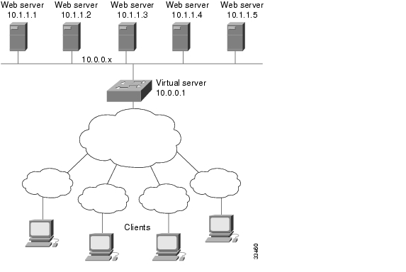
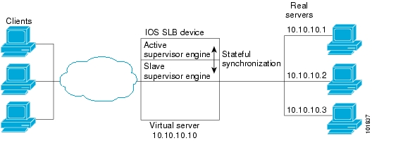
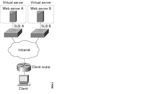
Figure 1 illustrates a logical view of a simple IOS SLB network.
Figure 1 Logical View of IOS SLB
Features
This section describes the general features provided by IOS SLB, as well as the specific features provided by the Exchange Director for Cisco Mobile Exchange (CMX).
Note
IOS SLB Features
IOS SLB provides the following features:
•
Routing Features
IOS SLB provides the following routing features:
•
•
•
•
•
•
•
Algorithms for Server Load Balancing
IOS SLB provides the following load-balancing algorithms:
You can specify one of these algorithms as the basis for choosing a real server for each new connection request that arrives at the virtual server.
Weighted Round Robin
The weighted round robin algorithm specifies that the real server used for a new connection to the virtual server is chosen from the server farm in a circular fashion. Each real server is assigned a weight, n, that represents its capacity to handle connections, as compared to the other real servers associated with the virtual server. That is, new connections are assigned to a given real server n times before the next real server in the server farm is chosen.
For example, assume a server farm comprised of real server ServerA with n = 3, ServerB with n = 1, and ServerC with n = 2. The first three connections to the virtual server are assigned to ServerA, the fourth connection to ServerB, and the fifth and sixth connections to ServerC.
Note
General packet radio service (GPRS) load balancing without GPRS Tunneling Protocol (GTP) cause code inspection enabled requires the weighted round robin algorithm. A server farm that uses weighted least connections can be bound to a virtual server providing GPRS load balancing without GTP cause code inspection enabled, but you cannot place the virtual server INSERVICE. If you try to do so, IOS SLB issues an error message.
The Home Agent Director requires the weighted round robin algorithm. A server farm that uses weighted least connections can be bound to a Home Agent Director virtual server, but you cannot place the virtual server INSERVICE. If you try to do so, IOS SLB issues an error message.Weighted Least Connections
The weighted least connections algorithm specifies that the next real server chosen from a server farm for a new connection to the virtual server is the server with the fewest active connections. Each real server is assigned a weight for this algorithm, also. When weights are assigned, the server with the fewest connections is based on the number of active connections on each server, and on the relative capacity of each server. The capacity of a given real server is calculated as the assigned weight of that server divided by the sum of the assigned weights of all of the real servers associated with that virtual server, or n1/(n1+n2+n3...).
For example, assume a server farm comprised of real server ServerA with n = 3, ServerB with n = 1, and ServerC with n = 2. ServerA would have a calculated capacity of 3/(3+1+2), or half of all active connections on the virtual server, ServerB one-sixth of all active connections, and ServerC one-third of all active connections. At any point in time, the next connection to the virtual server would be assigned to the real server whose number of active connections is farthest below its calculated capacity.
Note
GPRS load balancing without GTP cause code inspection enabled does not support the weighted least connections algorithm.
GPRS load balancing with GTP cause code inspection enabled does support the weighted least connections algorithm.
The Home Agent Director does not support the weighted least connections algorithm.Bind ID Support
The bind ID allows a single physical server to be bound to multiple virtual servers and report a different weight for each one. Thus, the single real server is represented as multiple instances of itself, each having a different bind ID. Dynamic Feedback Protocol (DFP) uses the bind ID to identify for which instance of the real server a given weight is specified. The bind ID is needed only if you are using DFP.
GPRS load balancing and the Home Agent Director do not support bind IDs.
Client-Assigned Load Balancing
Client-assigned load balancing allows you to limit access to a virtual server by specifying the list of client IP subnets that are permitted to use that virtual server. With this feature, you can assign a set of client IP subnets (such as internal subnets) connecting to a virtual IP address to one server farm or firewall farm, and assign another set of clients (such as external clients) to a different server farm or firewall farm.
GPRS load balancing and the Home Agent Director do not support client-assigned load balancing.
Content Flow Monitor Support
IOS SLB supports the Cisco Content Flow Monitor (CFM), a web-based status monitoring application within the CiscoWorks2000 product family. You can use CFM to manage Cisco server load-balancing devices. CFM runs on Windows NT and Solaris workstations, and is accessed using a web browser.
Delayed Removal of TCP Connection Context
Because of IP packet ordering anomalies, IOS SLB might "see" the termination of a TCP connection (a finish [FIN] or reset [RST]) followed by other packets for the connection. This problem usually occurs when there are multiple paths that the TCP connection packets can follow. To correctly redirect the packets that arrive after the connection is terminated, IOS SLB retains the TCP connection information, or context, for a specified length of time. The length of time the context is retained after the connection is terminated is controlled by a configurable delay timer.
Firewall Load Balancing
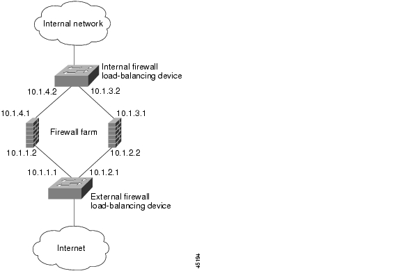
As its name implies, firewall load balancing enables IOS SLB to balance flows to firewalls. Firewall load balancing uses a load-balancing device on each side of a group of firewalls (called a firewall farm) to ensure that the traffic for each flow travels to the same firewall, ensuring that the security policy is not compromised.
You can configure more than one firewall farm in each load-balancing device.
Layer 3 firewalls, which have ip-addressable interfaces, are supported by IOS SLB firewall load balancing if they are subnet-adjacent to the firewall load-balancing device and have unique MAC addresses. The device does not modify the IP addresses in the user packet. To send the packet to the chosen firewall, the device determines which interface to use and changes the Layer 2 headers accordingly. This type of routing is the standard dispatched routing used by IOS SLB.
Layer 2 firewalls, which do not have IP addresses, are transparent to IOS SLB firewall load balancing. IOS SLB supports Layer 2 firewalls by placing them between two ip-addressable interfaces.
Whereas many Layer 3 firewalls might exist off a single Layer 3 interface on the load-balancing device (for example, a single LAN), only one Layer 2 firewall can exist off each interface.
When configuring the load-balancing device, you configure a Layer 3 firewall using its IP address, and a Layer 2 firewall using the IP address of the interface of the device on the "other side" of the firewall.
To balance flows across the firewalls in a firewall farm, IOS SLB firewall load balancing performs a route lookup on each incoming flow, examining the source and destination IP addresses (and optionally the source and destination TCP or User Datagram Protocol [UDP] port numbers). Firewall load balancing applies a hash algorithm to the results of the route lookup and selects the best firewall to handle the connection request.
Note
To maximize availability and resilience in a network with multiple firewalls, configure a separate equal-weight route to each firewall, rather than a single route to only one of the firewalls.
IOS SLB firewall load balancing provides the following capabilities:
•
•
•
•
•
•
•
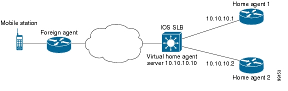
Home Agent Director
The Home Agent Director load balances Mobile IP Registration Requests (RRQs) among a set of home agents (configured as real servers in a server farm). Home agents are the anchoring points for mobile nodes. Home agents route flows for a mobile node to its current foreign agent (point of attachment).
The Home Agent Director has the following characteristics:
•
•
•
•
•
For more information about Mobile IP, home agents, and related topics, refer to the Cisco IOS IP Configuration Guide, Release 12.2.
Maximum Connections
IOS SLB allows you to configure maximum connections for server and firewall load balancing.
•
•
Multiple Firewall Farm Support
You can configure more than one firewall farm in each load-balancing device.
Network Address Translation (NAT)
Cisco IOS NAT, RFC 1631, allows unregistered "private" IP addresses to connect to the Internet by translating them into globally registered IP addresses. As part of this functionality, Cisco IOS NAT can be configured to advertise only one address for the entire network to the outside world. This configuration provides additional security and network privacy, effectively hiding the entire internal network from the world behind that address. NAT has the dual functionality of security and address conservation, and is typically implemented in remote access environments.
This section includes information about the following topics:
Session Redirection
Session redirection involves redirecting packets to real servers. IOS SLB can operate in one of two session redirection modes, dispatched mode or directed mode.
Note
Dispatched Mode
In dispatched mode, the virtual server address is known to the real servers; you must configure the virtual server IP address as a loopback address, or secondary IP address, on each of the real servers. IOS SLB redirects packets to the real servers at the media access control (MAC) layer. Since the virtual server IP address is not modified in dispatched mode, the real servers must be Layer 2-adjacent to IOS SLB, or intervening routers might not be able to route to the chosen real server.
For Catalyst 6500 family switches, dispatched mode with hardware data packet acceleration generally yields better performance than directed mode.
Refer to the "Configuring Logical Interfaces" chapter of the Cisco IOS Interface Configuration Guide, Release 12.2 for more information about configuring the loopback address.
Directed Mode
In directed mode, the virtual server can be assigned an IP address that is not known to any of the real servers. IOS SLB translates packets exchanged between a client and a real server, using NAT to translate the virtual server IP address to a real server IP address.
IOS SLB supports the following types of NAT:
•
Note
IOS SLB does not support FTP or firewall load balancing in directed mode. Therefore, FTP and firewall load balancing cannot use NAT.
IOS SLB supports only client NAT for TCP and UDP virtual servers.
IOS SLB supports only server NAT (but not server port translation) for Encapsulation Security Payload (ESP) virtual servers or Generic Routing Encapsulation (GRE) virtual servers.Server NAT
Server NAT involves replacing the virtual server IP address with the real server IP address (and vice versa). Server NAT provides the following benefits:
•
•
•
•
•
Client NAT
If you use more than one load-balancing device in your network, replacing the client IP address with an IP address associated with one of the devices results in proper routing of outbound flows to the correct device. Client NAT also requires that the ephemeral client port be modified since many clients can use the same ephemeral port. Even in cases where multiple load-balancing devices are not used, client NAT can be useful to ensure that packets from load-balanced connections are not routed around the device.
Static NAT
With static NAT, address translations exist in the NAT translation table as soon as you configure static NAT commands, and they remain in the translation table until you delete the static NAT commands.
You can use static NAT to allow some users to utilize NAT and allow other users on the same Ethernet interface to continue with their own IP addresses. This option enables you to provide a default NAT behavior for real servers, differentiating between responses from a real server, and connection requests initiated by the real server.
For example, you can use server NAT to redirect Domain Name System (DNS) inbound request packets and outbound response packets for a real server, and static NAT to process connection requests from that real server.
Note
IOS SLB supports the following static NAT options, configured using the ip slb static command:
•
•
•
•
–
–
IOS SLB uses the following logic when handling a packet from a real server:
Step 1
•
•
Step 2
•
•
Step 3
•
•
Step 4
•
•
Step 5
•
•
Step 6
•
•
Step 7
•
•
Server Port Translation
Server port translation, also known as port address translation, or PAT, is a form of server NAT that involves the translation of virtual server ports instead of virtual server IP addresses. Virtual server port translation does not require translation of the virtual server IP address, but you can use the two types of translation together.
IOS SLB supports server port translation for TCP and UDP only.
Port-Bound Servers
When you define a virtual server, you must specify the TCP or UDP port handled by that virtual server. However, if you configure NAT on the server farm, you can also configure port-bound servers. Port-bound servers allow one virtual server IP address to represent one set of real servers for one service, such as HTTP, and a different set of real servers for another service, such as Telnet.
Packets destined for a virtual server address for a port that is not specified in the virtual server definition are not redirected.
IOS SLB supports both port-bound and non-port-bound servers, but port-bound servers are recommended.
IOS SLB firewall load balancing does not support port-bound servers.
Route Health Injection
By default, a virtual server's IP address is advertised (added to the routing table) when you bring the virtual server into service (using the inservice command). If you have a preferred host route to a website's virtual IP address, you can advertise that host route, but you have no guarantee that the IP address is available. However, you can use the advertise command to configure IOS SLB to advertise the host route only when IOS SLB has verified that the IP address is available. IOS SLB withdraws the advertisement when the IP address is no longer available. This function is known as route health injection.
Sticky Connections
Sometimes, a client transaction can require multiple consecutive connections, which means new connections from the same client IP address or subnet must be assigned to the same real server. These connections are especially important in firewall load balancing, because the firewall might need to profile the multiple connections in order to detect certain attacks.
You can use the optional sticky command to enable IOS SLB to force connections from the same client to the same load-balanced server within a server farm. For firewall load balancing, the connections between the same client-server pair are assigned to the same firewall. New connections are considered to be sticky as long as the following conditions are met:
•
•
This binding of new connections to the same server or firewall is continued for a user-defined period after the last sticky connection ends.
To get the client-server address sticky behavior needed for "sandwich" firewall load balancing, you must enable sticky on both sides of the firewall farm. In this configuration, client-server sticky associations are created when an initial connection is opened between a client-server address pair. After this initial connection is established, IOS SLB maintains the sticky association in the firewall load-balancing devices on either side of the farm, and applies the sticky association to connections initiated from either the client or server IP address, by both firewall load-balancing devices.
Client subnet sticky is enabled when you specify a subnet mask on the sticky command. Subnet sticky is useful when the client IP address might change from one connection to the next. For example, before reaching IOS SLB, the client connections might pass through a set of NAT or proxy firewalls that have no sticky management of their own. Such a situation can result in failed client transactions if the servers do not have the logic to cope with it. In cases where such firewalls assign addresses from the same set of subnets, IOS SLB's sticky subnet mask can overcome the problems that they might cause.
Sticky connections also permit the coupling of services that are handled by more than one virtual server or firewall farm. This option allows connection requests for related services to use the same real server. For example, web server (HTTP) typically uses TCP port 80, and HTTPS uses port 443. If HTTP virtual servers and HTTPS virtual servers are coupled, connections for ports 80 and 443 from the same client IP address or subnet are assigned to the same real server.
Virtual servers that are in the same sticky group are sometimes called buddied virtual servers.
GPRS load balancing and the Home Agent Director do not support sticky connections.
TCP Session Reassignment
IOS SLB tracks each TCP SYN sent to a real server by a client attempting to open a new connection. If several consecutive SYNs are not answered, or if a SYN is replied to with an RST, the TCP session is reassigned to a new real server. The number of SYN attempts is controlled by a configurable reassign threshold.
IOS SLB firewall load balancing does not support TCP session reassignment.
Transparent Web Cache Load Balancing
IOS SLB can load-balance HTTP flows across a cluster of transparent web caches. To set up this function, configure the subnet IP addresses served by the transparent web caches, or some common subset of them, as virtual servers. Virtual servers used for transparent web cache load balancing do not answer pings on behalf of the subnet IP addresses, and they do not affect traceroute.
In some cases, such as when its cache does not contain needed pages, a web cache might need to initiate its own connections to the Internet. Those connections should not be load-balanced back to the same set of web caches. To address this need, IOS SLB allows you to configure client exclude statements, which exclude connections initiated by the web caches from the load-balancing scheme.
IOS SLB firewall load balancing does not support transparent web cache load balancing.
Security Features
IOS SLB provides the following security features:
•
•
Alternate IP Addresses
IOS SLB enables you to telnet to the load-balancing device using an alternate IP address. To do so, use either of the following methods:
•
•
This function is similar to that provided by the LocalDirector (LD) Alias command.
Avoiding Attacks on Server Farms and Firewall Farms
IOS SLB relies on a site's firewalls to protect the site from attacks. In general, IOS SLB is no more susceptible to direct attack than is any switch or router. However, a highly secure site can take the following steps to enhance its security:
•
•
•
•
Slow Start
In an environment that uses weighted least connections load balancing, a real server that is placed in service initially has no connections, and could therefore be assigned so many new connections that it becomes overloaded. To prevent such an overload, slow start controls the number of new connections that are directed to a real server that has just been placed in service.
GPRS load balancing and the Home Agent Director do not support slow start.
SynGuard
SynGuard limits the rate of TCP start-of-connection packets (SYNchronize sequence numbers, or SYNs) handled by a virtual server to prevent a type of network problem known as a SYN flood denial-of-service attack. A user might send a large number of SYNs to a server, which could overwhelm or crash the server, denying service to other users. SynGuard prevents such an attack from bringing down IOS SLB or a real server. SynGuard monitors the number of SYNs handled by a virtual server at specific intervals and does not allow the number to exceed a configured SYN threshold. If the threshold is reached, any new SYNs are dropped.
IOS SLB firewall load balancing and the Home Agent Director do not support SynGuard.
Server Failure Detection and Recovery Features
IOS SLB provides the following server failure detection and recovery features:
•
•
•
Automatic Server Failure Detection
IOS SLB automatically detects each failed Transmission Control Protocol (TCP) connection attempt to a real server, and increments a failure counter for that server. (The failure counter is not incremented if a failed TCP connection from the same client has already been counted.) If a server's failure counter exceeds a configurable failure threshold, the server is considered out of service and is removed from the list of active real servers.
For RADIUS load balancing, the IOS SLB performs automatic server failure detection when a RADIUS request is not answered by the real server.
If you have configured all-port virtual servers (that is, virtual servers that accept flows destined for all ports except GTP ports), flows can be passed to servers for which no application port exists. When the servers reject these flows, IOS SLB might fail the servers and remove them from load balancing. This situation can also occur in slow-to-respond AAA servers in RADIUS load-balancing environments. To prevent this situation, you can disable automatic server failure detection.
Note
If you specify the no faildetect inband command, the faildetect numconns command is ignored, if specified.Automatic Unfail
When a real server fails and is removed from the list of active servers, it is assigned no new connections for a length of time specified by a configurable retry timer. After that timer expires, the server is again eligible for new virtual server connections and IOS SLB sends the server the next qualifying connection. If the connection is successful, the failed server is placed back on the list of active real servers. If the connection is unsuccessful, the server remains out of service and the retry timer is reset. The unsuccessful connection must have experienced at least one retry, otherwise the next qualifying connection would also be sent to that failed server.
Backup Server Farms
A backup server farm is a server farm that can be used when none of the real servers defined in a primary server farm is available to accept new connections. When configuring backup server farms, keep in mind the following considerations:
•
•
•
DFP Agent Subsystem Support
IOS SLB supports the DFP Agent Subsystem feature, also called global load balancing, which enables client subsystems other than IOS SLB to act as DFP agents. With the DFP Agent Subsystem, you can use multiple DFP agents from different client subsystems at the same time.
For more information about the DFP Agent Subsystem, refer to the DFP Agent Subsystem feature document for Cisco IOS Release 12.2(18)SXD.
Dynamic Feedback Protocol for IOS SLB
With IOS SLB Dynamic Feedback Protocol (DFP) support, a DFP manager in a load-balancing environment can initiate a TCP connection with a DFP agent. Thereafter, the DFP agent collects status information from one or more real host servers, converts the information to relative weights, and reports the weights to the DFP manager. The DFP manager factors in the weights when load balancing the real servers. In addition to reporting at user-defined intervals, the DFP agent sends an early report if there is a sudden change in a real server's status.
The weights calculated by DFP override the static weights you define using the weight command in server farm configuration mode. If DFP is removed from the network, IOS SLB reverts to the static weights.
You can define IOS SLB as a DFP manager, as a DFP agent for another DFP manager, or as both at the same time. In such a configuration, IOS SLB sends periodic reports to the other DFP manager, which uses the information to choose the best server farm for each new connection request. IOS SLB then uses the same information to choose the best real server within the chosen server farm.
DFP also supports the use of multiple DFP agents from different client subsystems (such as IOS SLB and GPRS) at the same time.
See the following sections for more information:
•
DFP and GPRS Load Balancing
In GPRS load balancing, you can define IOS SLB as a DFP manager and define a DFP agent on each GGSN in the server farm. Thereafter, the DFP agent can report the weights of the GGSNs. The DFP agents calculate the weight of each GGSN based on CPU utilization, processor memory, and the maximum number of Packet Data Protocol (PDP) contexts (mobile sessions) that can be activated for each GGSN. As a first approximation, DFP calculates the weight as the number of existing PDP contexts divided by the maximum allowed PDP contexts:
(existing PDP contexts)/(maximum PDP contexts)
Maximum PDP contexts are specified using the gprs maximum-pdp-context-allowed command, which defaults to 10,000 PDP contexts. If you accept the default value, DFP might calculate a very low weight for the GGSN:
(existing PDP contexts)/10000 = Low GGSN weight
Keep this calculation in mind when specifying maximum PDP contexts using the gprs maximum-pdp-context-allowed command. For example, Cisco 7200 series routers acting as GGSNs are often configured with a maximum of 45,000 PDP contexts.
DFP and the Home Agent Director
For the Home Agent Director, you can define IOS SLB as a DFP manager and define a DFP agent on each home agent in the server farm, and the DFP agent can report the weights of the home agents. The DFP agents calculate the weight of each home agent based on CPU utilization, processor memory, and the maximum number of bindings that can be activated for each home agent:
(maximum-number-of-bindings - current-number-of-bindings)/maximum-number-of-bindings * (cpu-utilization + memory-utilization)/32 * maximum-DFP-weight = reported-weight
To set the maximum-number-of-bindings, use the ip mobile home-agent max-binding command. To set the maximum-DFP-weight sent by the home agent to IOS SLB, use the ip mobile home-agent dfp-max-weight command. For detailed information about these Mobile IP commands, refer to the Release Notes for the Cisco Home Agent 2.0 Feature in Cisco IOS Release 12.2(18)SXD.
TBD - Make sure the above release notes exist
GGSN-IOS SLB Messaging
This feature enables a GGSN to notify IOS SLB when certain conditions occur. The notifications enable IOS SLB to make intelligent decisions, which in turn improves GPRS load balancing and failure detection.
The notifications sent by the GGSN use GTP with message types from the unused space (reserved for future use) and the following information elements (IEs):
•
•
•
GGSN-IOS SLB messaging is supported in both dispatched mode and directed modes.
Probes
IOS SLB supports DNS, HTTP, ping, TCP, custom UDP, and WSP probes:
•
•
HTTP probes also enable you to monitor applications being server load-balanced. With frequent probes, the operation of each application is verified, not just connectivity to the application.
HTTP probes do not support HTTP over Secure Socket Layer (HTTPS). That is, you cannot send an HTTP probe to an SSL server.
•
•
•
–
–
–
–
–
•
You can configure more than one probe, in any combination of supported types, for each server farm, or for each firewall in a firewall farm.
You can also flag a probe as a routed probe, with the following considerations:
•
•
IOS SLB probes use the SA Agent. You might want to specify the amount of memory that the SA Agent can use, using the rtr low-memory command. If the amount of available free memory falls below the value specified in the rtr low-memory command, then the SA Agent does not allow new operations to be configured. Refer to the description of the rtr low-memory command in the Cisco IOS Configuration Fundamentals Command Reference, Release 12.2 for more details.
Probes in Server Load Balancing
Probes determine the status of each real server in a server farm. All real servers associated with all virtual servers tied to that server farm are probed.
If a real server fails for one probe, it is failed for all probes. After the real server recovers, all probes must acknowledge its recovery before it is restored to service.
Probes in Firewall Load Balancing
Probes detect firewall failures. All firewalls associated with the firewall farm are probed.
If a firewall fails for one probe, it is failed for all probes. After the firewall recovers, all probes must acknowledge its recovery before it is restored to service.
Make sure you configure the HTTP probe to expect status code 401, to eliminate password problems. Refer to the description of the expect command in the "Command Reference" section for more details.
Use the ip http server command to configure an HTTP server on the device. Refer to the description of the ip http server command in the Cisco IOS Configuration Fundamentals Command Reference, Release 12.2 for more details.
In a transparent web cache load-balancing environment, an HTTP probe uses the real IP address of the web cache, since there is no virtual IP address configured.
Protocol Support Features
IOS SLB provides the following protocol support features:
•
Protocol Support
IOS SLB supports the following protocols:
•
•
•
•
•
•
•
•
•
•
•
•
•
•
•
•
•
•
•
•
•
•
•
–
–
–
–
AAA Load Balancing
IOS SLB provides RADIUS load-balancing capabilities for RADIUS authentication, authorization, and accounting (AAA) servers.
IOS SLB provides the following RADIUS load-balancing functions:
•
•
•
•
In addition, IOS SLB can load-balance devices that proxy the RADIUS Authorization and Accounting flows in both traditional and mobile wireless networks. For more information, see the "RADIUS Load Balancing" section.
Audio and Video Load Balancing
IOS SLB can balance RealAudio and RealVideo streams via Real-Time Streaming Protocol (RTSP), for servers running RealNetworks applications.
VPN Server Load Balancing
IOS SLB can balance Virtual Private Network (VPN) flows, including the following flows:
•
•
Redundancy Features
An IOS SLB device can represent a single point of failure, and the servers can lose their connections to the backbone, if either of the following occurs:
•
•
To reduce that risk, IOS SLB supports the following redundancy enhancements, based on HSRP:
Stateless Backup
Stateless backup provides high network availability by routing IP flows from hosts on Ethernet networks without relying on the availability of a single Layer 3 switch. Stateless backup is particularly useful for hosts that do not support a router discovery protocol (such as the Intermediate System-to-Intermediate System [IS-IS] Interdomain Routing Protocol [IDRP]) and do not have the functionality to shift to a new Layer 3 switch when their selected Layer 3 switch reloads or loses power.
Stateful Backup
Stateful backup enables IOS SLB to incrementally backup its load-balancing decisions, or "keep state," between primary and backup switches. The backup switch keeps its virtual servers in a dormant state until HSRP detects failover; then the backup (now primary) switch begins advertising virtual addresses and processing flows. You can use HSRP to configure how quickly the failover is detected.
Stateful backup provides IOS SLB with a one-to-one stateful or idle backup scheme. This means that only one instance of IOS SLB is handling client or server flows at a given time, and that there is at most one backup platform for each active IOS SLB switch.
GPRS load balancing without GTP cause code inspection enabled does not support stateful backup.
The Home Agent Director does not support stateful backup.
Active Standby
Active standby enables two IOS SLBs to load-balance the same virtual IP address while at the same time acting as backups for each other. If a site has only one virtual IP address to load-balance, an access router is used to direct a subset of the flows to each IOS SLB using policy-based routing.
IOS SLB firewall load balancing does not support active standby. That is, you cannot configure two pairs of firewall load balancing devices (one pair on each side of the firewalls), with each device in each pair handling traffic and backing up its partner.
Exchange Director Features
IOS SLB supports the Exchange Director for the Cisco Mobile Exchange (CMX) for Catalyst 6500 family switches and Cisco 7600 series routers. The Exchange Director provides the following features:
•
•
•
GPRS Load Balancing
General packet radio service (GPRS) is the packet network infrastructure based on the European Telecommunications Standards Institute (ETSI) Global System for Mobile Communication (GSM) phase 2+ standards for transferring packet data from the GSM mobile user to the packet data network (PDN). The Cisco gateway GPRS support node (GGSN) interfaces with the serving GPRS support node (SGSN) using the GPRS Tunneling Protocol (GTP), which in turn uses UDP for transport. IOS SLB provides GPRS load balancing and increased reliability and availability for the GGSN.
When configuring the network shared by IOS SLB and the GGSNs, keep the following considerations in mind:
•
•
–
–
•
•
IOS SLB supports two types of GPRS load balancing:
•
•
GPRS Load Balancing without GTP Cause Code Inspection
GPRS load balancing without GTP cause code inspection enabled is recommended for Cisco GGSNs. It has the following characteristics:
•
•
•
•
GPRS Load Balancing with GTP Cause Code Inspection
GPRS load balancing with GTP cause code inspection enabled allows IOS SLB to monitor all PDP context signaling flows to and from GGSN server farms. This enables IOS SLB to monitor GTP failure cause codes, detecting system-level problems in both Cisco and non-Cisco GGSNs.
Table 1 lists the PDP create response cause codes and the corresponding actions taken by IOS SLB.
GPRS load balancing with GTP cause code inspection enabled has the following characteristics:
•
•
•
•
•
Home Agent Director
The Home Agent Director load balances Mobile IP Registration Requests (RRQs) among a set of home agents (configured as real servers in a server farm). Home agents are the anchoring points for mobile nodes. Home agents route flows for a mobile node to its current foreign agent (point of attachment).
The Home Agent Director has the following characteristics:
•
•
•
•
•
For more information about Mobile IP, home agents, and related topics, refer to the Cisco IOS IP Configuration Guide, Release 12.2.
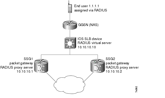
RADIUS Load Balancing
IOS SLB provides RADIUS load-balancing capabilities for RADIUS servers. In addition, IOS SLB can load-balance devices that proxy the RADIUS Authorization and Accounting flows in both traditional and mobile wireless networks, if desired. IOS SLB does this by correlating data flows to the same proxy that processed the RADIUS for that subscriber flow.
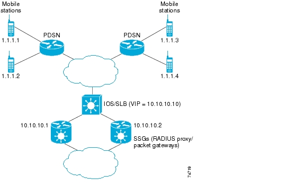
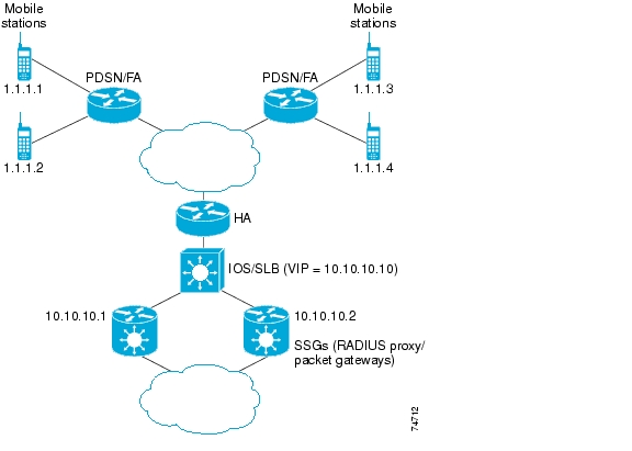
IOS SLB provides RADIUS load balancing in mobile wireless networks that use service gateways, such as the Cisco Service Selection Gateway (SSG) or the Cisco Content Services Gateway (CSG). The following mobile wireless networks are supported:
•
•
•
IOS SLB provides the following RADIUS load-balancing functions:
•
•
•
•
•
•
•
•
•
•
To perform RADIUS load balancing, IOS SLB uses the following RADIUS sticky databases:
•
Note
•
•
•
WAP Load Balancing
You can use IOS SLB to load-balance Wireless Session Protocol (WSP) sessions among a group of WAP gateways or servers on an IP bearer network. WAP runs on top of UDP on a set of well known ports, with each port indicating a different WAP mode:
•
•
•
•
IOS SLB uses WSP probes to detect failures in the WAP stack on port 9201.
Stateful Backup of Redundant Route Processors
When used with RPR+, IOS SLB supports the stateful backup of redundant route processors for CMX for Catalyst 6500 family switches and Cisco 7600 series routers. This enables you to deploy Cisco Multiprocessor WAN Application Modules (MWAMs) in the same chassis as IOS SLB, while maintaining high availability of load-balancing assignments.
Flow Persistence
Flow persistence provides intelligent return routing of load-balanced IP flows to the appropriate node, without the need for coordinated hash mechanisms on both sides of the load-balanced data path, and without using Network Address Translation (NAT) or proxies to change client or server IP addresses.
Benefits
IOS SLB shares the same software code base as Cisco IOS and has all the software features sets of Cisco IOS software. IOS SLB is recommended for customers desiring complete integration of SLB technology into traditional Cisco switches and routers.
On Cisco Catalyst 6500 family switches, IOS SLB takes advantage of hardware acceleration to forward packets at very high speed when running in dispatched mode.
IOS SLB assures continuous, high availability of content and applications with proven techniques for actively managing servers and connections in a distributed environment. By distributing user requests across a cluster of servers, IOS SLB optimizes responsiveness and system capacity, and dramatically reduces the cost of providing Internet, database, and application services for large-, medium-, and small-scale sites.
IOS SLB facilitates scalability, availability, and ease of maintenance:
•
•
•
•
Using DFP enables IOS SLB to provide weights to another load-balancing system. IOS SLB can act as a DFP manager, receiving weights from host servers, and it can act as a DFP agent, sending weights to a DFP manager. The functions are enabled independently—you can implement either one, or both, at the same time.
Administration of server applications is easier. Clients know only about virtual servers; no administration is required for real server changes.
Security of the real server is provided because its address is never announced to the external network. Users are familiar only with the virtual IP address. You can filter unwanted flows based on both IP address and TCP or UDP port numbers. Additionally, though it does not eliminate the need for a firewall, IOS SLB can help protect against some denial-of-service attacks.
In a branch office, IOS SLB allows balancing of multiple sites and disaster recovery in the event of full-site failure, and distributes the work of load balancing.
Restrictions
IOS SLB has the following restrictions:
•
•
•
•
•
•
When operating in directed mode with server NAT, real servers need not be Layer 2-adjacent to IOS SLB. This function allows for more flexible network design, since servers can be placed several Layer 3 hops away from the IOS SLB switch.
•
•
•
•
•
–
–
–
–
•
–
–
–
•
–
–
–
–
–
–
- Active standby
- Network Address Translation (NAT)
- Port-bound servers
- SynGuard
- TCP session reassignment
- Transparent web cache load balancing
•
–
–
–
–
- Bind IDs
- Client-assigned load balancing
- Slow Start
- Stateful backup (unless GTP cause code inspection is enabled)
- Sticky connections
- Weighted least connections load-balancing algorithm
•
–
–
–
–
–
–
- Bind IDs
- Client-assigned load balancing
- Slow Start
- Sticky connections
•
–
•
–
–
–
–
•
–
–
–
–
–
- The PDSN must include the User-Name attribute in all RADIUS Access-Request and Accounting-Start packets. The value of the User-Name attribute for a given subscriber must be the same in all the packets (except for Cisco PDSNs that provide MSID-based access).
- The PDSN must include the Framed-ip-address attribute and the NAS-ip-address in all RADIUS Accounting-Start and Accounting-Stop packets. The value of the Framed-ip-address attribute must equal the source IP address in subscriber data packets routed by RADIUS load balancing for SSG service.
- The PDSN must include the NAS-ip-address in all Accounting-Requests. For BSC/PCF hand-offs, the Accounting-Stop must include the 3GPP2-Session-Continue VSA with a value of 1, to prevent the destruction of RADIUS load balancing sticky database objects for the subscriber.
–
- For a given subscriber session, the PDSN and HA must send the RADIUS Access-Request and Accounting-Start packets with the User-Name attribute. The value of the User-Name attribute in all PDSN and HA RADIUS packets must be the same for the session.
- For a given subscriber session, the PDSN and HA must send RADIUS Accounting-Request packets with a Framed-ip-address attribute equal to the source IP address in subscriber data packets routed by RADIUS load balancing for SSG service. All RADIUS Accounting-Requests sent by the PDSN and HA must also include the NAS-ip-address attribute.
- The PDSN must include the 3GPP2-Correlation-Identifier attribute in all Accounting-Requests.
•
–
–
–
–
–
- Bind IDs
- Client-assigned load balancing
- Slow Start
- Stateful backup
- Sticky connections
- Weighted least connections load-balancing algorithm
•
–
•
–
–
–
•
–
The term "MSFC" refers to either an MSFC1 or an MSFC2, except when specifically differentiated.
The term "PFC" refers to either a PFC1 or a PFC2, except when specifically differentiated.
–
–
–
–
Related Features and Technologies
•
•
•
•
•
•
•
•
Related Documents
•
•
•
•
•
•
Supported Platforms
•
•
Determining Platform Support Through Cisco Feature Navigator
Cisco IOS software is packaged in feature sets that are supported on specific platforms. To get updated information regarding platform support for this feature, access Cisco Feature Navigator. Cisco Feature Navigator dynamically updates the list of supported platforms as new platform support is added for the feature.
Cisco Feature Navigator is a web-based tool that enables you to determine which Cisco IOS software images support a specific set of features and which features are supported in a specific Cisco IOS image. You can search by feature or release. Under the release section, you can compare releases side by side to display both the features unique to each software release and the features in common.
To access Cisco Feature Navigator, you must have an account on Cisco.com. If you have forgotten or lost your account information, send a blank e-mail to cco-locksmith@cisco.com. An automatic check will verify that your e-mail address is registered with Cisco.com. If the check is successful, account details with a new random password will be e-mailed to you. Qualified users can establish an account on Cisco.com by following the directions found at this URL:
Cisco Feature Navigator is updated regularly when major Cisco IOS software releases and technology releases occur. For the most current information, go to the Cisco Feature Navigator home page at the following URL:
Availability of Cisco IOS Software Images
Platform support for particular Cisco IOS software releases is dependent on the availability of the software images for those platforms. Software images for some platforms may be deferred, delayed, or changed without prior notice. For updated information about platform support and availability of software images for each Cisco IOS software release, refer to the online release notes or, if supported, Cisco Feature Navigator.
Supported Standards, MIBs, and RFCs
Standards
•
MIBs
•
•
Note
To locate and download MIBs for selected platforms, Cisco IOS releases, and feature sets, use Cisco MIB Locator found at the following URL:
http://tools.cisco.com/ITDIT/MIBS/servlet/index
If Cisco MIB Locator does not support the MIB information that you need, you can also obtain a list of supported MIBs and download MIBs from the Cisco MIBs page at the following URL:
http://www.cisco.com/public/sw-center/netmgmt/cmtk/mibs.shtml
To access Cisco MIB Locator, you must have an account on Cisco.com. If you have forgotten or lost your account information, send a blank e-mail to cco-locksmith@cisco.com. An automatic check will verify that your e-mail address is registered with Cisco.com. If the check is successful, account details with a new random password will be e-mailed to you. Qualified users can establish an account on Cisco.com by following the directions found at this URL:
RFCs
•
Configuration Tasks
Configuring IOS SLB involves identifying server farms, configuring groups of real servers in server farms, and configuring the virtual servers that represent the real servers to the clients.
For configuration examples associated with these tasks, see the "Configuration Examples" section.
For a complete description of the IOS SLB commands in this section, see the "Command Reference" section. To locate documentation of other commands that appear in this section, search online using Cisco.com.
To configure IOS SLB, perform the tasks in the following sections:
•
•
•
•
•
•
•
•
•
•
•
•
•
•
•
•
•
•
•
•
•
Configuring Required and Optional IOS SLB Functions
To configure IOS SLB functions, perform the tasks in the following sections. Required and optional tasks are indicated.
•
•
•
•
•
•
Configuring a Server Farm and Real Server
Note
To configure an IOS SLB server farm, use the following commands beginning in global configuration mode:
Note
Configuring a Virtual Server
IOS SLB supports up to 500 virtual servers.
To configure an IOS SLB virtual server, use the following commands beginning in global configuration mode:
Verifying the Virtual Server
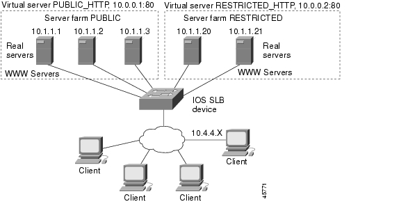
The following show ip slb vservers command verifies the configuration of the virtual servers PUBLIC_HTTP and RESTRICTED_HTTP:
Router# show ip slb vserversslb vserver prot virtual state conns-------------------------------------------------------------------PUBLIC_HTTP TCP 10.0.0.1:80 OPERATIONAL 0RESTRICTED_HTTP TCP 10.0.0.2:80 OPERATIONAL 0Router#Verifying the Server Farm
The following show ip slb reals command displays the status of server farms PUBLIC and RESTRICTED, the associated real servers, and their status:
Router# show ip slb realreal farm name weight state conns---------------------------------------------------------------------10.1.1.1 PUBLIC 8 OPERATIONAL 010.1.1.2 PUBLIC 8 OPERATIONAL 010.1.1.3 PUBLIC 8 OPERATIONAL 010.1.1.20 RESTRICTED 8 OPERATIONAL 010.1.1.21 RESTRICTED 8 OPERATIONAL 0Router#The following show ip slb serverfarm command displays the configuration and status of server farms PUBLIC and RESTRICTED:
Router# show ip slb serverfarmserver farm predictor nat reals bind id---------------------------------------------------PUBLIC ROUNDROBIN none 3 0RESTRICTED ROUNDROBIN none 2 0Router#Verifying the Clients
The following show ip slb conns command verifies the restricted client access and status:
Router# show ip slb connsvserver prot client real state nat-------------------------------------------------------------------------------RESTRICTED_HTTP TCP 10.4.4.0:80 10.1.1.20 CLOSING noneRouter#The following show ip slb conns command displays detailed information about the restricted client access status:
Router# show ip slb conns client 10.4.4.0 detailVSTEST_UDP, client = 10.4.4.0:80state = CLOSING, real = 10.1.1.20, nat = nonev_ip = 10.0.0.2:80, TCP, service = NONEclient_syns = 0, sticky = FALSE, flows attached = 0Router#Verifying IOS SLB Connectivity
To verify that the IOS SLB feature has been installed and is operating correctly, ping the real servers from the IOS SLB switch, then ping the virtual servers from the clients.
The following show ip slb stats command displays detailed information about the IOS SLB network
status:
Router# show ip slb statsPkts via normal switching: 0Pkts via special switching: 6Pkts dropped: 0Connections Created: 1Connections Established: 1Connections Destroyed: 0Connections Reassigned: 0Zombie Count: 0Connections Reused: 0Normal switching is when IOS SLB packets are handled on normal IOS switching paths (CEF, fast switching, and process level switching). Special switching is when IOS SLB packets are handled on hardware-assisted switching paths.
See the "Monitoring and Maintaining the IOS SLB Feature" section for additional commands used to verify IOS SLB networks and connections.
Configuring Firewall Load Balancing
This section describes the tasks required to configure a basic IOS SLB firewall load-balancing network.
IOS SLB firewall load balancing uses probes to detect and recover from failures. You must configure a probe on each real server in the firewall farm. Ping probes are recommended; see the "Configuring Ping Probes" section for more details. If a firewall does not allow ping probes to be forwarded, use HTTP probes instead. See the "Configuring HTTP Probes" section for more details. You can configure more than one probe, in any combination of supported types (DNS, HTTP, TCP, or ping), for each firewall in a firewall farm.
When performing server load balancing and firewall load balancing together on a Catalyst 6500 Family Switch, use the mls ip slb wildcard search rp command to reduce the probability of exceeding the capacity of the TCAM on the PFC. See the "Configuring Wildcard Searches" section for more details.
This section describes the following IOS SLB firewall load-balancing configuration tasks. Required and optional tasks are indicated.
•
•
•
Configuring the Firewall Farm
To configure an IOS SLB firewall load-balancing network, enter the following commands in order, beginning in global configuration mode:
Verifying the Firewall Farm
The following show ip slb reals command displays the status of firewall farm FIRE1, the associated real servers, and their status:
Router# show ip slb realreal farm name weight state conns--------------------------------------------------------------------10.1.1.2 FIRE1 8 OPERATIONAL 010.1.2.2 FIRE1 8 OPERATIONAL 0The following show ip slb firewallfarm command displays the configuration and status of firewall farm FIRE1:
Router# show ip slb firewallfarmfirewall farm hash state reals------------------------------------------------FIRE1 IPADDR INSERVICE 2Verifying Firewall Connectivity
To verify that IOS SLB firewall load balancing has been configured and is operating correctly:
Step 1
Step 2
Step 3
Router# show ip slb statsPkts via normal switching: 0Pkts via special switching: 0Pkts dropped: 0Connections Created: 1911871Connections Established: 1967754Connections Destroyed: 1313251Connections Reassigned: 0Zombie Count: 0Connections Reused: 59752Connection Flowcache Purges:1776582Failed Connection Allocs: 17945Failed Real Assignments: 0Normal switching is when IOS SLB packets are handled on normal IOS switching paths (CEF, fast switching, and process level switching). Special switching is when IOS SLB packets are handled on hardware-assisted switching paths.
Step 4
Router# show ip slb real detail10.1.1.3, FIRE1, state = OPERATIONAL, type = firewallconns = 299310, dummy_conns = 0, maxconns = 4294967295weight = 10, weight(admin) = 10, metric = 104, remainder = 2total conns established = 1074779, hash count = 4646server failures = 0interface FastEthernet1/0, MAC 0010.f68f.7020Step 5
Router# show ip slb connsvserver prot client real state nat-------------------------------------------------------------------------------FirewallTCP TCP 80.80.50.187:40000 10.1.1.4 ESTAB noneFirewallTCP TCP 80.80.50.187:40000 10.1.1.4 ESTAB noneFirewallTCP TCP 80.80.50.187:40000 10.1.1.4 ESTAB noneFirewallTCP TCP 80.80.50.187:40000 10.1.1.4 ESTAB noneFirewallTCP TCP 80.80.50.187:40000 10.1.1.4 ESTAB noneStep 6
Configuring Probes
IOS SLB uses probes to verify connectivity and detect failures. For a detailed description of each type of probe, see the "Probes" section.
By default, no probes are configured in IOS SLB. The following sections describe how to configure and verify probes. Required and optional tasks are indicated.
•
•
•
•
•
•
•
•
Configuring Custom UDP Probes
To configure a custom UDP probe, enter the following commands in order, beginning in global configuration mode:
Configuring DNS Probes
To configure a DNS probe, enter the following commands in order, beginning in global configuration mode:
Configuring HTTP Probes
To configure an HTTP probe, enter the following commands in order, beginning in global configuration mode:
In addition, HTTP probes require a route to the virtual server. The route is not used, but it must exist to enable the sockets code to verify that the destination can be reached, which in turn is essential for HTTP probes to function correctly. The route can be either a host route (advertised by the virtual server) or a default route (specified using the ip route 0.0.0.0 0.0.0.0 command, for example).
Configuring Ping Probes
To configure a ping probe, enter the following commands in order, beginning in global configuration mode:
Configuring TCP Probes
To configure a TCP probe, enter the following commands in order, beginning in global configuration mode:
Configuring WSP Probes
To configure a WSP probe, enter the following commands in order, beginning in global configuration mode:
Associating the Probe
After configuring a probe, you must associate it with a real server or firewall, using the probe command. See the "Configuring a Server Farm and Real Server" section and the "Configuring Firewall Load Balancing" section for more details.
Note
Verifying the Probe
To verify that a probe is configured correctly, use the show ip slb probe command:
Router# show ip slb probeServer:Port State Outages Current Cumulative----------------------------------------------------------------10.1.1.1:80 OPERATIONAL 0 never 00:00:0010.1.1.2:80 OPERATIONAL 0 never 00:00:0010.1.1.3:80 OPERATIONAL 0 never 00:00:00Router#Configuring DFP
You can define IOS SLB as a DFP manager, as a DFP agent for another DFP manager, or as both at the same time. Depending on your network configuration, you might enter the commands for configuring IOS SLB as a DFP manager and the commands for configuring IOS SLB as a DFP agent on the same device or on different devices.
To configure IOS SLB as a DFP manager, and to identify a DFP agent with which IOS SLB can initiate connections, enter the following commands in order, beginning in global configuration mode:
To configure IOS SLB as a DFP agent, refer to the DFP Agent Subsystem feature document for Cisco IOS Release 12.2(18)SXB.
GPRS Load Balancing Configuration Task List
This section lists the tasks used to configure GPRS load balancing. Detailed configuration information is contained in the referenced sections of this or other documents. Required and optional tasks are indicated.
•
When you configure the server farm and real server for GPRS load balancing, keep the following considerations in mind:
–
If GTP cause code inspection is enabled, you can specify either the weighted round robin (roundrobin) or the weighted least connections (leastconns) algorithm.
–
–
•
When you configure the virtual command, keep the following considerations in mind:
–
–
–
–
–
In GPRS load balancing without GTP cause code inspection enabled, when you configure the idle timer using the idle command, specify an idle timer greater than the longest possible interval between PDP context requests on the SGSN.
•
This step is required only if you are using dispatched mode without GTP cause code inspection enabled. Refer to the "Configuring a Loopback Interface" section in the Cisco IOS Interface Configuration Guide, Release 12.2 for more information.
•
The route can be static or dynamic, but the GGSN needs to be able to reach the SGSN. Refer to the "Configuring Network Access to the GGSN" section of the Cisco IOS Mobile Wireless Configuration Guide, Release 12.2 for more details.
•
Refer to the configuration guide for your SGSN for more details.
•
This step is applicable only if GTP cause code inspection is enabled.
Configuring a GSN Idle Timer
To configure a GPRS support node (GSN) idle timer, enter the following command in global configuration mode:
GGSN-IOS SLB Messaging Task List
This section lists the tasks used to configure GGSN-IOS SLB messaging. Detailed configuration information is contained in the referenced sections of this or other documents. Required and optional tasks are indicated.
•
When you configure GGSN-IOS SLB messaging support, configure all IOS SLB virtual servers that share the same GGSN to use the same NAT mode, either dispatched mode or directed mode, using the gprs slb mode command. The virtual servers cannot use a mix of dispatched mode and directed mode, because you can configure only one NAT mode on a given GGSN.
For more information, refer to the Cisco IOS Mobile Wireless Configuration Guide for GGSN 5.0 for Cisco IOS Release 12.3(2)XU or later.
•
When you configure the server farm and real server for GGSN-IOS SLB messaging, to prevent IOS SLB from failing the current real server when reassigning the session to a new real server, disable automatic server failure detection by specifying the no faildetect inband command.
•
(Optional) When you configure the virtual server for GGSN-IOS SLB messaging, specify the gtp notification cac command to limit the number of times IOS SLB can reassign a session to a new real server.
RADIUS Load Balancing Configuration Task List
This section lists the tasks used to configure RADIUS load balancing. Detailed configuration information is contained in the referenced sections of this or other documents. Required and optional tasks are indicated.
•
When you configure the server farm and real server for RADIUS load balancing, keep the following considerations in mind:
–
–
–
•
When you configure the virtual server for RADIUS load balancing, keep the following considerations in mind:
–
–
If you configure the access interface route framed-ip command, you must also configure the virtual command with the service radius keywords specified.
–
–
–
–
If you configure the sticky radius framed-ip command, you must also configure the virtual command with the service radius keywords specified.
–
To prevent IOS SLB from purging entries in the IOS SLB RADIUS framed-ip sticky database upon receipt of an Accounting ON or OFF message, specify the no purge radius framed-ip acct on-off virtual server configuration command.
–
To prevent IOS SLB from purging entries in the IOS SLB RADIUS framed-ip sticky database upon receipt of an Accounting-Stop message, specify the no purge radius framed-ip acct stop virtual server configuration command.
–
To enable IOS SLB to create the IOS SLB RADIUS username sticky database and direct RADIUS requests from a given subscriber to the same service gateway based on the username, specify the radius username keywords on the sticky command.
If you configure the sticky radius calling-station-id command or the sticky radius username command, you must also configure the virtual command with the service radius keywords specified, and you must configure the sticky radius framed-ip command.
You cannot configure both the sticky radius calling-station-id command and the sticky radius username command on the same virtual server.
•
•
If you are running IOS SLB in dispatched mode on a Catalyst 6500 Family Switch with Supervisor Engine 2, you can improve performance by configuring the no mls netflow command. This command increases the number of MLS entries available for hardware switching of end-user flows.
Note
For more information about configuring MLS NetFlow, refer to the Catalyst 6000 Family IOS Software Configuration Guide.
•
To verify the health of the server, configure a ping probe.
Enabling IOS SLB to Inspect Packets for RADIUS Framed-IP Sticky Routing
You can enable IOS SLB to inspect packets whose source IP addresses match a configured IP address and subnet mask. If the source IP address of an inspected packet matches an entry in the IOS SLB RADIUS framed-IP sticky database, IOS SLB uses that entry to route the packet. Otherwise, IOS routes the packet.
To enable IOS SLB to inspect packets for routing using the RADIUS framed-IP sticky database, enter the following command in global configuration mode:
Exchange Director for CMX Configuration Task List
This section contains the following information:
•
•
RADIUS Configuration for the Exchange Director
This section lists the tasks used to configure RADIUS for the Exchange Director. Detailed configuration information is contained in the referenced sections of this or other documents. Required and optional tasks are indicated.
•
When you configure the server farm and real server for RADIUS for the Exchange Director, keep the following considerations in mind:
–
–
•
When you configure the virtual server for RADIUS for the Exchange Director, keep the following considerations in mind:
–
–
If you configure the access interface route framed-ip command, you must also configure the virtual command with the service radius keywords specified.
–
–
–
–
If you configure the sticky radius framed-ip command, you must also configure the virtual command with the service radius keywords specified.
–
To enable IOS SLB to create the IOS SLB RADIUS username sticky database and direct RADIUS requests from a given subscriber to the same service gateway based on the username, specify the radius username keywords on the sticky command.
If you configure the sticky radius calling-station-id command or the sticky radius username command, you must also configure the virtual command with the service radius keywords specified, and you must configure the sticky radius framed-ip command.
You cannot configure both the sticky radius calling-station-id command and the sticky radius username command on the same virtual server.
•
•
If you are running IOS SLB in dispatched mode on a Catalyst 6500 Family Switch with Supervisor Engine 2, you can improve performance by configuring the no mls netflow command. This command increases the number of MLS entries available for hardware switching of end-user flows.
Note
For more information about configuring MLS NetFlow, refer to the Catalyst 6000 Family IOS Software Configuration Guide.
•
To verify the health of the server, configure a ping probe.
Firewall Configuration for the Exchange Director
This section lists the tasks used to configure firewalls for the Exchange Director. Detailed configuration information is contained in the referenced sections of this or other documents. Required and optional tasks are indicated.
•
To configure a firewall farm for the Exchange Director, enter the following commands in order, beginning in global configuration mode:
•
The following show ip slb reals command displays the status of firewall farm FIRE1, the associated real servers, and their status:
Router# show ip slb realreal farm name weight state conns--------------------------------------------------------------------10.1.1.2 FIRE1 8 OPERATIONAL 010.1.2.2 FIRE1 8 OPERATIONAL 0The following show ip slb firewallfarm command displays the configuration and status of firewall farm FIRE1:
Router# show ip slb firewallfarmfirewall farm hash state reals------------------------------------------------FIRE1 IPADDR INSERVICE 2•
To verify that IOS SLB firewall load balancing has been configured and is operating correctly, use the following procedure:
Step 1
Step 2
Step 3
Router# show ip slb statsPkts via normal switching: 0Pkts via special switching: 0Pkts dropped: 0Connections Created: 1911871Connections Established: 1967754Connections Destroyed: 1313251Connections Reassigned: 0Zombie Count: 0Connections Reused: 59752Connection Flowcache Purges:1776582Failed Connection Allocs: 17945Failed Real Assignments: 0Normal switching is when IOS SLB packets are handled on normal IOS switching paths (CEF, fast switching, and process level switching). Special switching is when IOS SLB packets are handled on hardware-assisted switching paths.
Step 4
Router# show ip slb real detail10.1.1.3, FIRE1, state = OPERATIONAL, type = firewallconns = 299310, dummy_conns = 0, maxconns = 4294967295weight = 10, weight(admin) = 10, metric = 104, remainder = 2total conns established = 1074779, hash count = 4646server failures = 0interface FastEthernet1/0, MAC 0010.f68f.7020Step 5
Router# show ip slb connsvserver prot client real state nat-------------------------------------------------------------------------------FirewallTCP TCP 80.80.50.187:40000 10.1.1.4 ESTAB noneFirewallTCP TCP 80.80.50.187:40000 10.1.1.4 ESTAB noneFirewallTCP TCP 80.80.50.187:40000 10.1.1.4 ESTAB noneFirewallTCP TCP 80.80.50.187:40000 10.1.1.4 ESTAB noneFirewallTCP TCP 80.80.50.187:40000 10.1.1.4 ESTAB noneStep 6
•
The Exchange Director uses probes to detect and recover from failures. You must configure a probe on each real server in the firewall farm. Ping probes are recommended; see the "Configuring Ping Probes" section for more details. If a firewall does not allow ping probes to be forwarded, use HTTP probes instead. See the "Configuring HTTP Probes" section for more details. You can configure more than one probe, in any combination of supported types (DNS, HTTP, TCP, or ping), for each firewall in a firewall farm.
•
Use the mls ip slb wildcard search rp command to reduce the probability of exceeding the capacity of the TCAM on the PFC.
VPN Server Load Balancing Configuration Task List
This section lists the tasks used to configure VPN server load balancing. Detailed configuration information is contained in the referenced sections of this or other documents. Required and optional tasks are indicated.
•
When you configure the server farm and real server for VPN server load balancing, specify the IP addresses of the real servers acting as VPN terminators, using the real command.
•
When you configure the virtual server for VPN server load balancing of IPSec flows, keep the following considerations in mind:
–
–
–
When you configure the virtual server for VPN server load balancing of PPTP flows, keep the following considerations in mind:
–
–
–
•
To verify the health of the server, configure a ping probe.
Home Agent Director Configuration Task List
This section lists the tasks used to configure the Home Agent Director. Detailed configuration information is contained in the referenced sections of this or other documents. Required and optional tasks are indicated.
•
When you configure the server farm and real server for the Home Agent Director, keep the following considerations in mind:
–
–
•
When you configure the virtual server for the Home Agent Director using the virtual command, keep the following considerations in mind:
–
–
–
–
•
Refer to the "Configuring a Loopback Interface" section in the Cisco IOS Interface Configuration Guide, Release 12.2 for more information.
•
When you configure DFP for the Home Agent Director, keep the following considerations in mind:
–
–
–
TBD - Make sure following release notes exist.
For detailed information about these Mobile IP commands, refer to the Release Notes for the Cisco Home Agent 2.0 Feature in Cisco IOS Release 12.2(18)SXD.
Configuring NAT
To configure the IOS SLB NAT client address pool for client NAT, enter the following command in global configuration mode:
You need not configure the client address pool for server NAT.
You must also specify either NAT client translation mode or NAT server address translation mode on the server farm, using the nat command. See the "Configuring a Server Farm and Real Server" section for more details. When you configure the virtual server for NAT, remember that you cannot configure client NAT for an ESP or GRE virtual server.
Configuring Static NAT
Static NAT enables you to allow some users to utilize NAT and allow other users on the same Ethernet interface to continue with their own IP addresses. This option enables you to provide a default NAT behavior for real servers, differentiating between responses from a real server, and connection requests initiated by the real server.
Note
To configure NAT for the server, enter the following commands in order, beginning in global configuration mode:
Stateless Backup Configuration Task List
This section lists the tasks used to configure stateless backup over VLANs between IOS SLB devices. Detailed configuration information is contained in the referenced sections of this or other documents. Required and optional tasks are indicated.
•
•
•
Refer to the "IP Routing Protocols" chapter of the Cisco IOS IP Configuration Guide, Release 12.2 for more details.
•
Refer to the "Virtual LANs" chapter of the Cisco IOS Switching Services Configuration Guide, Release 12.2 for more details.
•
Note
Verifying the Stateless Backup Configuration
For server load balancing, to verify that stateless backup has been configured and is operating correctly, use the following show ip slb vservers commands to display information about the IOS SLB virtual server status:
Router# show ip slb vserversslb vserver prot virtual state conns-------------------------------------------------------------------VS1 TCP 10.10.10.12:23 OPERATIONAL 2VS2 TCP 10.10.10.18:23 OPERATIONAL 2Router# show ip slb vservers detailVS1, state = OPERATIONAL, v_index = 10virtual = 10.10.10.12:23, TCP, service = NONE, advertise = TRUEserver farm = SERVERGROUP1, delay = 10, idle = 3600sticky timer = 0, sticky subnet = 255.255.255.255sticky group id = 0synguard counter = 0, synguard period = 0conns = 0, total conns = 0, syns = 0, syn drops = 0standby group = NoneVS2, state = INSERVICE, v_index = 11virtual = 10.10.10.18:23, TCP, service = NONE, advertise = TRUEserver farm = SERVERGROUP2, delay = 10, idle = 3600sticky timer = 0, sticky subnet = 255.255.255.255sticky group id = 0synguard counter = 0, synguard period = 0conns = 0, total conns = 0, syns = 0, syn drops = 0standby group = NoneFor firewall load balancing, to verify that stateless backup has been configured and is operating correctly, use the following show ip slb firewallfarm commands to display information about the IOS SLB firewall farm status:
Router# show ip slb firewallfarmfirewall farm hash state reals------------------------------------------------FIRE1 IPADDR INSERVICE 2Router# show ip slb firewallfarm detailsFIRE1, hash = IPADDRPORT, state = INSERVICE, reals = 2FirewallTCP:sticky timer = 0, sticky subnet = 255.255.255.255idle = 3600, delay = 10, syns = 1965732, syn drop = 0maxconns = 4294967295, conns = 597445, total conns = 1909512FirewallUDP:sticky timer = 0, sticky subnet = 255.255.255.255idle = 3600maxconns = 1, conns = 0, total conns = 1Real firewalls:10.1.1.3, weight = 10, OPERATIONAL, conns = 29882310.1.1.4, weight = 10, OPERATIONAL, conns = 298622Total connections = 597445Stateful Backup of Redundant Route Processors Configuration Task List
This section lists the tasks used to configure stateful backup of redundant route processors. Detailed configuration information is contained in the referenced sections of this document. Required and optional tasks are indicated.
•
Specify the ip slb replicate slave rate command in global configuration mode.
•
When you configure the virtual server for stateful backup of redundant route processors, keep the following considerations in mind:
–
–
•
When you configure the firewall farm for stateful backup of redundant route processors, keep the following considerations in mind:
–
–
Configuring Database Entries
To configure an initial allocation and a maximum value for IOS SLB database entries, enter the following command in global configuration mode:
Configuring Buffers for the Fragment Database
To configure the maximum number of buffers for the IOS SLB fragment database, enter the following command in global configuration mode:
Router(config)# ip slb maxbuffers frag buffersConfigures the maximum number of buffers for the IOS Server Load Balancing (IOS SLB) fragment database.
Clearing Databases and Counters
To clear IP IOS SLB databases and counters, enter one or more of the following commands in privileged EXEC mode:
Configuring Wildcard Searches
To specify the behavior of IOS SLB wildcard searches, enter the following command in global configuration mode:
Purging and Reassigning Connections
You can enable IOS SLB to automatically remove connections to failed real servers and firewalls from the connection database even if the idle timers have not expired. This function is useful for applications that do not rotate the source port (such as IKE), and for protocols that do not have ports to differentiate flows (such as ESP).
You can also enable IOS SLB to automatically reassign to a new real server or firewall RADIUS sticky objects that are destined for a failed real server or firewall.
To configure IOS SLB's behavior when a real server fails, enter the following commands in order, beginning in global configuration mode:
To configure IOS SLB's behavior when a firewall fails, enter the following commands in order, beginning in global configuration mode:
Disabling Automatic Server Failure Detection
If you have configured all-port virtual servers (that is, virtual servers that accept flows destined for all ports except GTP ports), flows can be passed to servers for which no application port exists. When the servers reject these flows, IOS SLB might fail the servers and remove them from load balancing. This situation can also occur in slow-to-respond AAA servers in RADIUS load-balancing environments. To prevent this situation, you can disable automatic server failure detection.
To disable automatic server failure detection, enter the following command in real server configuration mode:
Router(config-slb-real)# no faildetect inbandDisables automatic server failure detection.
Note
If you specify the no faildetect inband command, the faildetect numconns command is ignored, if specified.
Monitoring and Maintaining the IOS SLB Feature
To obtain and display runtime information about IOS SLB, use the following commands in EXEC mode:
Configuration Examples
This section provides real-world examples of IOS SLB configurations. For a complete description of the IOS SLB commands in this section, see the "Command Reference" section. To locate documentation of other commands that appear in this section, search online using Cisco.com.
This section includes the following examples:
•
•
•
•
•
•
•
•
•
•
•
•
•
•
•
•
•
•
•
•
•
•
•
•
•
•
Note
Basic IOS SLB Network Configuration Example
Figure 2 shows a sample IOS SLB network with the following components:
•
•
–
–
•
–
–
Figure 2 Example IOS SLB Network
The following sections include examples of the configuration commands used to configure and verify the IOS SLB network shown in Figure 2:
•
•
Server Farm Configuration
The following example shows the configuration for the server farm PUBLIC, associated with three real servers:
ip slb serverfarm PUBLICreal 10.1.1.1reassign 2faildetect numconns 4 numclients 2retry 20inserviceexitreal 10.1.1.2reassign 2faildetect numconns 4retry 20inserviceexitreal 10.1.1.3reassign 2faildetect numconns 4retry 20inserviceendThe following example shows the configuration for the server farm RESTRICTED, associated with two real servers:
ip slb serverfarm RESTRICTEDreal 10.1.1.20reassign 2faildetect numconns 4retry 20inserviceexitreal 10.1.1.21reassign 2faildetect numconns 4retry 20inserviceendVirtual Server Configuration
The following example shows the configuration for the virtual servers PUBLIC_HTTP and RESTRICTED_HTTP:
ip slb vserver PUBLIC_HTTPvirtual 10.0.0.1 tcp wwwserverfarm PUBLICidle 120delay 5inserviceexitip slb vserver RESTRICTED_HTTPvirtual 10.0.0.2 tcp wwwserverfarm RESTRICTEDidle 120delay 5inserviceendRestricted Client Configuration
The following example shows the configuration for the virtual server RESTRICTED_HTTP:
ip slb vserver RESTRICTED_HTTPno inserviceclient 10.4.4.0 255.255.255.0inserviceendComplete IOS SLB Configuration Example
The following example provides a complete configuration using many of the commands described in this feature document:
ip slb probe PROBE2 httprequest method POST url /probe.cgi?allheader HeaderName HeaderValue!ip slb serverfarm PUBLICnat serverreal 10.1.1.1reassign 4faildetect numconns 16retry 120inservicereal 10.1.1.2reassign 4faildetect numconns 16retry 120inserviceprobe PROBE2!ip slb serverfarm RESTRICTEDpredictor leastconnsbindid 309real 10.1.1.1weight 32maxconns 1000reassign 4faildetect numconns 16retry 120inservicereal 10.1.1.20reassign 4faildetect numconns 16retry 120inservicereal 10.1.1.21reassign 4faildetect numconns 16retry 120inservice!ip slb vserver PUBLIC_HTTPvirtual 10.0.0.1 tcp wwwserverfarm PUBLIC!ip slb vserver RESTRICTED_HTTPvirtual 10.0.0.2 tcp wwwserverfarm RESTRICTEDno advertisesticky 60 group 1idle 120delay 5client 10.4.4.0 255.255.255.0synguard 3600000inserviceIOS SLB with Firewall Load Balancing Example
Figure 3 shows a sample IOS SLB firewall load-balancing network with the following components:
•
•
•
•
Figure 3 IOS SLB with Layer 3 Firewalls in Different Subnets
When you configure IOS SLB firewall load balancing, the load-balancing devices use route lookup to recognize flows destined for the firewalls. To enable route lookup, you must configure each device with the IP address of each firewall that will route flows to that device.
In the following firewall farm configuration samples:
•
•
Internal Firewall Load-Balancing Device
The following example shows the configuration for ping probe PROBE1, HTTP probe PROBE2, and firewall farm FIRE1, associated with the two real servers for the load-balancing device on the internal (secure) side of the firewall:
!-----Ping probeip slb probe PROBE1 ping!-----IP address of other load-balancing deviceaddress 10.1.1.1faildetect 4!-----HTTP probeip slb probe PROBE2 http!-----IP address of other load-balancing deviceaddress 10.1.2.1expect status 401!-----Firewall farm FIRE1ip slb firewallfarm FIRE1!-----First firewallreal 10.1.4.1probe PROBE1!-----Enable first firewallinservice!-----Second firewallreal 10.1.3.1probe PROBE2!-----Enable second firewallinserviceExternal Firewall Load-Balancing Device
The following example shows the configuration for ping probe PROBE1, HTTP probe PROBE2, and firewall farm FIRE1, associated with the two real servers for the load-balancing device on the external (Internet) side of the firewall:
!-----Ping probeip slb probe PROBE1 ping!-----IP address of other load-balancing deviceaddress 10.1.4.2faildetect 4!-----HTTP probeip slb probe PROBE2 http!-----IP address of other load-balancing deviceaddress 10.1.3.2expect status 401!-----Firewall farm FIRE1ip slb firewallfarm FIRE1!-----First firewallreal 10.1.1.2probe PROBE1!-----Enable first firewallinservice!-----Second firewallreal 10.1.2.2probe PROBE2!-----Enable second firewallinserviceexitinserviceIOS SLB with Server Load Balancing and Firewall Load Balancing Example
Figure 4 shows a sample IOS SLB load-balancing network with server load balancing and firewall load balancing running together, and the following components:
•
•
•
•
•
•
Figure 4 IOS SLB with Server Load Balancing and Firewall Load Balancing
In the following firewall farm configuration samples:
•
•
Internal Server and Firewall Load-Balancing Device
The following example shows the configuration for ping probes ABCPROBE and XYZPROBE, firewall farm FIRE1, and server farm PUBLIC for the load-balancing device on the internal (secure) side of the firewalls:
ip slb probe ABCPROBE pingaddress 10.1.1.1ip slb probe XYZPROBE pingaddress 10.1.2.1!ip slb firewallfarm FIRE1real 10.1.4.1probe ABCPROBEinservicereal 10.1.3.1probe XYZPROBEinserviceinservice!ip slb serverfarm PUBLICnat serverreal 10.2.1.1inservicereal 10.2.1.2inservice!ip slb vserver HTTP1virtual 128.1.0.1 tcp wwwserverfarm PUBLICidle 120delay 5inservice
Note
External Firewall Load-Balancing Device
The following example shows the configuration for ping probes ABCPROBE and XYZPROBE and firewall farm FIRE1 for the load-balancing device on the external (Internet) side of the firewalls:
ip slb probe ABCPROBE pingaddress 10.1.4.2ip slb probe XYZPROBE pingaddress 10.1.3.2ip slb firewallfarm FIRE1real 10.1.1.2probe ABCPROBEinserviceprobe XYZPROBEinserviceIOS SLB with Multiple Firewall Farms Example
Figure 5 shows a sample IOS SLB load-balancing network with multiple firewall farms and the following components:
•
•
•
•
•
Figure 5 IOS SLB with Multiple Firewall Farms
In the following firewall farm configuration samples:
•
•
Internal Firewall Load-Balancing Device
The following example shows the configuration for ping probes ABCPROBE and XYZPROBE and firewall farms ABCFARM and XYZFARM for the load-balancing device on the internal (secure) side of the firewalls:
ip slb probe ABCPROBE pingaddress 10.1.2.1ip slb probe XYZPROBE pingaddress 10.1.1.1ip slb firewallfarm ABCFARMaccess source 10.1.6.0 255.255.255.0inservicereal 10.1.4.2probe ABCPROBEinservicereal 10.1.4.3probe ABCPROBEinserviceip slb firewallfarm XYZFARMaccess source 10.1.5.0 255.255.255.0inservicereal 10.1.3.2probe XYZPROBEinservicereal 10.1.3.3probe XYZPROBEinserviceExternal Firewall Load-Balancing Device
The following example shows the configuration for ping probes ABCPROBE and XYZPROBE and firewall farms ABCFARM and XYZFARM for the load-balancing device on the external (Internet) side of the firewalls:
ip slb probe ABCPROBE pingaddress 10.1.4.1ip slb probe XYZPROBE pingaddress 10.1.3.1ip slb firewallfarm ABCFARMaccess destination 10.1.6.0 255.255.255.0inservicereal 10.1.2.2probe ABCPROBEinservicereal 10.1.2.3probe ABCPROBEinserviceip slb firewallfarm XYZFARMaccess destination 10.1.5.0 255.255.255.0inservicereal 10.1.1.2probe XYZPROBEinservicereal 10.1.1.3probe XYZPROBEinserviceIOS SLB with Probes Example
Figure 6 shows a sample configuration with IOS SLB real server connections configured as part of a server farm, focusing on using ping and HTTP probes to monitor applications being server load-balanced.
Figure 6 Sample Ping and HTTP Probe Topology
:
The topology shown in Figure 6 is a heterogeneous server farm servicing a single virtual server. Following are the configuration statements for this topology, including a ping probe named PROBE1 and an HTTP probe named PROBE2:
! Configure ping probe PROBE1, change CLI to IOS SLB probe configuration modeip slb probe PROBE1 ping! Configure probe to receive responses from IP address 13.13.13.13address 13.13.13.13! Configure unacknowledged ping threshold to 16faildetect 16! Configure ping probe timer interval to send every 11 secondsinterval 11! Configure HTTP probe PROBE2ip slb probe PROBE2 http! Configure request method as POST, set URL as /probe.cgi?allrequest method post url /probe.cgi?all! Configure header HeaderNameheader HeaderName HeaderValue! Configure basic authentication username and passwordcredentials Semisweet chips! Exit to global configuration modeexit! Enter server farm configuration mode for server farm PUBLICip slb serverfarm PUBLIC! Configure NAT server and real servers on the server farmnat serverreal 10.1.1.1inservicereal 10.1.1.2inservicereal 10.1.1.3inservicereal 10.1.1.4inservicereal 10.1.1.5inservice! Configure ping probe on the server farmprobe PROBE1! Configure HTTP probe on the server farmprobe PROBE2endIOS SLB with Routed Probe Example
Figure 7 shows a typical datacenter and IOS SLB configuration. Virtual server ACME_VSERVER is configured with two real servers (10.10.10.1 and 10.10.10.2) in server farm ACME_FARM. The user wants the real servers to fail based on the health of the backend server (10.10.10.3). To accomplish this configuration without sending health checks via the real servers, the user defines BACKEND, a routed ping probe to the backend server's IP address.
Figure 7 IOS SLB with a Routed Ping Probe
Following are the IOS SLB configuration statements for the configuration shown in Figure 7:
ip slb probe BACKEND pingaddress 10.10.10.3 routedip slb serverfarm ACME_SFARMnat serverprobe BACKENDreal 10.10.10.1inservicereal 10.10.10.2inserviceip slb vserver ACME_VSERVERvirtual 10.10.10.10 tcp 80serverfarm ACME_SFARMinserviceLayer 3 Switch Configured with IOS SLB Example
Figure 8 shows a sample configuration with IOS SLB server connections configured as part of a server farm.
Figure 8 Network Configuration for IOS SLB
As shown in the following sample configuration, the example topology has three public web servers and two restricted web servers for privileged clients in subnet 10.4.4.0. The public web servers are weighted according to their capacity, with server 10.1.1.2 having the lowest capacity and having a connection limit imposed on it. The restricted web servers are configured as members of the same sticky group, so that HTTP connections and Secure Socket Layer (SSL) connections from the same client use the same real server.
The network configuration to provide the previously described IOS SLB functionality follows:
ip slb probe PROBE2 httprequest method POST url /probe.cgi?allheader HeaderName HeaderValueheader Authorization Basic U2VtaXN3ZWV0OmNoaXBz!ip slb serverfarm PUBLICnat serverpredictor leastconns! First real serverreal 10.1.1.1reassign 4faildetect numconns 16retry 120inservice! Second real serverreal 10.1.1.2reassign 4faildetect numconns 16retry 120inservice! Third real serverreal 10.1.1.3reassign 4faildetect numconns 16retry 120inservice! Probeprobe PROBE2! Restricted web server farmip slb serverfarm RESTRICTEDpredictor leastconns! First real serverreal 10.1.1.20reassign 2faildetect numconns 4retry 20inservice! Second real serverreal 10.1.1.21reassign 2faildetect numconns 4retry 20inservice!! Unrestricted web virtual serverip slb vserver PUBLIC_HTTPvirtual 10.0.0.1 tcp wwwserverfarm PUBLICidle 120delay 5inservice!! Restricted HTTP virtual serverip slb vserver RESTRICTED_HTTPvirtual 10.0.0.1 tcp wwwserverfarm RESTRICTEDclient 10.4.4.0 255.255.255.0sticky 60 group 1idle 120delay 5inservice!! Restricted SSL virtual serverip slb vserver RESTRICTED_SSLvirtual 10.0.0.1 tcp httpsserverfarm RESTRICTEDclient 10.4.4.0 255.255.255.0sticky 60 group 1idle 120delay 5inservice!interface GigabitEthernet1/1switchportswitchport access vlan 3switchport mode accessno ip address!interface FastEthernet2/1switchportswitchport access vlan 2switchport mode accessno ip address!interface FastEthernet2/2switchportswitchport access vlan 2switchport mode accessno ip address!interface FastEthernet2/3switchportswitchport access vlan 2switchport mode accessno ip address!interface Vlan2ip address 10.1.1.100 255.255.255.0!interface Vlan3ip address 40.40.40.1 255.255.255.0IOS SLB with NAT Example
Figure 9 shows a sample configuration with IOS SLB real server connections configured as part of a server farm, focusing on the configuration of the NAT server and address pool of clients.
Figure 9 Sample IOS SLB NAT Topology
The topology in Figure 9 has four web servers, configured as follows:
•
•
Server 1 and Server 2 are load-balanced using Switch A, which is performing server address translation.
Server 3 and Server 4 are load-balanced using Switch B and Switch C. These two switches are performing both server and client address translation since there are multiple paths between the clients and the servers. These switches also must perform server port translation for HTTP packets to and from Server 4.
Switch A Configuration Statements
ip slb serverfarm FARM1! Translate server addressesnat server! Server 1 port 80real 10.1.1.1reassign 2faildetect numconns 4 numclients 2retry 20inservice! Server 2 port 80real 10.2.1.1reassign 2faildetect numconns 4retry 20inservice!ip slb vserver HTTP1! Handle HTTP (port 80) requestsvirtual 128.1.0.1 tcp wwwserverfarm FARM1idle 120delay 5inserviceSwitch B Configuration Statements
ip slb natpool web-clients 128.3.0.1 128.3.0.254! NAT address pool for clientsip slb serverfarm FARM2! Translate server addressesnat server! Translate client addressesnat client web-clients! Server 3 port 80real 10.3.1.1reassign 2faildetect numconns 4retry 20inservice! Server 4 port 8080real 10.4.1.1 port 8080reassign 2faildetect numconns 4retry 20inservice! Server 4 port 8081real 10.4.1.1 port 8081reassign 2faildetect numconns 4retry 20inservice! Server 4 port 8082real 10.4.1.1 port 8082reassign 2faildetect numconns 4retry 20inservice!ip slb vserver HTTP2! Handle HTTP (port 80) requestsvirtual 128.2.0.1 tcp wwwserverfarm FARM2idle 120delay 5inserviceSwitch C Configuration Statements
ip slb natpool web-clients 128.5.0.1 128.5.0.254! NAT address pool for clientsip slb serverfarm FARM2! Translate server addressesnat server! Translate client addressesnat client web-clients! Server 3 port 80real 10.3.1.1reassign 2faildetect numconns 4retry 20inservice! Server 4 port 8080real 10.4.1.1 port 8080reassign 2faildetect numconns 4retry 20inservice! Server 4 port 8081real 10.4.1.1 port 8081reassign 2faildetect numconns 4retry 20inservice! Server 4 port 8082real 10.4.1.1 port 8082reassign 2faildetect numconns 4retry 20inservice!ip slb vserver HTTP2! Handle HTTP (port 80) requestsvirtual 128.4.0.1 tcp wwwserverfarm FARM2idle 120delay 5inserviceIOS SLB with Static NAT Example
The following example shows configuration statements for the following items:
•
•
•
•
ip slb probe PROBE4 dnslookup 13.13.13.13!ip slb serverfarm DNSnat serverprobe PROBE4real 10.1.1.3inservice!ip slb vserver DNSvirtual 10.11.11.11 UDP 0 service per-packetserverfarm DNS!ip slb static nat 10.11.11.11 per-packetreal 10.1.1.3IOS SLB with Stateless Backup Examples
There are several different ways in which you can configure IOS SLB stateless backup. The differences between the configurations depend on the networking capabilities of your load balancing devices, and on the capabilities of the distribution devices that direct client traffic to those load balancing devices.
•
•
•
•
•
This section contains the following examples, illustrating several different IOS SLB stateless backup configurations:
•
•
•
•
Note
Dynamic Routing and Trunking Example
Figure 10 shows a sample IOS SLB stateless backup configuration with the following characteristics:
•
•
•
•
•
•
Figure 10 Stateless Backup with Layer 3 and Trunking
SLB 1 Configuration Statements
ip slb serverfarm SF1real 10.10.1.3reassign 2faildetect numconns 4 numclients 2retry 20inservicereal 10.10.1.4reassign 2faildetect numconns 4retry 20inserviceip slb vserver VS1virtual 10.10.14.1 tcp wwwserverfarm SF1idle 120delay 5inservice standby SERVER!interface Ethernet1switchportswitchport vlan 1interface Ethernet2ip address 10.10.2.1 255.255.255.0interface vlan 1ip address 10.10.1.1 255.255.255.0standby ip 10.10.1.100standby priority 10 preempt delay sync 20standby name SERVERstandby track Ethernet2standby timers 1 3router eigrp 666redistribute staticnetwork 10.0.0.0SLB 2 Configuration Statements
ip slb serverfarm SF1real 10.10.1.3reassign 2faildetect numconns 4retry 20inservicereal 10.10.1.4reassign 2faildetect numconns 4retry 20inserviceip slb vserver VS1virtual 10.10.14.1 tcp wwwserverfarm SF1idle 120delay 5inservice standby SERVER!interface GigabitEthernet1no ip addressswitchportswitchport trunk encapsulation islinterface Ethernet1switchportswitchport vlan 1interface Ethernet2ip address 10.10.3.1 255.255.255.0interface vlan 1ip address 10.10.1.2 255.255.255.0standby ip 10.10.1.100standby priority 5 preempt delay sync 20standby name SERVERstandby track Ethernet2standby timers 1 3router eigrp 666redistribute staticnetwork 10.0.0.0Dynamic Routing and No Trunking Example
Figure 11 shows a sample IOS SLB stateless backup configuration with the following characteristics:
•
•
•
•
•
Figure 11 Stateless Backup with Layer 3 and No Trunking
SLB 1 Configuration Statements
ip slb serverfarm SF1real 10.10.1.3reassign 2faildetect numconns 4retry 20inservicereal 10.10.1.4reassign 2faildetect numconns 4retry 20inserviceip slb vserver VS1virtual 10.10.14.1 tcp wwwserverfarm SF1idle 120delay 5inservice standby SERVER!interface Ethernet1ip address 10.10.1.1 255.255.255.0standby ip 10.10.1.100standby priority 10 preempt delay sync 20standby name SERVERstandby track Ethernet2standby timers 1 3interface Ethernet2ip address 10.10.2.1 255.255.255.0router eigrp 666redistribute staticnetwork 10.0.0.0SLB 2 Configuration Statements
ip slb serverfarm SF1real 10.10.1.3reassign 2faildetect numconns 4retry 20inservicereal 10.10.1.4reassign 2faildetect numconns 4retry 20inserviceip slb vserver VS1virtual 10.10.14.1 tcp wwwserverfarm SF1idle 120delay 5inservice standby SERVER!interface Ethernet1ip address 10.10.1.2 255.255.255.0standby ip 10.10.1.100standby priority 5 preempt delay sync 20standby name SERVERstandby track Ethernet2standby timers 1 3interface Ethernet2ip address 10.10.3.1 255.255.255.0router eigrp 666redistribute staticnetwork 10.0.0.0Static Routing and Trunking Example
Figure 12 shows a sample IOS SLB stateless backup configuration with the following characteristics:
•
•
•
•
•
•
Figure 12 Stateless Backup with Layer 2 and Trunking
SLB 1 Configuration Statements
ip slb serverfarm SF1real 10.10.1.3reassign 2faildetect numconns 4retry 20inservicereal 10.10.1.4reassign 2faildetect numconns 4retry 20inserviceip slb vserver VS1virtual 10.10.14.1 tcp wwwserverfarm SF1idle 120delay 5inservice standby SERVER!interface Ethernet1switchportswitchport vlan 1interface Ethernet2ip address 10.10.2.1 255.255.255.0standby ip 10.10.2.100standby priority 10 preempt delay sync 20standby track vlan1standby timers 1 3interface vlan 1ip address 10.10.1.1 255.255.255.0standby ip 10.10.1.100standby priority 10 preempt delay sync 20standby name SERVERstandby track Ethernet2standby timers 1 3SLB 2 Configuration Statements
ip slb serverfarm SF1real 10.10.1.3reassign 2faildetect numconns 4retry 20inservicereal 10.10.1.4reassign 2faildetect numconns 4retry 20inserviceip slb vserver VS1virtual 10.10.14.1 tcp wwwserverfarm SF1idle 120delay 5inservice standby SERVER!interface GigabitEthernet1no ip addressswitchportswitchport trunk encapsulation islinterface Ethernet1switchportswitchport vlan 1interface Ethernet2ip address 10.10.2.2 255.255.255.0standby ip 10.10.2.100standby priority 5 preempt delay sync 20standby track vlan 1standby timers 1 3interface vlan 1ip address 10.10.1.2 255.255.255.0standby ip 10.10.1.100standby priority 5 preempt delay sync 20standby name SERVERstandby track Ethernet2standby timers 1 3Distribution Device Configuration Statements
interface Ethernet1switchportswitchport distribution vlan 2interface Ethernet2switchportswitchport distribution vlan 2interface vlan2ip address 10.10.2.3 255.255.255.0no shutip route 10.10.14.1 255.255.255.255 10.10.2.100Static Routing and No Trunking Example
Figure 13 shows a sample IOS SLB stateless backup configuration with the following characteristics:
•
•
•
•
•
Figure 13 Stateless Backup with Layer 2 and No Trunking
SLB 1 Configuration Statements
ip slb serverfarm SF1real 10.10.1.3reassign 2faildetect numconns 4retry 20inservicereal 10.10.1.4reassign 2faildetect numconns 4retry 20inserviceip slb vserver VS1virtual 10.10.14.1 tcp wwwserverfarm SF1idle 120delay 5inservice standby SERVER!interface Ethernet1ip address 10.10.1.1 255.255.255.0standby ip 10.10.1.100standby priority 10 preempt delay sync 20standby name SERVERstandby track Ethernet2standby timers 1 3interface Ethernet2ip address 10.10.2.1 255.255.255.0standby ip 10.10.2.100standby priority 10 preempt delay sync 20standby track Ethernet1standby timers 1 3SLB 2 Configuration Statements
ip slb serverfarm SF1real 10.10.1.3reassign 2faildetect numconns 4retry 20inservicereal 10.10.1.4reassign 2faildetect numconns 4retry 20inserviceip slb vserver VS1virtual 10.10.14.1 tcp wwwserverfarm SF1idle 120delay 5inservice standby SERVER!interface Ethernet1ip address 10.10.1.2 255.255.255.0standby ip 10.10.1.100standby priority 5 preempt delay sync 20standby name SERVERstandby track Ethernet2standby timers 1 3interface Ethernet2ip address 10.10.2.2 255.255.255.0standby ip 10.10.2.100standby priority 5 preempt delay sync 20standby track Ethernet1standby timers 1 3Distribution Device Configuration Statements
interface Ethernet1switchportswitchport distribution vlan 2interface Ethernet2switchportswitchport distribution vlan 2interface vlan2ip address 10.10.2.3 255.255.255.0no shutip route 10.10.14.1 255.255.255.255 10.10.2.100IOS SLB with Stateful Backup Example
This sample configuration focuses on the IOS SLB real server connections configured as part of a server farm, with real and virtual servers over Fast Ethernet interfaces configured with stateful backup standby connections.
Figure 14 is an example of a stateful backup configuration, using HSRP on both the client and server sides to handle failover. The real servers route outbound flows to 10.10.3.100, which is the HSRP address on the server side interfaces. The client (or access router), routes to the virtual IP address (10.10.10.12) through 10.10.2.100, HSRP address on the client side.
Notice the loopback interfaces configured on both devices for the exchange of these messages. Each IOS SLB should also be given duplicate routes to the other switch loopback address. This configuration allows replication messages to flow despite an interface failure.
Note
Figure 14 IOS SLB Stateful Environment
Switch SLB1 Configuration Statements
ip slb serverfarm SF1nat serverreal 10.10.3.1inservicereal 10.10.3.2inservicereal 10.10.3.3inservice!ip slb vserver VS1virtual 10.10.10.12 tcp telnetserverfarm SF1replicate casa 10.10.99.132 10.10.99.99 1024 password PASSinservice standby virt!interface loopback 1ip address 10.10.99.132 255.255.255.255!interface FastEthernet1ip address 10.10.3.132 255.255.255.0no ip redirectsno ip mroute-cachestandby priority 5 preemptstandby name outstandby ip 10.10.3.100standby track FastEthernet2standby timers 1 3interface FastEthernet2ip address 10.10.2.132 255.255.255.0no ip redirectsstandby priority 5standby name virtstandby ip 10.10.2.100standby timers 1 3Switch SLB2 Configuration Statements
ip slb serverfarm SF1nat serverreal 10.10.3.1inservicereal 10.10.3.2inservicereal 10.10.3.3inservice!ip slb vserver VS1virtual 10.10.10.12 tcp telnetserverfarm SF1replicate casa 10.10.99.99 10.10.99.132 1024 password PASSinservice standby virt!interface loopback 1ip address 10.10.99.99 255.255.255.255!interface FastEthernet2ip address 10.10.2.99 255.255.255.0no ip redirectsno ip route-cacheno ip mroute-cachestandby priority 10 preempt delay sync 20standby name virtstandby ip 10.10.2.100standby track FastEthernet3standby timers 1 3!interface FastEthernet3ip address 10.10.3.99 255.255.255.0no ip redirectsno ip route-cacheno ip mroute-cachestandby priority 10 preempt delay 20standby name outstandby ip 10.10.3.100standby track FastEthernet2standby timers 1 3IOS SLB with Stateful Backup of Redundant Route Processors Example
In Figure 15, the IOS SLB device includes two Supervisor engines configured for stateful backup. If the active Supervisor engine fails, the backup Supervisor engine takes over via RPR+ with IOS SLB synchronization information already populated. IOS SLB replicates state information for virtual server ACME_VSERVER (10.10.10.10) from the active Supervisor engine to the backup every 20 seconds. The real servers (10.10.10.1, 10.10.10.2, and 10.10.10.3) are configured in server farm ACME_SFARM.
Figure 15 IOS SLB with Redundant Route Processors
Following are the IOS SLB configuration statements for the configuration shown in Figure 15:
ip slb replicate slave rate 300ip slb serverfarm ACME_SFARMnat serverreal 10.10.10.1inservicereal 10.10.10.2inservicereal 10.10.10.3inserviceip slb vserver ACME_VSERVERvirtual 10.10.10.10 tcp 80replicate interval 20replicate slaveserverfarm ACME_SFARMinserviceIOS SLB with Active Standby Example
Figure 16 shows an IOS SLB network configured for active standby, with two IOS SLB devices load-balancing the same virtual IP address while backing up each other. If either device fails, the other takes over its load via normal HSRP failover and IOS SLB stateless redundancy.
Figure 16 IOS SLB Active Standby
The sample network configuration in Figure 16 has the following characteristics:
•
•
•
•
•
•
SLB 1 Configuration Statements
ip slb serverfarm EVENnat serverreal 10.10.3.2reassign 2faildetect numconns 4 numclients 2retry 20inservicereal 10.10.3.3reassign 2faildetect numconns 4retry 20inservice!ip slb serverfarm ODDnat serverreal 10.10.3.2reassign 2faildetect numconns 4retry 20inservicereal 10.10.3.3reassign 2faildetect numconns 4retry 20inservice!-----Same EVEN virtual server as in SLB 2ip slb vserver EVENvirtual 10.10.10.12 tcp wwwserverfarm EVENclient 0.0.0.0 0.0.0.1idle 120delay 5!-----See standby name in Ethernet 3/3 belowinservice standby STANDBY_EVEN!-----Same ODD virtual server as in SLB 2ip slb vserver ODDvirtual 10.10.10.12 tcp wwwserverfarm ODDclient 0.0.0.1 0.0.0.1idle 120delay 5!-----See standby name in Ethernet 3/2 belowinservice standby STANDBY_ODD!interface Ethernet3/2ip address 10.10.5.132 255.255.255.0standby priority 20 preempt delay sync 20!-----See standby name in SLB 2, Ethernet 3/5standby name STANDBY_ODDstandby ip 10.10.5.100standby track Ethernet3/3standby timers 1 3!interface Ethernet3/3ip address 10.10.2.132 255.255.255.0standby priority 10!-----See standby name in SLB 2, Ethernet 3/1standby name STANDBY_EVENstandby ip 10.10.2.100standby track Ethernet3/2standby timers 1 3SLB 2 Configuration Statements
ip slb serverfarm EVENnat serverreal 10.10.3.4reassign 2faildetect numconns 4retry 20inservicereal 10.10.3.5reassign 2faildetect numconns 4retry 20inservice!ip slb serverfarm ODDnat serverreal 10.10.3.4reassign 2faildetect numconns 4retry 20inservicereal 10.10.3.5reassign 2faildetect numconns 4retry 20inservice!-----Same EVEN virtual server as in SLB 1ip slb vserver EVENvirtual 10.10.10.12 tcp wwwserverfarm EVENclient 0.0.0.0 0.0.0.1idle 120delay 5!-----See standby name in Ethernet 3/1 belowinservice standby STANDBY_EVEN!-----Same ODD virtual server as in SLB 1ip slb vserver ODDvirtual 10.10.10.12 tcp wwwserverfarm ODDclient 0.0.0.1 0.0.0.1idle 120delay 5!-----See standby name in Ethernet 3/5 belowinservice standby STANDBY_ODD!interface Ethernet3/1ip address 10.10.2.128 255.255.255.0standby priority 20 preempt delay sync 20!-----See standby name in SLB 1, Ethernet 3/3standby name STANDBY_EVENstandby ip 10.10.2.100standby track Ethernet3/5standby timers 1 3!interface Ethernet3/5ip address 10.10.5.128 255.255.255.0standby priority 10 preempt delay sync 20!-----See standby name in SLB 1, Ethernet 3/2standby name STANDBY_ODDstandby ip 10.10.5.100standby track Ethernet3/1standby timers 1 3Access Router Configuration Statements
interface Ethernet0/0ip address 10.10.5.183 255.255.255.0no ip directed-broadcastno ip route-cacheno ip mroute-cache!interface Ethernet0/1ip address 10.10.2.183 255.255.255.0no ip directed-broadcastno ip route-cacheno ip mroute-cache!interface Ethernet0/2ip address 10.10.6.183 255.255.255.0no ip directed-broadcastno ip route-cacheno ip mroute-cacheip policy route-map virts!access-list 100 permit ip 0.0.0.1 255.255.255.254 host 10.10.10.12access-list 101 permit ip 0.0.0.0 255.255.255.254 host 10.10.10.12route-map virts permit 10match ip address 100set ip next-hop 10.10.5.100!route-map virts permit 15match ip address 101set ip next-hop 10.10.2.100IOS SLB with Redistribution of Static Routes Example
Figure 17 shows an IOS SLB network configured to distribute static routes to a virtual server's IP address. The route to the address is added to the routing table as static if you advertise the address when you bring the virtual server into service (using the inservice command). See the description of the advertise command in the "Command Reference" section for more details about advertising virtual server IP addresses.
Because the routing configuration varies from protocol to protocol, sample configurations for several different routing protocols are given.
Figure 17 IOS SLB Redistribution of Static Routes
Routing Information Protocol (RIP)
Following is the RIP static route redistribution configuration for the IOS SLB switch shown in Figure 17:
router ripredistribute staticnetwork 10.0.0.0network 8.0.0.0Following is the RIP static route redistribution configuration for the access router that is listening for routing updates shown in Figure 17:
router ripnetwork 10.0.0.0network 8.0.0.0Open Shortest Path First (OSPF)
Following is the OSPF static route redistribution configuration for the IOS SLB switch shown in Figure 17:
router ospf 1redistribute static subnetsnetwork 10.10.6.217 0.0.0.0 area 0network 8.8.8.0 0.0.0.255 area 0Following is the OSPF static route redistribution configuration for the access router that is listening for routing updates shown in Figure 17:
router ospf 1network 10.10.6.2 0.0.0.0 area 0network 8.8.8.0 0.0.0.255 area 0Interior Gateway Routing Protocol (IGRP)
Following is the IGRP static route redistribution configuration for the IOS SLB switch shown in Figure 17:
router igrp 1redistribute connectedredistribute staticnetwork 8.0.0.0network 10.0.0.0Following is the IGRP static route redistribution configuration for the access router that is listening for routing updates shown in Figure 17:
router igrp 1network 8.0.0.0network 10.0.0.0Enhanced Interior Gateway Routing Protocol (Enhanced IGRP)
Following is the Enhanced IGRP static route redistribution configuration for the IOS SLB switch shown in Figure 17:
router eigrp 666redistribute staticnetwork 10.0.0.0network 8.0.0.0Following is the Enhanced IGRP static route redistribution configuration for the access router that is listening for routing updates shown in Figure 17:
router eigrp 666network 10.0.0.0network 8.0.0.0IOS SLB with WAP and UDP Load Balancing Examples
Figure 18 shows an IOS SLB network configured to balance WAP flows. In this example:
•
•
•
Figure 18 IOS SLB with WAP Load Balancing
There are two ways to configure IOS SLB load balancing for WAP:
•
•
WAP Load Balancing Example
The following example shows the configuration for the IOS SLB device shown in Figure 18, which balances WAP flows on UDP port 9201 (WSP/WTP/UDP):
ip slb probe PROBE3 wspurl http://localhost/test.txt!ip slb serverfarm WAPFARMnat serverreal 10.10.2.1inservicereal 10.10.2.2inservicereal 10.10.2.3inserviceprobe PROBE3!ip slb vserver VSERVERvirtual 10.10.1.1 udp 9201serverfarm WAPFARMidle 3000inserviceUDP Load Balancing Example
The following example shows the configuration for the IOS SLB device shown in Figure 18, which balances WAP flows on UDP port 9203 (WSP/WTP/WTLS/UDP):
ip slb probe PROBE1 ping!ip slb serverfarm WAPFARMnat serverreal 10.10.2.1inservicereal 10.10.2.2inservicereal 10.10.2.3inserviceprobe PROBE1!ip slb vserver VSERVERvirtual 10.10.1.1 udp 9203serverfarm WAPFARMidle 3000inserviceIOS SLB with Route Health Injection Examples
This section contains the following examples, illustrating several different IOS SLB route health injection configurations:
•
•
•
Example with Two Distributed Sites with One Web Server Each
Figure 19 shows an IOS SLB network configured with route health injection with the following characteristics:
•
•
•
Figure 19 Two Distributed Sites with One Web Server Each
When both web servers in Figure 19 are operational, the client router receives the host route from both IOS SLB devices.
If Web Server A fails, the virtual server for the virtual IP address on SLB A enters FAILED state and stops advertising the host route for the virtual IP address. The client router then begins using the route to SLB B.
When Web Server A is again available, the virtual server again advertises the host route for the virtual IP address, and the client router begins using SLB A.
Example with Two Distributed Sites with Two Web Servers Each
Figure 20 shows an IOS SLB network configured with route health injection with the following characteristics:
•
•
•
Figure 20 Two Distributed Sites with Two Web Servers Each
When all web servers in Figure 20 are operational, the client router receives the host route from both IOS SLB devices.
If one web server in either server farm fails, the route continues to be advertised by the given IOS SLB device.
If both Web Server A1 and Web Server A2 fail, the virtual server for the virtual IP address on SLB A enters FAILED state and stops advertising the host route for the virtual IP address. The client router then begins using the route to SLB B.
When either Web Server A1 or Web Server A2 is again available, the virtual server again advertises the host route for the virtual IP address, and the client router begins using SLB A.
Example with Two Distributed Sites with One Web Server and a Backup IOS SLB Switch Each
Figure 21 shows an IOS SLB network configured with route health injection with the following characteristics:
•
•
•
•
Figure 21 Two Distributed Sites with One Web Server and a Backup IOS SLB Switch Each
When both web servers in Figure 21 are operational, the client router receives the host route from both SLB A Primary and SLB B Primary.
If SLB A Primary fails, SLB A Backup begins advertising the host route to the virtual IP address. If SLB A Backup also fails, the virtual server for the virtual IP address on SLB A Primary and SLB A Backup enters FAILED state and stops advertising the host route for the virtual IP address. The client router then begins using the route to SLB B Primary (or to SLB B Backup, if SLB B Primary is not available).
When either SLB A Primary or SLB A Backup is again available, the virtual server again advertises the host route for the virtual IP address, and the client router begins using SLB A Primary or SLB A Backup.
IOS SLB with GPRS Load Balancing Example
Figure 22 shows a typical GPRS load-balancing configuration without GTP cause code inspection enabled. In this configuration:
•
•
•
•
•
Figure 22 IOS SLB with GPRS Load Balancing
Following are the configuration statements for the configuration shown in Figure 22:
•
•
•
•
For more detailed GGSN configuration examples, refer to the Cisco IOS Mobile Wireless Configuration Guide, Release 12.2.
IOS SLB Configuration Statements
hostname GTP_SLB!ip domain-name gprs.com!ip slb serverfarm GPRSreal 192.168.1.1weight 1faildetect numconns 1 numclients 1inservice!real 192.168.2.2weight 1faildetect numconns 1 numclients 1inservice!real 192.168.3.3weight 1faildetect numconns 1 numclients 1inservice!ip slb vserver FOR_GPRSvirtual 10.10.10.10 udp 3386 service gtpserverfarm GPRSinservice!ip slb dfp password Password1 0agent 10.1.1.201 1111 30 0 10agent 10.1.1.202 1111 30 0 10agent 10.1.1.203 1111 30 0 10!interface FastEthernet1/0description TO SERVERFARM GPRSip address 10.1.1.100 255.255.255.0no ip redirectsduplex half!interface FastEthernet3/0description TO SGSNip address 10.2.1.100 255.255.255.0no ip mroute-cacheduplex half!ip route 10.111.111.111 255.255.255.255 FastEthernet1/0ip route 192.168.1.1 255.255.255.255 10.1.1.201ip route 192.168.2.2 255.255.255.255 10.1.1.202ip route 192.168.3.3 255.255.255.255 10.1.1.203GGSN1 Configuration Statements
service gprs ggsn!hostname GGSN1!ip dfp agent gprsport 1111password Password1 0inservice!ip domain-name gprs.com!interface loopback 1description LOOPBACK SAME AS IOS SLB VSERVER ADDRESSip address 10.10.10.10 255.255.255.255no ip route-cacheno ip mroute-cache!interface FastEthernet1/0description TO SLBip address 10.1.1.201 255.255.255.0ip directed-broadcastno ip mroute-cacheduplex half!interface Virtual-Template1description GTP VIRTUAL TEMPLATEip address 192.168.1.1 255.255.255.0encapsulation gtpgprs access-point-list gprs1!ip route 10.111.111.111 255.255.255.255 FastEthernet1/0!gprs access-point-list gprs1access-point 1access-point-name gprs.company.comaccess-mode non-transparentip-address-pool dhcp-proxy-clientdhcp-server 10.100.0.5 10.100.0.6dhcp-gateway-address 10.27.3.1exit!gprs maximum-pdp-context-allowed 45000gprs qos map canonical-qosgprs gtp path-echo-interval 0gprs dfp max-weight 32gprs slb cef 10.10.10.10GGSN2 Configuration Statements
service gprs ggsn!hostname GGSN2!ip dfp agent gprsport 1111password Password1 0inservice!ip domain-name gprs.com!interface loopback 1description LOOPBACK SAME AS IOS SLB VSERVER ADDRESSip address 10.10.10.10 255.255.255.255no ip route-cacheno ip mroute-cache!interface FastEthernet1/0description TO SLBip address 10.1.1.202 255.255.255.0ip directed-broadcastno ip mroute-cacheduplex half!interface Virtual-Template1description GTP VIRTUAL TEMPLATEip address 192.168.2.2 255.255.255.0encapsulation gtpgprs access-point-list gprs1!ip route 10.111.111.111 255.255.255.255 FastEthernet1/0!gprs access-point-list gprs1access-point 1access-point-name gprs.company.comaccess-mode non-transparentip-address-pool dhcp-proxy-clientdhcp-server 10.100.0.5 10.100.0.6dhcp-gateway-address 10.27.3.1exit!gprs maximum-pdp-context-allowed 45000gprs qos map canonical-qosgprs gtp path-echo-interval 0gprs dfp max-weight 32gprs slb cef 10.10.10.10GGSN3 Configuration Statements
service gprs ggsn!hostname GGSN3!ip dfp agent gprsport 1111password Password1 0inservice!ip domain-name gprs.com!interface loopback 1description LOOPBACK SAME AS IOS SLB VSERVER ADDRESSip address 10.10.10.10 255.255.255.255no ip route-cacheno ip mroute-cache!interface FastEthernet1/0description TO SLBip address 10.1.1.203 255.255.255.0ip directed-broadcastno ip mroute-cacheduplex half!interface Virtual-Template1description GTP VIRTUAL TEMPLATEip address 192.168.3.3 255.255.255.0encapsulation gtpgprs access-point-list gprs1!ip route 10.111.111.111 255.255.255.255 FastEthernet1/0!gprs access-point-list gprs1access-point 1access-point-name gprs.company.comaccess-mode non-transparentip-address-pool dhcp-proxy-clientdhcp-server 10.100.0.5 10.100.0.6dhcp-gateway-address 10.27.3.1exit!gprs maximum-pdp-context-allowed 45000gprs qos map canonical-qosgprs gtp path-echo-interval 0gprs dfp max-weight 32gprs slb cef 10.10.10.10IOS SLB with GPRS Load Balancing and NAT Example
The following example uses the same basic configuration as in the "IOS SLB with GPRS Load Balancing Example" section, including the network shown in Figure 22, but with the addition of NAT:
•
•
•
•
For more detailed GGSN configuration examples, refer to the Cisco IOS Mobile Wireless Configuration Guide, Release 12.2.
IOS SLB Configuration Statements
hostname GTP_SLB!ip domain-name gprs.com!ip slb serverfarm GPRSnat serverreal 192.168.1.1weight 1faildetect numconns 1 numclients 1inservice!real 192.168.2.2weight 1faildetect numconns 1 numclients 1inservice!real 192.168.3.3weight 1faildetect numconns 1 numclients 1inservice!ip slb vserver FOR_GPRSvirtual 10.10.10.10 udp 3386 service gtpserverfarm GPRSinservice!ip slb dfp password Password1 0agent 10.1.1.201 1111 30 0 10agent 10.1.1.202 1111 30 0 10agent 10.1.1.203 1111 30 0 10!interface FastEthernet1/0description TO SERVERFARM GPRSip address 10.1.1.100 255.255.255.0no ip redirectsduplex half!interface FastEthernet3/0description TO SGSNip address 10.2.1.100 255.255.255.0no ip mroute-cacheduplex half!ip route 10.111.111.111 255.255.255.255 FastEthernet1/0ip route 192.168.1.1 255.255.255.255 10.1.1.201ip route 192.168.2.2 255.255.255.255 10.1.1.202ip route 192.168.3.3 255.255.255.255 10.1.1.203GGSN1 Configuration Statements
service gprs ggsn!hostname GGSN1!ip dfp agent gprsport 1111password Password1 0inservice!ip domain-name gprs.com!interface FastEthernet1/0description TO SLBip address 10.1.1.201 255.255.255.0ip directed-broadcastno ip mroute-cacheduplex half!interface Virtual-Template1description GTP VIRTUAL TEMPLATEip address 192.168.1.1 255.255.255.0encapsulation gtpgprs access-point-list gprs1!ip route 10.111.111.111 255.255.255.255 FastEthernet1/0!gprs access-point-list gprs1access-point 1access-point-name gprs.company.comaccess-mode non-transparentip-address-pool dhcp-proxy-clientdhcp-server 10.100.0.5 10.100.0.6dhcp-gateway-address 10.27.3.1exit!gprs maximum-pdp-context-allowed 45000gprs qos map canonical-qosgprs gtp path-echo-interval 0gprs dfp max-weight 32GGSN2 Configuration Statements
service gprs ggsn!hostname GGSN2!ip dfp agent gprsport 1111password Password1 0inservice!ip domain-name gprs.com!interface FastEthernet1/0description TO SLBip address 10.1.1.202 255.255.255.0ip directed-broadcastno ip mroute-cacheduplex halfinterface Virtual-Template1description GTP VIRTUAL TEMPLATEip address 192.168.2.2 255.255.255.0encapsulation gtpgprs access-point-list gprs1!ip route 10.111.111.111 255.255.255.255 FastEthernet1/0!gprs access-point-list gprs1access-point 1access-point-name gprs.company.comaccess-mode non-transparentip-address-pool dhcp-proxy-clientdhcp-server 10.100.0.5 10.100.0.6dhcp-gateway-address 10.27.3.1exit!gprs maximum-pdp-context-allowed 45000gprs qos map canonical-qosgprs gtp path-echo-interval 0gprs dfp max-weight 32GGSN3 Configuration Statements
service gprs ggsn!hostname GGSN3!ip dfp agent gprsport 1111password Password1 0inservice!ip domain-name gprs.com!interface FastEthernet1/0description TO SLBip address 10.1.1.203 255.255.255.0ip directed-broadcastno ip mroute-cacheduplex half!interface Virtual-Template1description GTP VIRTUAL TEMPLATEip address 192.168.3.3 255.255.255.0encapsulation gtpgprs access-point-list gprs1!ip route 10.111.111.111 255.255.255.255 FastEthernet1/0!gprs access-point-list gprs1access-point 1access-point-name gprs.company.comaccess-mode non-transparentip-address-pool dhcp-proxy-clientdhcp-server 10.100.0.5 10.100.0.6dhcp-gateway-address 10.27.3.1exit!gprs maximum-pdp-context-allowed 45000gprs qos map canonical-qosgprs gtp path-echo-interval 0gprs dfp max-weight 32IOS SLB with GPRS Load Balancing, NAT, and GTP Cause Code Inspection Example
The following example uses the same basic configuration as in the "IOS SLB with GPRS Load Balancing and NAT Example" section, including the network shown in Figure 22, but with the GTP cause code inspection enabled. In this configuration:
•
•
•
Following are the configuration statements for the configuration shown in Figure 22, with the addition of NAT and GTP cause code inspection support:
•
•
•
•
For more detailed GGSN configuration examples, refer to the Cisco IOS Mobile Wireless Configuration Guide, Release 12.2.
IOS SLB Configuration Statements
hostname GTP_SLB!ip domain-name gprs.com!ip slb timers gtp gsn 20!ip slb serverfarm GPRSnat serverreal 192.168.1.1weight 1faildetect numconns 1 numclients 1inservice!real 192.168.2.2weight 1faildetect numconns 1 numclients 1inservice!real 192.168.3.3weight 1faildetect numconns 1 numclients 1inservice!ip slb vserver FOR_GPRSvirtual 10.10.10.10 udp 0 service gtp-inspectidle gtp request 15client gtp carrier-code mcc 222 mnc 22serverfarm GPRSinservice!ip slb dfp password Password1 0agent 10.1.1.201 1111 30 0 10agent 10.1.1.202 1111 30 0 10agent 10.1.1.203 1111 30 0 10!interface FastEthernet1/0description TO SERVERFARM GPRSip address 10.1.1.100 255.255.255.0no ip redirectsduplex half!interface FastEthernet3/0description TO SGSNip address 10.2.1.100 255.255.255.0no ip mroute-cacheduplex half!ip route 10.111.111.111 255.255.255.255 FastEthernet1/0ip route 192.168.1.1 255.255.255.255 10.1.1.201ip route 192.168.2.2 255.255.255.255 10.1.1.202ip route 192.168.3.3 255.255.255.255 10.1.1.203IOS SLB with VPN Server Load Balancing Example
Figure 23 shows a typical VPN server load-balancing configuration. In this configuration:
•
•
•
•
Figure 23 IOS SLB with VPN Server Load Balancing
Following are the IOS SLB configuration statements for the configuration shown in Figure 23:
ip slb serverfarm VPNnat serverreal 20.20.20.10inservicereal 20.20.20.20inservicefailaction purge!ip slb vserver ESPvirtual 10.10.1.1 ESPserverfarm VPNsticky 3600 group 69inservice!ip slb vserver UDPvirtual 10.10.1.1 UDP isakmpserverfarm VPNsticky 3600 group 69inserviceIOS SLB with RADIUS Load Balancing for a GPRS Network Example
Figure 24 shows a typical IOS SLB RADIUS load-balancing configuration for a GPRS network. In this configuration:
•
•
•
•
Figure 24 IOS SLB with RADIUS Load Balancing for a GPRS Network
Following are the IOS SLB configuration statements for the configuration shown in Figure 24:
ip slb route 1.1.0.0 255.255.0.0 framed-ip!ip slb serverfarm SSGFARMnat serverreal 10.10.10.1inservicereal 10.10.10.2inservice!ip slb vserver RADIUS_ACCTvirtual 10.10.10.10 udp 1812 service radiusserverfarm SSGFARMidle radius request 20idle radius framed-ip 7200sticky radius framed-ip group 1inservice!ip slb vserver RADIUS_AUTHvirtual 10.10.10.10 udp 1813 service radiusserverfarm SSGFARMidle radius request 20idle radius framed-ip 7200sticky radius framed-ip group 1inserviceIOS SLB with RADIUS Load Balancing for a Simple IP CDMA2000 Network Example
Figure 25 shows a typical IOS SLB RADIUS load-balancing configuration for a CDMA2000 network with simple IP service. In this configuration:
•
•
•
•
Figure 25 IOS SLB with RADIUS Load Balancing for a Simple IP CDMA2000 Network
Following are the IOS SLB configuration statements for the configuration shown in Figure 25:
ip slb route 1.1.0.0 255.255.0.0 framed-ip!ip slb serverfarm SSGFARMnat serverreal 10.10.10.1inservicereal 10.10.10.2inservice!ip slb vserver RADIUS_SIPvirtual 10.10.10.10 udp 0 service radiusserverfarm SSGFARMidle radius framed-ip 3600sticky radius usernamesticky radius framed-ipinserviceIOS SLB with RADIUS Load Balancing for a Mobile IP CDMA2000 Network Example
Figure 26 shows a typical IOS SLB RADIUS load-balancing configuration for a CDMA2000 network with Mobile IP service. In this configuration:
•
•
•
•
Figure 26 IOS SLB with RADIUS Load Balancing for a Mobile IP CDMA2000 Network
Following are the IOS SLB configuration statements for the configuration shown in Figure 26:
ip slb route 1.1.0.0 255.255.0.0 framed-ip!ip slb serverfarm SSGFARMnat serverreal 10.10.10.1inservicereal 10.10.10.2inservice!ip slb vserver RADIUS_SIPvirtual 10.10.10.10 udp 0 service radiusserverfarm SSGFARMidle radius framed-ip 3600sticky radius usernamesticky radius framed-ipinserviceIOS SLB with RADIUS Load Balancing for Multiple Service Gateway Farms Example
The following sample configuration enables IOS SLB to balance packet flows for a set of subscribers among multiple service gateway server farms (in this sample, a server farm of SSGs and a server farm of CSGs):
ip slb route 1.1.0.0 255.255.0.0 framed-ip!ip slb serverfarm SSGFARMnat serverreal 10.10.10.1inservicereal 10.10.10.2inservice!ip slb serverfarm CSGFARMnat serverreal 20.20.20.1inservicereal 20.20.20.2inservice!ip slb vserver SSG_AUTHvirtual 10.10.10.10 udp 1812 service radiusserverfarm SSGFARMidle radius request 20idle radius framed-ip 7200sticky radius framed-ip group 1access Vlan20 route framed-ipinservice!ip slb vserver SSG_ACCTvirtual 10.10.10.10 udp 1813 service radiusserverfarm SSGFARMidle radius request 20idle radius framed-ip 7200sticky radius framed-ip group 1access Vlan20 route framed-ipinservice!ip slb vserver CSG_ACCTvirtual 20.20.20.20 udp 1813 service radiusserverfarm CSGFARMidle radius request 25idle radius framed-ip 0sticky radius framed-ipaccess Vlan30 route framed-ipinserviceIOS SLB with Home Agent Director Example
The following sample configuration enables IOS SLB to balance Mobile IP RRQs among multiple home agents.
Figure 27 IOS SLB with Home Agent Director
Following are the IOS SLB configuration statements for the configuration shown in Figure 27:
ip slb serverfarm HA_FARMnat serverreal 10.10.10.1inservicereal 10.10.10.2inserviceip slb vserver VIRTUAL_HAvirtual 10.10.10.10 udp 434 service ipmobileserverfarm HA_FARMinserviceIOS SLB with Sticky Connections Example
The following sample configuration assigns all HTTP connections from a subnet to the same real server in server farm PUBLIC:
ip slb vserver httpserverfarm PUBLICsticky 30 group 1 netmask 255.255.255.248virtual 20.20.20.20 tcp 80inserviceThe following sample configuration adds HTTPS connections to the above configuration, using the same sticky information but with a different virtual server:
ip slb vserver httpsserverfarm PUBLICsticky 30 group 1 netmask 255.255.255.248virtual 20.20.20.20 tcp 443inserviceNow, all HTTP and HTTPS connections from the subnet are assigned to the same real server. For example, if a user connects to HTTP, then a second user connects to HTTPS, both connections are assigned to the same real server.
IOS SLB with Transparent Web Cache Load Balancing
In the following sample configuration, virtual server WEBCACHE examines all web flows passing through the load-balancing device and dispatches them to server farm WEBCACHE-FARM. The client exclude statement ignores flows originating from subnet 80.80.7.0, enabling the real servers 80.80.7.188 and 80.80.7.189 to communicate with the Internet as needed.
ip slb serverfarm WEBCACHE-FARMreal 80.80.7.188inservicereal 80.80.7.189inserviceip slb vserver WEBCACHEvirtual 0.0.0.0 0.0.0.0 tcp wwwserverfarm WEBCACHE-FARMclient 80.80.7.0 255.255.255.0 excludeinserviceCommand Reference
This section documents only new and modified commands.
•
•
•
•
•
•
•
•
•
•
•
•
•
•
•
•
•
•
•
•
•
•
•
•
•
•
•
•
•
•
•
•
access (firewall farm)
To route specific flows to a firewall farm, use the access command in firewall farm configuration mode. To restore the default settings, use the no form of this command.
access [source source-ip netmask] [destination destination-ip netmask]
no access [source source-ip netmask] [destination destination-ip netmask]
Syntax Description
Defaults
The default source IP address is 0.0.0.0 (routes flows from all sources to this firewall farm).
The default source IP network mask is 0.0.0.0 (routes flows from all source subnets to this firewall farm).
The default destination IP address is 0.0.0.0 (routes flows from all destinations to this firewall farm).
The default destination IP network mask is 0.0.0.0 (routes flows from all destination subnets to this firewall farm).Command Modes
Firewall farm configuration
Command History
12.1(7)E
This command was introduced.
12.2(14)S
This command was integrated into Cisco IOS Release 12.2(14)S.
Usage Guidelines
You can specify more than one source or destination for each firewall farm. To do so, configure multiple access statements, making sure the network masks do not overlap each other.
Examples
The following example routes flows with a destination IP address of 10.1.6.0 to firewall farm FIRE1:
Router(config)# ip slb firewallfarm FIRE1Router(config-slb-fw)# access destination 10.1.6.0 255.255.255.0Related Commands
access (virtual server)
To enable framed-IP routing to inspect the ingress interface, use the access command in virtual server configuration mode. To disable framed-IP routing, use the no form of this command.
access interface route framed-ip
no access interface route framed-ip
Syntax Description
Defaults
Framed-IP routing cannot inspect the ingress interface.
Command Modes
Virtual server configuration
Command History
12.1(12c)E
This command was introduced.
12.2(14)S
This command was integrated into Cisco IOS Release 12.2(14)S.
Usage Guidelines
You can specify more than one source or destination for each firewall farm. To do so, configure multiple access statements, making sure the network masks do not overlap each other.
This command enables framed-IP routing to inspect the ingress interface when routing subscriber traffic. All framed-IP sticky database entries created as a result of RADIUS requests to this virtual server will include the interface in the entry. In addition to matching the source IP address of the traffic with the framed-IP address, the ingress interface must also match this interface when this command is configured.
You can use this command to allow subscriber data packets to be routed to multiple service gateway service farms.
Examples
The following example enables framed-IP routing to inspect ingress interface Vlan20:
Router(config)# ip slb vserver SSG_AUTHRouter(config-slb-vserver)# access Vlan20 route framed-ipRelated Commands
Displays information about the virtual servers defined to IOS Server Load Balancing (IOS SLB).
address (custom UDP probe)
To configure an IP address to which to send custom User Datagram Protocol (UDP) probes, use the address command in custom UDP probe configuration mode. To restore the default settings, use the no form of this command.
address [ip-address] [routed]
no address [ip-address] [routed]
Syntax Description
Defaults
If the custom UDP probe is associated with a firewall farm, you must specify an IP address.
If the custom UDP probe is associated with a server farm, and you do not specify an IP address, the address is inherited from the server farm real servers.Command Modes
Custom UDP probe configuration
Command History
Examples
The following example configures a custom UDP probe named PROBE6, enters custom UDP probe configuration mode, and configures the probe to receive responses from IP address 13.13.13.13:
Router(config)# ip slb probe PROBE6 custom udpRouter(config-slb-probe)# address 13.13.13.13Related Commands
address (DNS probe)
To configure an IP address to which to send Domain Name System (DNS) probes, use the address command in DNS probe configuration mode. To restore the default settings, use the no form of this command.
address [ip-address [routed]]
no address [ip-address [routed]]
Syntax Description
Defaults
If the DNS probe is associated with a firewall farm, you must specify an IP address.
If the DNS probe is associated with a server farm, and you do not specify an IP address, the address is inherited from the server farm real servers.Command Modes
DNS probe configuration
Command History
12.1(11b)E
This command was introduced.
12.1(12c)E
The routed keyword was added.
12.2(14)S
This command was integrated into Cisco IOS Release 12.2(14)S.
Examples
The following example configures a DNS probe named PROBE4, enters DNS probe configuration mode, and configures the probe to receive responses from IP address 13.13.13.13:
Router(config)# ip slb probe PROBE4 dnsRouter(config-slb-probe)# address 13.13.13.13Related Commands
Configures a Domain Name System (DNS) probe name and enters DNS probe configuration mode.
Displays information about an IOS Server Load Balancing (IOS SLB) probe.
address (HTTP probe)
To configure an IP address to which to send HTTP probes, use the address command in HTTP probe configuration mode. To restore the default settings, use the no form of this command.
address [ip-address [routed]]
no address [ip-address [routed]]
Syntax Description
Defaults
If the HTTP probe is associated with a firewall farm, you must specify an IP address.
If the HTTP probe is associated with a server farm, and you do not specify an IP address, the address is inherited from the server farm real servers.Command Modes
HTTP probe configuration
Command History
12.1(3a)E
This command was introduced.
12.1(12c)E
The routed keyword was added.
12.2(14)S
This command was integrated into Cisco IOS Release 12.2(14)S.
Examples
The following example configures an HTTP probe named PROBE2, enters HTTP probe configuration mode, and configures the probe to receive responses from IP address 13.13.13.13:
Router(config)# ip slb probe PROBE2 httpRouter(config-slb-probe)# address 13.13.13.13Related Commands
Configures an HTTP probe name and enters HTTP probe configuration mode.
Displays information about an IOS Server Load Balancing (IOS SLB) probe.
address (ping probe)
To configure an IP address to which to send ping probes, use the address command in ping probe configuration mode. To restore the default settings, use the no form of this command.
address [ip-address [routed]]
no address [ip-address [routed]]
Syntax Description
Defaults
If the ping probe is associated with a firewall farm, you must specify an IP address.
If the ping probe is associated with a server farm, and you do not specify an IP address, the address is inherited from the server farm real servers.Command Modes
Ping probe configuration
Command History
12.1(3a)E
This command was introduced.
12.1(12c)E
The routed keyword was added.
12.2(14)S
This command was integrated into Cisco IOS Release 12.2(14)S.
Examples
The following example configures a ping probe named PROBE1, enters ping probe configuration mode, and configures the probe to receive responses from IP address 13.13.13.13:
Router(config)# ip slb probe PROBE1 pingRouter(config-slb-probe)# address 13.13.13.13Related Commands
Configures a ping probe name and enters ping probe configuration mode.
Displays information about an IOS Server Load Balancing (IOS SLB) probe.
address (TCP probe)
To configure an IP address to which to send TCP probes, use the address command in TCP probe configuration mode. To restore the default settings, use the no form of this command.
address [ip-address [routed]]
no address [ip-address [routed]]
Syntax Description
Defaults
If the TCP probe is associated with a firewall farm, you must specify an IP address
If the TCP probe is associated with a server farm, and you do not specify an IP address, the address is inherited from the server farm real servers.Command Modes
TCP probe configuration
Command History
12.1(11b)E
This command was introduced.
12.1(12c)E
The routed keyword was added.
12.2(14)S
This command was integrated into Cisco IOS Release 12.2(14)S.
Examples
The following example configures a TCP probe named PROBE5, enters TCP probe configuration mode, and configures the probe to receive responses from IP address 13.13.13.13:
Router(config)# ip slb probe PROBE5 tcpRouter(config-slb-probe)# address 13.13.13.13Related Commands
Configures a TCP probe name and enters TCP probe configuration mode.
Displays information about an IOS Server Load Balancing (IOS SLB) probe.
address (WSP probe)
To configure an IP address to which to send Wireless Session Protocol (WSP) probes, use the address command in WSP probe configuration mode. To restore the default settings, use the no form of this command.
address [ip-address [routed]]
no address [ip-address [routed]]
Syntax Description
Defaults
If the WSP probe is associated with a firewall farm, you must specify an IP address.
If the WSP probe is associated with a server farm, and you do not specify an IP address, the address is inherited from the server farm real servers.
In dispatched mode, the ip-address argument value is the same as the virtual server IP address. In directed Network Address Translation (NAT) mode, an IP address is unnecessary.Command Modes
WSP probe configuration
Command History
12.1(5a)E
This command was introduced.
12.1(12c)E
The routed keyword was added.
12.2(14)S
This command was integrated into Cisco IOS Release 12.2(14)S.
Examples
The following example configures a WSP probe named PROBE3, enters WSP probe configuration mode, and configures the probe to receive responses from IP address 13.13.13.13:
Router(config)# ip slb probe PROBE3 wspRouter(config-slb-probe)# address 13.13.13.13Related Commands
Configures a Wireless Session Protocol (WSP) probe name and enters WSP probe configuration mode.
Displays information about an IOS Server Load Balancing (IOS SLB) probe.
advertise
To control the installation of a static route to the Null0 interface for a virtual server address, use the advertise command in virtual server configuration mode. To prevent the installation of a static route for the virtual server IP address, use the no form of this command.
advertise [active]
no advertise [active]
Syntax Description
Defaults
The virtual server IP address is advertised. That is, a static route to the Null0 interface is installed for the virtual server IP addresses and it is added to the routing table.
If you do not specify the active keyword, the host route is advertised regardless of whether the virtual IP address is available.Command Modes
Virtual server configuration
Command History
Usage Guidelines
Advertisement of a static route using the routing protocol requires that you configure redistribution of static routes for the routing protocol.
The advertise command does not affect virtual servers used for transparent web cache load balancing.
HTTP probes and route health injection require a route to the virtual server. The route is not used, but it must exist to enable the sockets code to verify that the destination can be reached, which in turn is essential for HTTP probes and route health injection to function correctly.
•
•
HTTP probes and route health injection can both use the same default route; you need not specify two unique default routes.
Examples
The following example prevents advertisement of the virtual server's IP address in routing protocol updates:
Router(config)# ip slb vserver PUBLIC_HTTPRouter(config-slb-vserver)# no advertiseRelated Commands
Displays information about the virtual servers defined to IOS Server Load Balancing (IOS SLB).
agent (DFP)
To identify a Dynamic Feedback Protocol (DFP) agent with which the IOS Server Load Balancing (IOS SLB) feature can initiate connections, use the agent command in DFP configuration mode. To remove a DFP agent definition from the DFP configuration, use the no form of this command.
agent ip-address port [timeout [retry-count [retry-interval]]]
no agent ip-address port
Syntax Description
Defaults
The default timeout is 0 seconds (no timeout).
The default retry count is 0 (infinite retries).
The default retry interval is 180 seconds.Command Modes
DFP configuration
Command History
Usage Guidelines
The password specified in the ip slb dfp command for the DFP manager must match the password specified in the password command for the DFP agent.
You can identify up to 1024 DFP agents.
Examples
The following example sets the DFP password to Password1 (to match the DFP agent's password), sets the timeout to 360 seconds, enters DFP configuration mode, and enables IOS SLB to connect to the DFP agent with IP address 10.1.1.1 and port number 2221:
Router(config)# ip slb dfp password Password1 360Router(config-slb-dfp)# agent 10.1.1.1 2221 30 0 10Related Commands
bindid
To configure a bind ID, use the bindid command in server farm configuration mode. To remove a bind ID from the server farm configuration, use the no form of this command.
bindid [bind-id]
no bindid [bind-id]
Syntax Description
Defaults
The default bind ID is 0.
Command Modes
Server farm configuration
Command History
Usage Guidelines
You can configure one bind ID on each bindid command.
The bind ID allows a single physical server to be bound to multiple virtual servers, and to report a different weight for each one. Thus, the single real server is represented as multiple instances of itself, each having a different bind ID. Dynamic Feedback Protocol (DFP) uses the bind ID to identify for which instance of the real server a given weight is specified.
In general packet radio service (GPRS) load balancing, bind IDs are not supported. Therefore do not use the bindid command in a GPRS load-balancing environment.
Examples
The following example configures bind ID 309:
Router(config)# ip slb serverfarm PUBLICRouter(config-slb-sfarm)# bindid 309Related Commands
clear ip slb connections
To clear IP IOS Server Load Balancing (IOS SLB) connections, use the clear ip slb connections command in privileged EXEC mode.
clear ip slb connections [firewallfarm firewall-farm | serverfarm server-farm | vserver virtual-server]
Syntax Description
Defaults
The IOS SLB connection database is cleared for all firewall farms, server farms, and virtual servers.
Command Modes
Privileged EXEC
Command History
Usage Guidelines
In general packet radio service (GPRS) load balancing, the clear ip slb connections command clears connections, but does not clear sessions.
Examples
The following example clears the connection database of server farm FARM1:
Router# clear ip slb connections serverfarm FARM1The following example clears the connection database of virtual server VSERVER1:
Router# clear ip slb connections vserver VSERVER1Related Commands
clear ip slb counters
To clear IP IOS Server Load Balancing (IOS SLB) counters, use the clear ip slb counters command in privileged EXEC mode.
clear ip slb counters
Syntax Description
This command has no arguments or keywords.
Defaults
IP IOS SLB counters are not cleared.
Command Modes
Privileged EXEC
Command History
Examples
The following example clears the IP IOS SLB counters:
Router# clear ip slb countersRelated Commands
clear ip slb sessions
To clear the IP IOS Server Load Balancing (IOS SLB) sessions database, use the clear ip slb sessions command in privileged EXEC mode.
clear ip slb sessions [firewallfarm firewall-farm | serverfarm server-farm | vserver virtual-server]
Syntax Description
Command Modes
Privileged EXEC
Command History
12.1(11b)E
This command was introduced.
12.2(14)S
This command was integrated into Cisco IOS Release 12.2(14)S.
Usage Guidelines
If no optional keywords or arguments are specified, the IOS SLB sessions database is cleared of all firewall farms, server farms, and virtual servers.
Examples
The following example clears the session database of server farm FARM1:
Router# clear ip slb sessions serverfarm FARM1The following example clears the session database of virtual server VSERVER1:
Router# clear ip slb sessions vserver VSERVER1Related Commands
clear ip slb sticky radius
To clear entries from an IOS Server Load Balancing (IOS SLB) RADIUS sticky database, use the clear ip slb sticky radius command in privileged EXEC mode.
clear ip slb sticky radius {calling-station-id [id string] | framed-ip [framed-ip [netmask]]}
Syntax Description
Command Modes
Privileged EXEC
Command History
Usage Guidelines
If no optional arguments are specified, all entries are cleared from the IOS SLB RADIUS calling-station-ID sticky database or framed-IP sticky database.
Examples
The following example clears all entries from the IOS SLB RADIUS framed-IP sticky database:
Router# clear ip slb sticky radius framed-ipRelated Commands
Displays information about the IOS Server Load Balancing (IOS SLB) sticky database.
client (virtual server)
To define which clients are allowed to use the virtual server, use the client command in virtual server configuration mode. To remove a client definition from the IOS Server Load Balancing (IOS SLB) configuration, use the no form of this command.
client {ip-address netmask [exclude] | gtp carrier-code [code]}
no client {ip-address netmask [exclude] | gtp carrier-code [code]}
Syntax Description
Defaults
The default client IP address is 0.0.0.0 (all clients).
The default client IP network mask is 0.0.0.0 (all subnets).
Taken together, the default is client 0.0.0.0 0.0.0.0 (allows all clients on all subnets to use the virtual server).
If you specify gtp carrier-code and you do not specify a code, the virtual server accepts PDP context creates from any IMSI carrier code.Command Modes
Virtual server configuration
Command History
Usage Guidelines
You can use more than one client command to define more than one client.
The netmask value is applied to the source IP address of incoming connections. The result must match the ip-address value for the client to be allowed to use the virtual server.
If you configure probes in your network, you must also do one of the following:
•
•
Configure separate client commands to specify the clients that can use the virtual server, and to specify the IMSI carrier code from which the virtual server is to accept PDP context creates.
Examples
The following example allows clients from only 10.4.4.0 access to the virtual server:
Router(config)# ip slb vserver PUBLIC_HTTPRouter(config-slb-vserver)# client 10.4.4.0 255.255.255.0Related Commands
Displays information about the virtual servers defined to IOS Server Load Balancing (IOS SLB).
Configures the virtual server attributes.
credentials
To configure basic authentication values for the HTTP IOS Server Load Balancing (IOS SLB) probe, use the credentials command in HTTP probe configuration mode. To remove a credentials configuration, use the no form of this command.
credentials username [password]
no credentials username [password]
Syntax Description
Defaults
Basic authentication values for the HTTP IOS SLB probe are not configured.
Command Modes
HTTP probe configuration
Command History
12.1(2)E
This command was introduced.
12.2(14)S
This command was integrated into Cisco IOS Release 12.2(14)S.
Examples
The following example configures an HTTP probe named PROBE2, enters HTTP probe configuration mode, sets the HTTP authentication to username Username1, and sets the password to develop:
Router(config)# ip slb probe PROBE2 httpRouter(config-slb-probe)# credentials Username1 developRelated Commands
debug gprs dfp
To display debugging messages for general packet radio service (GPRS) Dynamic Feedback Protocol (DFP) weight calculation, use the debug gprs dfp command in user EXEC or privileged EXEC mode. To disable debugging output, use the no form of this command.
debug gprs dfp
no debug gprs dfp
Syntax Description
This command has no arguments or keywords.
Defaults
No default behavior or values
Command Modes
User EXEC or privileged EXEC
Command History
12.1(9)E
This command was introduced.
12.2(14)S
This command was integrated into Cisco IOS Release 12.2(14)S.
Usage Guidelines
This command displays debugging messages for GPRS DFP weight calculation. To display debugging messages for the DFP agent subsystem, use the debug ip dfp agent command.
Caution
Examples
The following example configures a debugging session to check all GPRS DFP weight calculation:
Router# debug gprs dfpGPRS DFP debugging is onRouter#The following example stops all debugging:
Router# no debug allAll possible debugging has been turned offRouter#debug ip slb
To display debugging messages for IOS Server Load Balancing (IOS SLB), use the debug ip slb command in user EXEC or privileged EXEC mode. To disable debugging output, use the no form of this command.
debug ip slb {conns [acl-number] | dfp | firewallfarm | fragments | gtp | icmp | natpool | probe | reals | replication | route | sessions [gtp | ipmobile | radius] | vservers | all}
no debug ip slb {conns [acl-number] | dfp | firewallfarm | fragments | gtp | icmp | natpool | probe | reals | replication | route | sessions [gtp | ipmobile | radius] | vservers | all}
Syntax Description
all
Displays all debugging messages for IOS SLB.
conns [acl-number]
Displays debugging messages for all connections being handled by IOS SLB, including Wireless Session Protocol (WSP) events and states.
The optional acl-number argument references an IP access control list (ACL). This argument limits the information displayed based on the client IP address, real server IP address, or virtual server IP address:
•
•
For more information about ACLs, refer to the "Configuring IP Services" chapter of the Cisco IOS IP Configuration Guide, Release 12.2.
dfp
Displays debugging messages for Dynamic Feedback Protocol (DFP).
•
•
firewallfarm
Displays debugging messages related to firewall load balancing.
fragments
Displays debugging messages related to the IOS SLB fragment database.
gtp
Displays all GPRS Tunneling Protocol (GTP)-related packet handler, gateway GPRS support node (GGSN), serving GPRS support node (SGSN), and NSAPI debugging messages for IOS SLB.
icmp
Displays all Internet Control Message Protocol debugging messages for IOS SLB.
natpool
Displays debugging messages related to the IOS SLB client Network Address Translation (NAT) pool.
probe
Displays debugging messages related to probes.
reals
Displays debugging messages for all real servers defined to IOS SLB.
replication
Displays debugging messages related to IOS SLB stateful backup virtual server.
route
Displays debugging messages for all routing handled by the IOS SLB RADIUS framed-IP sticky database.
sessions [gtp | ipmobile | radius]
Displays debugging messages for all sessions being handled by IOS SLB.
The optional gtp keyword enables users to limit the information displayed to only GTP sessions.
The optional ipmobile keyword enables users to limit the information displayed to only Mobile IP sessions.
The optional radius keyword enables users to limit the information displayed to only RADIUS sessions.
vservers
Displays debugging messages for all virtual servers defined to IOS SLB.
Defaults
No default behavior or values
Command Modes
User EXEC or privileged EXEC
Command History
Usage Guidelines
This command displays debugging messages for IOS SLB.
Caution
Examples
The following example configures a debugging session to check all IP IOS SLB parameters:
Router# debug ip slb allSLB All debugging is onRouter#The following example stops all debugging:
Router# no debug allAll possible debugging has been turned offRouter#The following example configures debugging to check IP IOS SLB replication used with stateful backup and displays the output from the send or transmit virtual server:
Router# debug ip slb replication*Mar 2 08:02:38.019: SLB Replicate: (send) update vs: VS1 update_count 42delay (firewall farm TCP protocol)
To change the amount of time IOS Server Load Balancing (IOS SLB) maintains TCP connection context after a connection has terminated, use the delay command in firewall farm TCP protocol configuration mode. To restore the default delay timer, use the no form of this command.
delay duration
no delay
Syntax Description
duration
Delay timer duration in seconds. The valid range is 1 to 600 seconds. The default value is 10 seconds.
Defaults
The default duration is 10 seconds.
Command Modes
Firewall farm TCP protocol configuration
Command History
12.1(3a)E
This command was introduced.
12.2(14)S
This command was integrated into Cisco IOS Release 12.2(14)S.
Usage Guidelines
The delay timer allows out-of-sequence packets and final acknowledgments (ACKs) to be delivered after a TCP connection ends. Do not set this value to zero (0).
If you are configuring a delay timer for HTTP flows, choose a low number such as 5 seconds as a starting point.
Examples
The following example specifies that IOS SLB maintains TCP connection context for 30 seconds after a connection has terminated:
Router(config)# ip slb firewallfarm FIRE1Router(config-slb-fw)# protocol tcpRouter(config-slb-fw-tcp)# delay 30Related Commands
Enters firewall farm TCP protocol configuration mode.
Displays information about the firewall farm configuration.
delay (virtual server)
To change the amount of time IOS Server Load Balancing (IOS SLB) maintains TCP connection context after a connection has terminated, use the delay command in SLB virtual server configuration mode. To restore the default delay timer, use the no form of this command.
delay {duration | radius framed-ip duration}
no delay {duration | radius framed-ip duration}
Syntax Description
Defaults
The default duration for the TCP connection context is 10 seconds.
The default duration for the RADIUS framed-ip sticky database is 10 seconds.Command Modes
SLB virtual server configuration
Command History
Usage Guidelines
The TCP connection context delay timer allows out-of-sequence packets and final acknowledgments (ACKs) to be delivered after a TCP connection ends. Do not set this value to zero (0).
If you are configuring a TCP connection context delay timer for HTTP flows, choose a low number such as 5 seconds as a starting point.
For the Home Agent Director, the delay command has no meaning and is not supported.
Examples
The following example specifies that IOS SLB maintains TCP connection context for 30 seconds after a connection has terminated:
Router(config)# ip slb vserver PUBLIC_HTTPRouter(config-slb-vserver)# delay 30Related Commands
show ip slb vservers
Displays information about the virtual servers defined to IOS SLB.
virtual
Configures the virtual server attributes.
expect
To configure a status code or regular expression to expect information from the HTTP probe, use the expect command in HTTP probe configuration mode. To restore the default settings, use the no form of this command.
expect [status status-code] [regex expression]
no expect [status status-code] [regex expression]
Syntax Description
Defaults
The default expected status code is 200.
There is no default expected regular expression.Command Modes
HTTP probe configuration
Command History
12.1(2)E
This command was introduced.
12.1(3a)E
The regex keyword and expression argument were added.
12.2(14)S
This command was integrated into Cisco IOS Release 12.2(14)S.
Usage Guidelines
The expect command configures the expected status code or regular expression to be received from the servers. A real server is considered to have failed and is taken out of service if any of the following events occurs:
•
•
•
For IOS SLB firewall load balancing, configure the HTTP probe to expect status code 40l.
Examples
The following example configures an HTTP probe named PROBE2, enters HTTP configuration mode, and configures the HTTP probe to expect the status code 40l and the regular expression Copyright:
Router(config)# ip slb probe PROBE2 httpRouter(config-slb-probe)# expect status 401 regex CopyrightRelated Commands
Configures an HTTP probe name and enters HTTP probe configuration mode.
Displays information about an IOS Server Load Balancing (IOS SLB) probe.
failaction (firewall farm)
To configure IOS Server Load Balancing (IOS SLB)'s behavior when a firewall fails, use the failaction command in firewall farm configuration mode.
failaction purge
Syntax Description
purge
Enables IOS SLB to automatically remove connections to failed firewalls from the connection database even if the idle timers have not expired.
Defaults
If you do not specify the failaction command, IOS SLB does not automatically remove connections to failed firewalls.
Command Modes
Firewall farm configuration
Command History
12.1(9)E
This command was introduced.
12.2(14)S
This command was integrated into Cisco IOS Release 12.2(14)S.
Usage Guidelines
This command is useful for applications that do not rotate the source port (such as Internet Key Exchange [IKE]), and for protocols that do not have ports to differentiate flows (such as Encapsulation Security Payload [ESP]).
Examples
In the following example, IOS SLB removes all connections to failed firewalls in firewall farm FIRE1:
Router(config)# ip slb firewallfarm FIRE1Router(config-slb-fw)# failaction purgefailaction (server farm)
To configure IOS Server Load Balancing (IOS SLB)'s behavior when a real server fails, use the failaction command in server farm configuration mode. To restore the default settings, use the no form of this command.
failaction {purge | radius reassign}
no failaction {purge | radius reassign}
Syntax Description
Defaults
If you do not specify the failaction command, IOS SLB does not automatically remove connections to failed real servers, nor does it reassign RADIUS sticky objects.
Command Modes
Server farm configuration
Command History
12.1(9)E
This command was introduced.
12.1(11b)E
The radius reassign keywords were added.
12.2(14)S
This command was integrated into Cisco IOS Release 12.2(14)S.
Usage Guidelines
This command is useful for applications that do not rotate the source port (such as Internet Key Exchange [IKE]), and for protocols that do not have ports to differentiate flows (such as Encapsulation Security Payload [ESP]).
You can specify no failaction purge, but it has no effect on the connection database.
If you specify failaction radius reassign, IOS SLB reassigns RADIUS sticky objects without seeing any new RADIUS messages. The assumption is that, in the event of a failure, the RADIUS proxy gateways can handle user flows without seeing the RADIUS messages. If the RADIUS proxy gateways cannot do so, do not specify the failaction radius reassign command.
Examples
In the following example, IOS SLB removes all connections to failed real servers in server farm PUBLIC:
Router(config)# ip slb serverfarm PUBLICRouter(config-slb-sfarm)# failaction purgefaildetect (DNS probe)
To specify the conditions that indicate a server failure, use the faildetect command in DNS probe configuration mode. To restore the default values that indicate a server failure, use the no form of this command.
faildetect number-of-probes
no faildetect
Syntax Description
Defaults
The default value is three (3) unacknowledged DNS probes.
Command Modes
DNS probe configuration
Command History
12.1(11b)E
This command was introduced.
12.2(14)S
This command was integrated into Cisco IOS Release 12.2(14)S.
Examples
In the following example the unacknowledged DNS probe threshold is set to 16:
Router(config)# ip slb probe PROBE4 dnsRouter(config-slb-probe)# faildetect 16Related Commands
Configures a Domain Name System (DNS) probe name and enters DNS probe configuration mode.
Displays information about an IOS Server Load Balancing (IOS SLB) probe.
faildetect (ping probe)
To specify the conditions that indicate a server failure, use the faildetect command in ping probe configuration mode. To restore the default values that indicate a server failure, use the no form of this command.
faildetect number-of-pings
no faildetect
Syntax Description
number-of-pings
Number of consecutive unacknowledged pings allowed before a real server is considered to have failed. Valid range is 1 to 65535. The default is ten (10) unacknowledged pings.
Defaults
The default value is ten (10) unacknowledged pings.
Command Modes
Ping probe configuration
Command History
12.1(3a)E
This command was introduced.
12.2(14)S
This command was integrated into Cisco IOS Release 12.2(14)S.
Examples
In the following example the unacknowledged ping threshold is set to 16:
Router(config)# ip slb probe PROBE1 pingRouter(config-slb-probe)# faildetect 16Related Commands
Configures a ping probe name and enters ping probe configuration mode.
Displays information about an IOS Server Load Balancing (IOS SLB) probe.
faildetect inband (real server)
To enable automatic server failure detection, use the faildetect inband command in real server configuration mode. To disable automatic server failure detection, use the no form of this command.
faildetect inband
no faildetect inband
Syntax Description
This command has no arguments or keywords.
Defaults
Automatic server failure detection is enabled.
Command Modes
Real server configuration
Command History
Usage Guidelines
If you have configured all-port virtual servers (that is, virtual servers that accept flows destined for all ports except GTP ports), flows can be passed to servers for which no application port exists. When the servers reject these flows, IOS SLB might fail the servers and remove them from load balancing. This situation can also occur in slow-to-respond AAA servers in RADIUS load-balancing environments. To prevent this situation, you can disable automatic server failure detection using the no faildetect inband command.
Note
If you specify the no faildetect inband command, the faildetect numconns command is ignored, if specified.Examples
In the following example, automatic server failure detection is disabled:
Router(config)# ip slb serverfarm PUBLICRouter(config-slb-sfarm)# real 10.10.1.1Router(config-slb-real)# no faildetect inbandRelated Commands
faildetect numconns (real server)
To specify the conditions that indicate a real server failure, use the faildetect numconns command in real server configuration mode. To restore the default values that indicate a server failure, use the no form of this command.
faildetect numconns number-of-conns [numclients number-of-clients]
no faildetect numconns number-of-conns [numclients number-of-clients]
Syntax Description
Defaults
If you do not specify the faildetect numconns command, the default value of the connection failure threshold is 8.
If you specify the faildetect numconns command but do not specify the numclients keyword, the default value of the client connection failure threshold is 2.Command Modes
Real server configuration
Command History
Usage Guidelines
If you specify the no faildetect inband command, the faildetect numconns command is ignored, if specified.
IOS SLB does not fail the real server until both of the following conditions are met:
•
•
That is, there can be many consecutive connection failures, but until there have also been number-of-clients unique client connection failures, IOS SLB does not fail the real server.
Similarly, there can be many unique client connection failures, but until there have also been number-of-conns consecutive connection failures, IOS SLB does not fail the real server.
GPRS load balancing has the following features:
•
•
Examples
In the following example, the numconns keyword is set to 10 and the numclients keyword is set to 3:
Router(config)# ip slb serverfarm PUBLICRouter(config-slb-sfarm)# real 10.10.1.1Router(config-slb-real)# faildetect numconns 10 numclients 3With those settings, IOS SLB will not fail the real server until there have been ten (10) consecutive connection failures and there have been three (3) unique client connection failures.
Related Commands
gtp notification cac
To limit the number of times IOS SLB can reassign a session to a new real server for GGSN-IOS SLB messaging, use the gtp notification cac command in virtual server configuration mode. To restore the default limit, use the no form of this command.
gtp notification cac [reassign-count]
no gtp notification cac
Syntax Description
Defaults
The default is 2 reassignments (that is, the initial real server assignment and 2 additional reassignments).
Command Modes
Virtual server configuration
Command History
Examples
The following example specifies that IOS SLB can reassign a session up to 5 times:
Router(config)# ip slb vserver PUBLIC_HTTPRouter(config-slb-vserver)# gtp notification cac 5Related Commands
Displays information about the virtual servers defined to IOS Server Load Balancing (IOS SLB).
Configures the virtual server attributes.
hand-off radius
To change the amount of time IOS Server Load Balancing (IOS SLB) waits for an ACCT-START message from a new Mobile IP foreign agent in the event of a foreign agent hand-off, use the hand-off radius command in virtual server configuration mode. To restore the default hand-off timer, use the no form of this command.
hand-off radius duration
no hand-off radius
Syntax Description
Defaults
No default behavior or values
Command Modes
Virtual server configuration
Command History
Usage Guidelines
The hand-off radius timer is valid only for RADIUS virtual servers that have the service radius keywords specified on the virtual command.
Examples
The following example specifies that IOS SLB waits for 30 seconds after a foreign agent hand-off:
Router(config)# ip slb vserver PUBLIC_HTTPRouter(config-slb-vserver)# hand-off radius 30Related Commands
Displays information about the virtual servers defined to IOS Server Load Balancing (IOS SLB).
Configures the virtual server attributes.
header
To configure the basic authentication values for the HTTP probe, use the header command in HTTP probe configuration mode. To remove a header HTTP probe configuration, use the no form of this command.
header field-name [field-value]
no header field-name [field-value]
Syntax Description
field-name
Configures the name of the HTTP probe header. The character string is limited to 15 characters.
field-value
(Optional) Configures the value of the HTTP probe header.
Defaults
The following headers are inserted in the request by default:
Accept: */*
Connection: close
User-Agent: cisco-slb-probe/1.0
Host: virtual IP addressCommand Modes
HTTP probe configuration
Command History
12.1(2)E
This command was introduced.
12.2(14)S
This command was integrated into Cisco IOS Release 12.2(14)S.
Usage Guidelines
The header command in HTTP probe configuration mode configures the name and value parameters of the header.
Note
Examples
The following example configures an HTTP probe named PROBE2, enters HTTP configuration mode, and configures the HTTP probe header name as HeaderName and value as HeaderValue:
Router(config)# ip slb probe PROBE2 httpRouter(config-slb-probe)# header HeaderName HeaderValueRelated Commands
Configures an HTTP probe name and enters HTTP probe configuration mode.
Displays information about an IOS Server Load Balancing (IOS SLB) probe.
idle (firewall farm datagram protocol)
To specify the minimum time IOS Server Load Balancing (IOS SLB) maintains connection information in the absence of packet activity, use the idle command in firewall farm datagram protocol configuration mode. To restore the default idle duration value, use the no form of this command.
idle duration
no idle
Syntax Description
duration
Idle connection timer duration in seconds. Valid values range from 10 to 65535 seconds. The default is 3600 seconds (1 hour).
Defaults
The default idle duration is 3600 seconds.
Command Modes
Firewall farm datagram protocol configuration
Command History
12.1(3a)E
This command was introduced.
12.2(14)S
This command was integrated into Cisco IOS Release 12.2(14)S.
Examples
The following example instructs IOS SLB to maintain connection information for an idle connection for 120 seconds:
Router(config)# ip slb firewallfarm FIRE1Router(config-slb-fw)# protocol datagramRouter(config-slb-fw-udp)# idle 120Related Commands
Enters firewall farm datagram protocol configuration mode.
Displays information about the firewall farm configuration.
idle (firewall farm TCP protocol)
To specify the minimum time IOS Server Load Balancing (IOS SLB) maintains connection information in the absence of packet activity, use the idle command in firewall farm TCP protocol configuration mode. To restore the default idle duration value, use the no form of this command.
idle duration
no idle
Syntax Description
duration
Idle connection timer duration in seconds. Valid values range from 10 to 65535 seconds. The default is 3600 seconds (1 hour).
Defaults
The default idle duration is 3600 seconds.
Command Modes
Firewall farm TCP protocol configuration
Command History
12.1(3a)E
This command was introduced.
12.2(14)S
This command was integrated into Cisco IOS Release 12.2(14)S.
Usage Guidelines
TCP connections that do not send flows or keepalives before the idle timer expires are assumed to be inactive and are reset (RST).
If you are configuring an idle timer for HTTP flows, choose a low number such as 120 seconds as a starting point. A low number ensures that the IOS SLB connection database maintains a manageable size if problems at the server, client, or network result in a large number of connections. However, do not choose a value under 60 seconds; such a low value can reduce the efficiency of IOS SLB.
Examples
The following example instructs IOS SLB to maintain connection information for an idle connection for 120 seconds:
Router(config)# ip slb firewallfarm FIRE1Router(config-slb-fw)# protocol tcpRouter(config-slb-fw-tcp)# idle 120Related Commands
Enters firewall farm TCP protocol configuration mode.
Displays information about the firewall farm configuration.
idle (virtual server)
To specify the minimum time IOS Server Load Balancing (IOS SLB) maintains connection information in the absence of packet activity, use the idle command in virtual server configuration mode. To restore the default idle duration value, use the no form of this command.
idle [gtp request | ipmobile request | radius {request | framed-ip}] duration
no idle [gtp request | ipmobile request | radius {request | framed-ip}] duration
Syntax Description
Defaults
The default idle duration is:
•
•
•
•
•
Command Modes
Virtual server configuration
Command History
Usage Guidelines
TCP connections that do not send flows or keepalives before the idle timer expires are assumed to be inactive and are reset (RST).
If you are configuring an idle timer for HTTP flows, choose a low number such as 120 seconds as a starting point. A low number ensures that the IOS SLB connection database maintains a manageable size if problems at the server, client, or network result in a large number of connections. However, do not choose a value under 60 seconds (except in GPRS load balancing); such a low value can reduce the efficiency of IOS SLB.
In most environments, the idle timer times out data paths. However, in GPRS load balancing, it times out the session context for signaling paths (not data paths).
In GPRS load balancing without GTP cause code inspection enabled, you must specify an idle timer greater than the longest possible interval between PDP context requests on the serving GPRS support node (SGSN). The longest interval can be expressed using the following algorithm:
Longest interval = T3 x 2(N3-2)
where T3 is the SGSN's T3-RESPONSE counter value and N3 is the SGSN's N3-REQUESTS counter value.
For example, if the T3-RESPONSE counter value is 3 and the N3-REQUESTS counter value is 6, then:
Longest interval = 3 x 2(6-2) = 3 x 2(4) = 3 x 16 = 48 seconds
Given those values, you must specify an idle timer of at least 49 seconds.
Examples
The following example instructs IOS SLB to maintain connection information for an idle connection for 120 seconds:
Router(config)# ip slb vserver PUBLIC_HTTPRouter(config-slb-vserver)# idle 120Related Commands
Displays information about the virtual servers defined to IOS Server Load Balancing (IOS SLB).
Configures the virtual server attributes.
inservice (firewall farm)
To enable the firewall farm for use by IOS Server Load Balancing (IOS SLB), use the inservice command in firewall farm configuration mode. To remove the firewall farm from service, use the no form of this command.
inservice [standby group-name]
no inservice [standby group-name]
Syntax Description
Defaults
The firewall farm is defined to IOS SLB but is not used.
Command Modes
Firewall farm configuration
Command History
12.1(3a)E
This command was introduced.
12.2(14)S
This command was integrated into Cisco IOS Release 12.2(14)S.
Usage Guidelines
When you use the no form of this command to remove a firewall farm from service, the firewall farm acquiesces gracefully. No new connections are assigned, and existing connections are allowed to complete.
Examples
In the following example, the firewall farm is enabled for use by the IOS SLB feature:
Router(config)# ip slb firewallfarm FIRE1Router(config-slb-fw)# inserviceRelated Commands
Identifies a firewall by IP address farm and enters firewall farm configuration mode.
Displays information about the firewall farm configuration.
inservice (firewall farm real server)
To enable the firewall for use by IOS Server Load Balancing (IOS SLB), use the inservice command in firewall farm real server configuration mode. To remove the firewall from service, use the no form of this command.
inservice
no inservice
Syntax Description
This command has no arguments or keywords.
Defaults
The firewall is defined to IOS SLB but is not used.
Command Modes
Firewall farm real server configuration
Command History
12.1(3a)E
This command was introduced.
12.2(14)S
This command was integrated into Cisco IOS Release 12.2(14)S.
Usage Guidelines
IOS SLB firewall load balancing uses probes to detect failures. Therefore, if you have not configured a probe, the firewall is not placed in service.
When you use the no form of this command to remove a firewall from service, the firewall acquiesces gracefully. No new connections are assigned, and existing connections are allowed to complete.
Examples
In the following example, the firewall is enabled for use by the IOS SLB feature:
Router(config)# ip slb firewallfarm FIRE1Router(config-slb-fw)# real 10.10.1.1Router(config-slb-fw-real)# inserviceRelated Commands
inservice (server farm real server)
To enable the real server for use by IOS Server Load Balancing (IOS SLB), use the inservice command in server farm real server configuration mode. To remove the real server from service, use the no form of this command.
inservice
no inservice
Syntax Description
This command has no arguments or keywords.
Defaults
The real server is defined to IOS SLB but is not used.
Command Modes
Server farm real server configuration
Command History
Usage Guidelines
When you use the no form of this command to remove a real server from service, the real server acquiesces gracefully. No new connections are assigned, and existing connections are allowed to complete.
Examples
In the following example, the real server is enabled for use by the IOS SLB feature:
Router(config)# ip slb serverfarm PUBLICRouter(config-slb-sfarm)# real 10.10.1.1Router(config-slb-sfarm-real)# inserviceRelated Commands
inservice (server farm virtual server)
To enable the virtual server for use by IOS Server Load Balancing (IOS SLB), use the inservice command in server farm virtual server configuration mode. To remove the virtual server from service, use the no form of this command.
inservice [standby group-name]
no inservice [standby group-name]
Syntax Description
Defaults
The virtual server is defined to IOS SLB but is not used.
Command Modes
Server farm virtual server configuration
Command History
Usage Guidelines
When you use the no form of this command to remove a virtual server from service, the virtual server acquiesces gracefully. No new connections are assigned, and existing connections are allowed to complete.
Examples
In the following example, the virtual server is enabled for use by the IOS SLB feature:
Router(config)# ip slb vserver PUBLIC_HTTPRouter(config-slb-vserver)# inserviceRelated Commands
Displays information about the virtual servers defined to IOS Server Load Balancing (IOS SLB).
Configures the virtual server attributes.
interval (custom UDP probe)
To configure a custom User Datagram Protocol (UDP) probe interval, use the interval command in custom UDP probe configuration mode. To remove a custom UDP probe interval configuration, use the no form of this command.
interval seconds
no interval seconds
Syntax Description
seconds
Number of seconds to wait before reattempting the probe. Valid values range from 1 to 65535 seconds. The default interval is 10 seconds.
Defaults
The default custom UDP probe interval value is 10 seconds.
Command Modes
Custom UDP probe configuration
Command History
Examples
The following example configures a custom UDP probe named PROBE6, enters custom UDP configuration mode, and configures the custom UDP probe timer interval to send every 11 seconds:
Router(config)# ip slb probe PROBE6 tcpRouter(config-slb-probe)# interval 11Related Commands
interval (DNS probe)
To configure a DNS probe interval, use the interval command in Domain Name System (DNS) probe configuration mode. To remove a DNS probe interval configuration, use the no form of this command.
interval seconds
no interval seconds
Syntax Description
seconds
Number of seconds to wait before reattempting the probe. Valid values range from 1 to 65535 seconds. The default interval is 10 seconds.
Defaults
The default DNS probe interval value is 10 seconds.
Command Modes
DNS probe configuration
Command History
12.1(11b)E
This command was introduced.
12.2(14)S
This command was integrated into Cisco IOS Release 12.2(14)S.
Examples
The following example configures a DNS probe named PROBE4, enters DNS configuration mode, and configures the DNS probe timer interval to send every 11 seconds:
Router(config)# ip slb probe PROBE4 dnsRouter(config-slb-probe)# interval 11Related Commands
Configures a Domain Name System (DNS) probe name and enters DNS probe configuration mode.
Displays information about an IOS Server Load Balancing (IOS SLB) probe.
interval (HTTP probe)
To configure an HTTP probe interval, use the interval command in HTTP probe configuration mode. To remove an HTTP probe interval configuration, use the no form of this command.
interval seconds
no interval seconds
Syntax Description
seconds
Number of seconds to wait before reattempting the probe. Valid values range from 1 to 65535 seconds. The default interval is 8 seconds.
Defaults
The default HTTP probe interval value is 8 seconds.
Command Modes
HTTP probe configuration
Command History
12.1(2)E
This command was introduced.
12.2(14)S
This command was integrated into Cisco IOS Release 12.2(14)S.
Examples
The following example configures an HTTP probe named PROBE2, enters HTTP configuration mode, and configures the HTTP probe timer interval to send every 11 seconds:
Router(config)# ip slb probe PROBE2 httpRouter(config-slb-probe)# interval 11Related Commands
Configures an HTTP probe name and enters HTTP probe configuration mode.
Displays information about an IOS Server Load Balancing (IOS SLB) probe.
interval (ping probe)
To configure a ping probe interval, use the interval command in ping probe configuration mode. To remove a ping probe interval configuration, use the no form of this command.
interval seconds
no interval seconds
Syntax Description
seconds
Number of seconds to wait before reattempting the probe. Valid values range from 1 to 65535 seconds. The default interval is 1 second.
Defaults
The default ping probe interval value is 1 second.
Command Modes
Ping probe configuration
Command History
12.1(3a)E
This command was introduced.
12.2(14)S
This command was integrated into Cisco IOS Release 12.2(14)S.
Examples
The following example configures a ping probe named PROBE1, enters ping configuration mode, and configures the ping probe timer interval to send every 11 seconds:
Router(config)# ip slb probe PROBE1 pingRouter(config-slb-probe)# interval 11Related Commands
Configures a ping probe name and enters ping probe configuration mode.
Displays information about an IOS Server Load Balancing (IOS SLB) probe.
interval (TCP probe)
To configure a TCP probe interval, use the interval command in TCP probe configuration mode. To remove a TCP probe interval configuration, use the no form of this command.
interval seconds
no interval seconds
Syntax Description
seconds
Number of seconds to wait before reattempting the probe. Valid values range from 1 to 65535 seconds. The default interval is 10 seconds.
Defaults
The default TCP probe interval value is 10 seconds.
Command Modes
TCP probe configuration
Command History
12.1(11b)E
This command was introduced.
12.2(14)S
This command was integrated into Cisco IOS Release 12.2(14)S.
Examples
The following example configures a TCP probe named PROBE5, enters TCP configuration mode, and configures the TCP probe timer interval to send every 11 seconds:
Router(config)# ip slb probe PROBE5 tcpRouter(config-slb-probe)# interval 11Related Commands
Configures a TCP probe name and enters TCP probe configuration mode.
Displays information about an IOS Server Load Balancing (IOS SLB) probe.
interval (WSP probe)
To configure a Wireless Session Protocol (WSP) probe interval, use the interval command in WSP probe configuration mode. To remove a WSP probe interval configuration, use the no form of this command.
interval seconds
no interval seconds
Syntax Description
seconds
Number of seconds to wait before reattempting the probe. Valid values range from 1 to 65535 seconds. The default interval is 8 seconds.
Defaults
The default WSP probe interval value is 8 seconds.
Command Modes
WSP probe configuration
Command History
12.1(5a)E
This command was introduced.
12.2(14)S
This command was integrated into Cisco IOS Release 12.2(14)S.
Examples
The following example configures a ping probe named PROBE3, enters WSP probe configuration mode, and configures the WSP probe timer interval to send every 11 seconds:
Router(config)# ip slb probe PROBE3 wspRouter(config-slb-probe)# interval 11Related Commands
Configures a Wireless Session Protocol (WSP) probe name and enters WSP probe configuration mode.
Displays information about an IOS Server Load Balancing (IOS SLB) probe.
ip slb dfp
To configure Dynamic Feedback Protocol (DFP), supply an optional password, and enter DFP configuration mode, use the ip slb dfp command in global configuration mode. To remove the DFP configuration, use the no form of this command.
ip slb dfp [password [0 | 7] password [timeout]]
no ip slb dfp
Syntax Description
Defaults
The default password encryption is 0 (unencrypted).
The default password timeout is 180 seconds, if a password is specified.Command Modes
Global configuration
Command History
Usage Guidelines
The password specified in the ip slb dfp command for the DFP manager must match the password specified in the password command for the DFP agent.
The timeout option allows you to change the password without stopping messages between the DFP agent and its manager. The default value is 180 seconds.
During the timeout, the agent sends packets with the old password (or null, if there is no old password), and receives packets with either the old or new password. After the timeout expires, the agent sends and receives packets only with the new password; received packets that use the old password are discarded.
If you are changing the password for an entire load-balanced environment, set a longer timeout to allow enough time for you to update the password on all agents and servers before the timeout expires. Setting a longer timeout also prevents mismatches between agents and servers that have begun running the new password and agents, and servers on which you have not yet changed the old password.
If you are running IOS SLB as a DFP manager, and you specify a password on the ip slb dfp command, the password must match the one specified on the password command in DFP agent configuration mode in the DFP agent.
Examples
The following example configures DFP, sets the DFP password to Password1 and the timeout to 360 seconds, and enters DFP configuration mode:
Router(config)# ip slb dfp password Password1 360Router(config-slb-dfp)#Related Commands
ip slb entries
To configure an initial allocation and a maximum value for IOS Server Load Balancing (IOS SLB) database entries, use the ip slb entries command in global configuration mode. To restore the default values, use the no form of this command.
ip slb entries [conn [init-conn [max-conn]] | frag [init-frag [max-frag] | lifetime timeout] | gtp {gsn init-gsn [max-gsn] | nsapi init-nsapi [max-nsapi]} | sticky [init-sticky [max-sticky]]]
no ip slb entries [conn | frag [lifetime] | gtp {gsn | nsapi} | sticky]
Syntax Description
Defaults
For the connection database, the default initial allocation is 8000 connections, and the default maximum is 8000000 connections.
For the fragment database, the default initial allocation is 2000 fragments, and the default maximum is 8000000 fragments. The default lifetime is 10 seconds.
For the GSN database, the default initial allocation is 200 GSNs, and the default maximum is 20000 GSNs.
For the NSAPI database, the default initial allocation is 8000 NSAPIs, and the default maximum is 8000000 NSAPIs.
For the sticky connection database, the default initial allocation is 4000 sticky connections, and the default maximum is 3200 sticky connections.Command Modes
Global configuration
Command History
Usage Guidelines
If you configure an initial allocation value that exceeds the amount of available memory, memory might not be available for other features. In extreme cases, the router or switch might not boot properly. Therefore, be careful when you configure initial allocation values.
Examples
The following example configures an initial allocation of 128,000 connections, which can grow dynamically to a limit of 512,000 connections:
Router(config)# ip slb entries conn 128000 512000Related Commands
show ip slb conns
Displays all connections handled by IOS SLB, or, optionally, only those connections associated with a particular virtual server or client.
ip slb firewallfarm
To identify a firewall farm and enter firewall farm configuration mode, use the ip slb firewallfarm command in global configuration mode. To remove the firewall farm from the IOS Server Load Balancing (IOS SLB) configuration, use the no form of this command.
ip slb firewallfarm firewall-farm
no ip slb firewallfarm firewall-farm
Syntax Description
firewall-farm
Character string used to identify the firewall farm. The character string is limited to 15 characters.
Defaults
No default behavior or values
Command Modes
Global configuration
Command History
12.1(3a)E
This command was introduced.
12.2(14)S
This command was integrated into Cisco IOS Release 12.2(14)S.
Usage Guidelines
Grouping real servers into firewall farms is an essential part of IOS SLB firewall load balancing. Using firewall farms enables IOS SLB to assign new connections to the real servers based on their weighted capacities, and on the load-balancing algorithms used.
Examples
The following example identifies a firewall farm named FIRE1:
Router(config)# ip slb firewallfarm FIRE1Related Commands
Identifies a firewall by IP address as a member of a firewall farm and enters real server configuration mode.
ip slb maxbuffers frag
To configure the maximum number of buffers for the IOS Server Load Balancing (IOS SLB) fragment database, use the ip slb maxbuffers frag command in global configuration mode. To restore the default setting, use the no form of this command.
ip slb maxbuffers frag buffers
no ip slb maxbuffers frag
Syntax Description
Defaults
The default maximum is 100 buffers.
Command Modes
Global configuration
Command History
12.1(11b)E
This command was introduced.
12.2(14)S
This command was integrated into Cisco IOS Release 12.2(14)S.
Examples
The following example sets the maximum number of buffers for the IOS SLB fragment buffer to 300:
Router(config)# ip slb maxbuffers frag 300ip slb natpool
To configure an IOS Server Load Balancing (IOS SLB) Network Address Translation (NAT) to create at least one client address pool, use the ip slb natpool command in global configuration mode. To remove an ip slb natpool configuration, use the no form of this command.
ip slb natpool pool start-ip end-ip [netmask netmask | prefix-length leading-1-bits] [entries init-address [max-address]]
no ip slb natpool pool
Syntax Description
Defaults
The default initial allocation is 8000 client NAT address entries.
The default maximum number of client NAT address entries that can be allocated is the maximum number of ports that can be allocated within the IP address range.Command Modes
Global configuration
Command History
12.1(2)E
This command was introduced.
12.2(14)S
This command was integrated into Cisco IOS Release 12.2(14)S.
Usage Guidelines
If you want to use client NAT, you must create at least one client address pool.
The range of IP addresses in the address pool, configured with the start-ip and end-ip arguments, must not overlap the IP address for a VLAN as specified on the ip address interface configuration command.
Examples
The following example configures an IOS SLB NAT server farm pool of addresses with the name web-clients, the IP address range from 128.3.0.1 to 128.3.0.254, and a subnet mask of 255.255.0.0:
Router(config)# ip slb natpool web-clients 128.3.0.1 128.3.0.254 netmask
255.255.0.0
Related Commands
Displays information about the IOS Server Load Balancing (IOS SLB) Network Address Translation (NAT) configuration.
Displays information about the server farm configuration.
ip slb probe custom udp
To configure a custom User Datagram Protocol (UDP) probe name and enter custom UDP probe configuration mode, use the ip slb probe custom udp command in global configuration mode. To remove an ip slb probe custom udp configuration, use the no form of this command.
ip slb probe probe custom udp
no ip slb probe probe
Syntax Description
Defaults
No custom UDP probe is configured.
Command Modes
Global configuration
Command History
Usage Guidelines
This command configures the custom UDP probe name and application protocol and enters custom UDP configuration mode.
The custom UDP probe cannot be unconfigured while it is being used by the server farm or firewall farm.
You can configure more than one probe, in any combination of supported types, for each server farm or for each firewall in a firewall farm.
Examples
The following example configures an IOS Server Load Balancing (IOS SLB) probe named PROBE6, then enters custom UDP probe configuration mode:
Router(config)# ip slb probe PROBE6 udpRelated Commands
ip slb probe dns
To configure a Domain Name System (DNS) probe name and enter DNS probe configuration mode, use the ip slb probe dns command in global configuration mode. To remove an ip slb probe dns configuration, use the no form of this command.
ip slb probe probe dns
no ip slb probe probe
Syntax Description
Defaults
No DNS probe is configured.
Command Modes
Global configuration
Command History
12.1(11b)E
This command was introduced.
12.2(14)S
This command was integrated into Cisco IOS Release 12.2(14)S.
Usage Guidelines
DNS probes send domain name resolve requests to real servers and verify the returned IP addresses.
This command configures the DNS probe name and application protocol and enters DNS configuration mode.
The DNS probe cannot be unconfigured while it is being used by the server farm or firewall farm.
You can configure more than one probe, in any combination of supported types, for each server farm or for each firewall in a firewall farm.
Examples
The following example configures an IOS Server Load Balancing (IOS SLB) probe named PROBE4, then enters DNS probe configuration mode:
Router(config)# ip slb probe PROBE4 dnsRelated Commands
ip slb probe http
To configure an HTTP probe name and enter HTTP probe configuration mode, use the ip slb probe http command in global configuration mode. To remove an ip slb probe http configuration, use the no form of this command.
ip slb probe probe http
no ip slb probe probe
Syntax Description
Defaults
No HTTP probe is configured.
Command Modes
Global configuration
Command History
12.1(2)E
This command was introduced.
12.2(14)S
This command was integrated into Cisco IOS Release 12.2(14)S.
Usage Guidelines
This command configures the HTTP probe name and application protocol and enters HTTP configuration mode.
The HTTP probe cannot be unconfigured while it is being used by the server farm or firewall farm.
You can configure more than one probe, in any combination of supported types, for each server farm or for each firewall in a firewall farm.
Note
Examples
The following example configures an IOS Server Load Balancing (IOS SLB) probe named PROBE2, then enters HTTP probe configuration mode:
Router(config)# ip slb probe PROBE2 httpRelated Commands
ip slb probe ping
To configure a ping probe name and enter ping probe configuration mode, use the ip slb probe ping command in global configuration mode. To remove an ip slb probe ping configuration, use the no form of this command.
ip slb probe probe ping
no ip slb probe probe
Syntax Description
Defaults
No ping probe is configured.
Command Modes
Global configuration
Command History
12.1(3a)E
This command was introduced.
12.2(14)S
This command was integrated into Cisco IOS Release 12.2(14)S.
Usage Guidelines
This command configures the ping probe name and application protocol and enters ping configuration mode.
The ping probe cannot be unconfigured while it is being used by the server farm or firewall farm.
You can configure more than one probe, in any combination of supported types, for each server farm or for each firewall in a firewall farm.
Examples
The following example configures an IOS Server Load Balancing (IOS SLB) probe named PROBE1, then enters ping probe configuration mode:
Router(config)# ip slb probe PROBE1 pingRelated Commands
ip slb probe tcp
To configure a TCP probe name and enter TCP probe configuration mode, use the ip slb probe tcp command in global configuration mode. To remove an ip slb probe tcp configuration, use the no form of this command.
ip slb probe probe tcp
no ip slb probe probe
Syntax Description
Defaults
No TCP probe is configured.
Command Modes
Global configuration
Command History
12.1(11b)E
This command was introduced.
12.2(14)S
This command was integrated into Cisco IOS Release 12.2(14)S.
Usage Guidelines
This command configures the TCP probe name and application protocol and enters TCP configuration mode.
The TCP probe cannot be unconfigured while it is being used by the server farm or firewall farm.
You can configure more than one probe, in any combination of supported types, for each server farm or for each firewall in a firewall farm.
Examples
The following example configures an IOS Server Load Balancing (IOS SLB) probe named PROBE5, then enters TCP probe configuration mode:
Router(config)# ip slb probe PROBE5 tcpRelated Commands
ip slb probe wsp
To configure a Wireless Session Protocol (WSP) probe name and enter WSP probe configuration mode, use the ip slb probe wsp command in global configuration mode. To remove an ip slb probe wsp configuration, use the no form of this command.
ip slb probe probe wsp
no ip slb probe probe
Syntax Description
Defaults
No WSP probe is configured.
Command Modes
Global configuration
Command History
12.1(5a)E
This command was introduced.
12.2(14)S
This command was integrated into Cisco IOS Release 12.2(14)S.
Usage Guidelines
This command configures the WSP probe name and application protocol and enters WSP probe configuration mode.
The WSP probe cannot be unconfigured while it is being used by the server farm or firewall farm.
You can configure more than one probe, in any combination of supported types, for each server farm or for each firewall in a firewall farm.
Examples
The following example configures an IOS Server Load Balancing (IOS SLB) probe named PROBE3, then enters WSP probe configuration mode:
Router(config)# ip slb probe PROBE3 wspRelated Commands
ip slb replicate slave rate
To set the replication message rate for IOS Server Load Balancing (IOS SLB) slave replication, use the replicate slave command in global configuration mode. To restore the default rate, use the no form of this command.
ip slb replicate slave rate rate
no ip slb replicate slave rate rate
Syntax Description
Defaults
The default rate is 400 messages per second.
Command Modes
Global configuration
Command History
Usage Guidelines
This command enables you to manage Interprocess Communication Channel (IPC) resources between two route processors. If there is congestion between the two route processors, use this command to set a lower rate.
If the replication rate is exceeded, IOS SLB issues an appropriate error message.
General packet radio service (GPRS) load balancing without GPRS Tunneling Protocol (GTP) cause code inspection enabled does not support the ip slb replicate slave rate command in global configuration mode.
The Home Agent Director does not support the ip slb replicate slave rate command in global configuration mode.
Examples
The following example sets the replication message rate to 500 messages per second:
Router(config)# ip slb replicate slave rate 500Related Commands
ip slb route
To enable IOS Server Load Balancing (IOS SLB) to route packets using the RADIUS framed-IP sticky database, or to route packets from one firewall real server back through another firewall real server, use the ip slb route command in global configuration mode. To route packets normally, use the no form of this command.
ip slb route {framed-ip deny | ip-address netmask framed-ip | inter-firewall}
no ip slb route {framed-ip deny | ip-address netmask framed-ip | inter-firewall}
Syntax Description
Defaults
Cisco IOS SLB cannot route packets using the RADIUS framed-IP sticky database, nor can it route packets from one firewall real server back through another firewall real server.
Command Modes
Global configuration
Command History
Usage Guidelines
This command enables IOS SLB to inspect packets whose source IP addresses match the specified IP address and subnet mask. IOS SLB then searches for the packet's source IP address in the RADIUS framed-IP sticky database. If the database contains a matching entry, IOS SLB routes the packet to the associated real server. If the database does not contain a matching entry, IOS SLB routes the packet normally.
The inter-firewall keyword is useful when traffic is arriving from an address behind a firewall, is destined for an address behind a firewall, and has a sticky entry to be routed via the routing table.
Examples
The following example enables IOS SLB to inspect packets with the source IP address 10.10.10.1:
Router(config)# ip slb route 10.10.10.1 255.255.255.255 framed-ipRelated Commands
ip slb serverfarm
To identify a server farm and enter server farm configuration mode, use the ip slb serverfarm command in global configuration mode. To remove the server farm from the IOS Server Load Balancing (IOS SLB) configuration, use the no form of this command.
ip slb serverfarm server-farm
no ip slb serverfarm server-farm
Syntax Description
server-farm
Character string used to identify the server farm. The character string is limited to 15 characters.
Defaults
No server farm is identified.
Command Modes
Global configuration
Command History
Usage Guidelines
Grouping real servers into server farms is an essential part of IOS SLB. Using server farms enables IOS SLB to assign new connections to the real servers based on their weighted capacities, and on the load-balancing algorithms used.
Examples
The following example identifies a server farm named PUBLIC:
Router(config)# ip slb serverfarm PUBLICRouter(config-slb-sfarm)#?Related Commands
Identifies a real server by IP address and optional port number as a member of a server farm and enters real server configuration mode.
ip slb static
To configure a real server's Network Address Translation (NAT) behavior and enter static NAT configuration mode, use the ip slb static command in global configuration mode. To restore the real server's default NAT behavior, use the no form of this command.
ip slb static {drop | nat {virtual | virtual-ip [per-packet | sticky]}}
no ip slb static {drop | nat {virtual | virtual-ip [per-packet | sticky]}}
Syntax Description
Defaults
If you do not specify either the per-packet or sticky keyword, IOS SLB maintains connection state for packets originating from the real server.
Command Modes
Global configuration
Command History
12.1(11b)E
This command was introduced.
12.2(14)S
This command was integrated into Cisco IOS Release 12.2(14)S.
Usage Guidelines
If you specify the virtual-ip argument and you do not specify the per-packet option, IOS SLB uses server port translation to distinguish between connection requests initiated by different real servers.
Examples
The following example specifies that the real server is to use server NAT and to use virtual IP address 13.13.13.13 when translating addresses, and that IOS SLB is not to maintain connection state for any packets originating from the real server:
Router(config)# ip slb static nat 13.13.13.13 per-packetRelated Commands
Displays information about the static Network Address Translation (NAT) configuration.
ip slb timers gtp gsn
To change the amount of time IOS Server Load Balancing (IOS SLB) maintains sessions to and from an idle gateway general packet radio service (GPRS) support node (GGSN) or serving GPRS support node (SGSN), use the ip slb timers gtp gsn command in global configuration mode. To restore the default GPRS support node (GSN) idle timer, use the no form of this command.
ip slb timers gtp gsn duration
no ip slb timers gtp gsn duration
Syntax Description
Defaults
The default duration is 90 seconds.
Command Modes
Global configuration
Command History
Usage Guidelines
This command sets the GSN idle timer for all IOS SLB virtual servers that are configured for GPRS Tunneling Protocol (GTP) cause code inspection. When the GSN idle timer expires, IOS SLB destroys all sessions to and from the idle GGSN or SGSN.
Examples
The following example specifies that IOS SLB maintains sessions for 45 seconds after a GGSN or SGSN becomes idle:
Router(config)# ip slb timers gtp gsn 45Related Commands
ip slb vserver
To identify a virtual server and enter virtual server configuration mode, use the ip slb vserver command in global configuration mode. To remove a virtual server from the IOS Server Load Balancing (IOS SLB) configuration, use the no form of this command.
ip slb vserver virtual-server
no ip slb vserver virtual-server
Syntax Description
virtual-server
Character string used to identify the virtual server. The character string is limited to 15 characters.
Defaults
No virtual server is identified.
Command Modes
Global configuration
Command History
Examples
The following example identifies a virtual server named PUBLIC_HTTP:
Router(config)# ip slb vserver PUBLIC_HTTPRouter(config-slb-vserver)#Related Commands
lookup
To configure an IP address of a real server that a Domain Name System (DNS) server should supply in response to a domain name resolve request, use the lookup command in DNS probe configuration mode. To remove an IP address from the expected list, use the no form of this command.
lookup ip-address
no lookup ip-address
Syntax Description
ip-address
IP address of a real server that a DNS server should supply in response to a domain name resolve request.
Defaults
No lookup IP address is configured.
Command Modes
DNS probe configuration
Command History
12.1(11b)E
This command was introduced.
12.2(14)S
This command was integrated into Cisco IOS Release 12.2(14)S.
Examples
The following example configures a DNS probe named PROBE4, enters DNS probe configuration mode, and specifies 13.13.13.13 as the IP address to resolve:
Router(config)# ip slb probe PROBE4 dnsRouter(config-slb-probe)# lookup 13.13.13.13Related Commands
Configures a Domain Name System (DNS) probe name and enters DNS probe configuration mode.
Displays information about an IOS Server Load Balancing (IOS SLB) probe.
maxclients
To specify the maximum number of IOS Server Load Balancing (IOS SLB) RADIUS and GTP sticky subscribers that can be assigned to an individual virtual server, use the maxclients command in real server configuration mode. To remove the limit, use the no form of this command.
maxclients maximum-number
no maxclients
Syntax Description
Defaults
There is no limit on the number of IOS SLB RADIUS and GTP sticky subscribers that can be assigned to an individual virtual server.
Command Modes
Real server configuration
Command History
Examples
The following example specifies that up to 10 IOS SLB RADIUS sticky subscribers can be assigned to an individual real server:
Router(config-slb-real)# maxclients 10Related Commands
Enables IOS Server Load Balancing (IOS SLB) to inspect packets for RADIUS framed-IP sticky routing.
Displays the IOS Server Load Balancing (IOS SLB) sticky database.
maxconns (firewall farm datagram protocol)
To limit the number of active datagram connections to the firewall farm, use the maxconns command in firewall farm datagram protocol configuration mode. To restore the default of 4294967295, use the no form of this command.
maxconns maximum-number
no maxconns
Syntax Description
maximum-number
Maximum number of simultaneous active datagram connections using the firewall farm. Valid values range from 1 to 4294967295. The default is 4294967295.
Defaults
The default maximum number of simultaneous active datagram connections using the firewall farm is 4294967295.
Command Modes
Firewall farm datagram protocol configuration
Command History
12.1(3a)E
This command was introduced.
12.2(14)S
This command was integrated into Cisco IOS Release 12.2(14)S.
Examples
The following example limits the real server to a maximum of 1000 simultaneous active connections:
Router(config)# ip slb firewallfarm FIRE1Router(config-slb-fw)# protocol datagramRouter(config-slb-fw-udp)# maxconns 1000Related Commands
Enters firewall farm datagram protocol configuration mode.
Displays information about the firewall farm configuration.
Displays information about the real servers.
maxconns (firewall farm TCP protocol)
To limit the number of active TCP connections to the firewall farm, use the maxconns command in firewall farm TCP protocol configuration mode. To restore the default of 4294967295, use the no form of this command.
maxconns maximum-number
no maxconns
Syntax Description
maximum-number
Maximum number of simultaneous active TCP connections using the firewall farm. Valid values range from 1 to 4294967295. The default is 4294967295.
Defaults
The default maximum number of simultaneous active TCP connections using the firewall farm is 4294967295.
Command Modes
Firewall farm TCP protocol configuration
Command History
12.1(3a)E
This command was introduced.
12.2(14)S
This command was integrated into Cisco IOS Release 12.2(14)S.
Examples
The following example limits the real server to a maximum of 1000 simultaneous active connections:
Router(config)# ip slb firewallfarm FIRE1Router(config-slb-fw)# protocol tcpRouter(config-slb-fw-tcp)# maxconns 1000Related Commands
Enters firewall farm TCP protocol configuration mode.
Displays information about the firewall farm configuration.
Displays information about the real servers.
maxconns (server farm)
To limit the number of active connections to the real server, use the maxconns command in SLB server farm configuration mode. To restore the default of 4294967295, use the no form of this command.
maxconns maximum-number [sticky-override]
no maxconns
Syntax Description
Defaults
The default maximum number of simultaneous active connections on the real server is 4294967295.
Command Modes
SLB server farm configuration
Command History
Examples
The following example limits the real server to a maximum of 1000 simultaneous active connections:
Router(config)# ip slb serverfarm PUBLICRouter(config-slb-sfarm)# real 10.10.1.1Router(config-slb-real)# maxconns 1000Related Commands
mls aging slb normal
To configure the aging time for flows, use the mls aging slb normal global configuration command. To restore the default setting, use the no form of this command.
mls aging slb normal time
no mls aging slb normal time
Syntax Description
Defaults
The default aging idle time is 2000 milliseconds.
Command Modes
Global configuration
Command History
Usage Guidelines
This command is supported for Catalyst 6000 family switches only.
Examples
The following example sets the idle time to 4000 milliseconds:
Router(config)# mls aging slb normal 4000Related Commands
mls aging slb process
To control how often the aging process runs, use the mls aging slb process global configuration command. To restore the default setting, use the no form of this command.
mls aging slb process time
no mls aging slb process time
Syntax Description
time
Aging process interval, in milliseconds. The valid range is 1 millisecond to 10000 milliseconds. The default setting is 2000 seconds.
Defaults
The default aging process interval is 2000 milliseconds.
Command Modes
Global configuration
Command History
Usage Guidelines
This command is supported for Catalyst 6000 family switches only.
Examples
The following example sets the aging process interval to 4000 milliseconds:
Router(config)# mls aging slb process 4000Related Commands
mls ip slb search wildcard
To specify the behavior of IOS Server Load Balancing (IOS SLB) wildcard searches, use the mls ip slb search wildcard command in global configuration mode. To restore the default setting, use the no form of this command.
mls ip slb search {wildcard [pfc | rp] | icmp}
no mls ip slb search {wildcard [pfc | rp] | icmp}
Syntax Description
Defaults
The default setting is for the PFC to perform IOS SLB wildcard searches.
Command Modes
Global configuration
Command History
12.1(7)E
This command was introduced.
12.2(14)S
This command was integrated into Cisco IOS Release 12.2(14)S.
Usage Guidelines
This command is supported for Catalyst 6500 family switches only.
If you configure IOS SLB and either input ACLs or firewall load balancing on the same Catalyst 6500 Family Switch, you can exceed the capacity of the TCAM on the PFC. To correct the problem, use the mls ip slb search wildcard rp command to reduce the amount of TCAM space used by IOS SLB. However, be aware that this command can result in a slight increase in route processor utilization.
Examples
The following example limits wildcard searches to the route processor:
Router(config)# mls ip slb search wildcard rpRelated Commands
Identifies a firewall by IP address farm and enters firewall farm configuration mode.
Associates a real server farm with a virtual server.
Identifies a virtual server.
nat
To configure IOS Server Load Balancing (IOS SLB) Network Address Translation (NAT) and specify a NAT mode, use the nat command in server farm configuration mode. To remove a NAT configuration, use the no form of this command.
nat {client pool | server}
no nat {client | server}
Syntax Description
client pool
Configures the client address in load-balanced packets using addresses from the client address pool. The pool name must match the pool argument from a previous ip slb natpool command.
This mode is commonly referred to as directed client NAT, or simply client NAT.
server
Configures the destination address in load-balanced packets sent to the real server as the address of the real server chosen by the server farm load-balancing algorithm.
This mode is commonly referred to as directed server NAT, or simply server NAT.
Defaults
No IOS SLB NAT is configured.
Command Modes
Server farm configuration
Command History
Usage Guidelines
The no nat command is allowed only if the virtual server was removed from service with the no inservice command.
Examples
The following example enters server farm configuration mode and configures NAT mode as server address translation on server farm FARM2:
Router# ip slb serverfarm FARM2Router(config-slb-sfarm)# nat serverThe following example configures the NAT mode on server farm FARM2 to client translation mode and, using the real command in server farm configuration mode, configures the real server IP address as 10.3.1.1:
Router(config-slb-sfarm)# nat client web-clientsRouter(config-slb-sfarm)# real 10.3.1.1Related Commands
port (custom UDP probe)
To specify the port to which a custom User Datagram Protocol (UDP) probe is to connect, use the port command in custom UDP probe configuration mode. To restore the default settings, use the no form of this command.
port port
no port port
Syntax Description
Defaults
In dispatched mode, the port number is inherited from the virtual server.
If port translation is configured for the real server, that port number is used. See the real (server farm) command for more details.Command Modes
Custom UDP probe configuration
Command History
Examples
The following example configures a custom UDP probe named PROBE6, enters custom UDP probe configuration mode, and configures the probe to connect to port number 8:
Router(config)# ip slb probe PROBE6 custom UDPRouter(config-slb-probe)# port 8Related Commands
port (HTTP probe)
To specify the port to which an HTTP probe is to connect, use the port command in HTTP probe configuration mode. To restore the default settings, use the no form of this command.
port port
no port port
Syntax Description
Defaults
In dispatched mode, the port number is inherited from the virtual server.
If port translation is configured for the real server, that port number is used. See the real (server farm) command for more details.Command Modes
HTTP probe configuration
Command History
12.1(3a)E
This command was introduced.
12.2(14)S
This command was integrated into Cisco IOS Release 12.2(14)S.
Examples
The following example configures an HTTP probe named PROBE2, enters HTTP probe configuration mode, and configures the probe to connect to port number 8:
Router(config)# ip slb probe PROBE2 httpRouter(config-slb-probe)# port 8Related Commands
port (TCP probe)
To specify the port to which a TCP probe is to connect, use the port command in TCP probe configuration mode. To restore the default settings, use the no form of this command.
port port
no port port
Syntax Description
Defaults
In dispatched mode, the port number is inherited from the virtual server.
If port translation is configured for the real server, that port number is used. See the real (server farm) command for more details.Command Modes
TCP probe configuration
Command History
12.1(11b)E
This command was introduced.
12.2(14)S
This command was integrated into Cisco IOS Release 12.2(14)S.
Examples
The following example configures a TCP probe named PROBE5, enters TCP probe configuration mode, and configures the probe to connect to port number 8:
Router(config)# ip slb probe PROBE5 tcpRouter(config-slb-probe)# port 8Related Commands
predictor (server farm)
To specify the load-balancing algorithm for selecting a real server in the server farm, use the predictor command in server farm configuration mode. To restore the default load-balancing algorithm of weighted round robin, use the no form of this command.
predictor [roundrobin | leastconns]
no predictor
Syntax Description
roundrobin
(Optional—IOS SLB feature only) Uses the weighted round robin algorithm for selecting the real server to handle the next new connection for the server farm. See the "Weighted Round Robin" section for a detailed description of this algorithm. This algorithm is the default value.
RADIUS load balancing requires the weighted round robin algorithm.
General packet radio service (GPRS) load balancing without GPRS Tunneling Protocol (GTP) cause code inspection enabled requires the weighted round robin algorithm.
The Home Agent Director requires the weighted round robin algorithm.
leastconns
(Optional—IOS SLB feature only) Uses the weighted least connections algorithm for selecting the real server to handle the next new connection for this server farm. See the "Weighted Least Connections" section for a detailed description of this algorithm.
Defaults
If you do not enter a predictor command, or if you enter the predictor command without specifying a load-balancing algorithm, the weighted round robin algorithm is used.
Command Modes
Server farm configuration
Command History
Usage Guidelines
RADIUS load balancing requires the weighted round robin algorithm.
GPRS load balancing without GTP cause code inspection enabled requires the weighted round robin algorithm. A server farm that uses weighted least connections can be bound to a virtual server providing GPRS load balancing without GTP cause code inspection enabled, but you cannot place the virtual server INSERVICE. If you try to do so, IOS Server Load Balancing (IOS SLB) issues an error message.
The Home Agent Director requires the weighted round robin algorithm. A server farm that uses weighted least connections can be bound to a Home Agent Director virtual server, but you cannot place the virtual server INSERVICE. If you try to do so, IOS Server Load Balancing (IOS SLB) issues an error message.
Examples
The following example specifies the weighted least connections algorithm:
Router(config)# ip slb serverfarm PUBLICRouter(config-slb-sfarm)# predictor leastconnsRelated Commands
Displays information about the server farm configuration.
Specifies the real server's capacity, relative to other real servers in the server farm.
predictor hash address (firewall farm)
To specify the load-balancing algorithm for selecting a firewall in the firewall farm, use the predictor hash address command in firewall farm configuration mode. To restore the default load-balancing algorithm, use the no form of this command.
predictor hash address [port]
no predictor
Syntax Description
port
(Optional) Uses the source and destination TCP or User Datagram Protocol (UDP) port numbers, in addition to the source and destination IP addresses, when selecting a firewall.
Defaults
IOS Server Load Balancing (IOS SLB) uses the source and destination IP addresses when selecting a firewall.
Command Modes
Firewall farm configuration
Command History
12.1(3a)E
This command was introduced.
12.2(14)S
This command was integrated into Cisco IOS Release 12.2(14)S.
Examples
The following example specifies that source and destination IP addresses are to be used when selecting a firewall:
Router(config)# ip slb firewall FIRE1Router(config-slb-fw)# predictor hash addressRelated Commands
Displays information about the firewall farm configuration.
Specifies the firewall's capacity, relative to other firewalls in the firewall farm.
probe (firewall farm real server)
To associate a probe with a firewall farm, use the probe command in firewall farm real server configuration mode. To remove the association, use the no form of this command.
probe probe
no probe probe
Syntax Description
Defaults
No probe is associated with a firewall farm.
Command Modes
Firewall farm real server configuration
Command History
12.1(3a)E
This command was introduced.
12.2(14)S
This command was integrated into Cisco IOS Release 12.2(14)S.
Usage Guidelines
You can configure more than one probe for each firewall in a firewall farm.
If you configure probes in your network, you must also do one of the following:
•
•
Examples
The following example associates probe FireProbe with server farm FIRE1:
Router(config)# ip slb firewallfarm FIRE1Router(config-slb-fw-real)# probe FireProbeRelated Commands
probe (server farm)
To associate a probe with a server farm, use the probe command in server farm configuration mode. To remove the association, use the no form of this command.
probe probe
no probe probe
Syntax Description
Defaults
No probe is associated with a server farm.
Command Modes
Server farm configuration
Command History
12.1(2)E
This command was introduced.
12.2(14)S
This command was integrated into Cisco IOS Release 12.2(14)S.
Usage Guidelines
You can configure more than one probe for each server farm.
If you configure probes in your network, you must also do one of the following:
•
•
Examples
The following example associates probe PROBE1 with server farm PUBLIC:
Router(config)# ip slb serverfarm PUBLICRouter(config-slb-sfarm)# probe PROBE1Related Commands
protocol datagram
To enter firewall farm datagram protocol configuration mode, use the protocol datagram command in firewall farm configuration mode.
protocol datagram
Syntax Description
This command has no arguments or keywords.
Defaults
No default behavior or values
Command Modes
Firewall farm configuration
Command History
Usage Guidelines
Firewall farm datagram protocol configuration applies to the Encapsulation Security Payload (ESP), Generic Routing Encapsulation (GRE), IP in IP encapsulation, and User Datagram Protocol (UDP) protocols.
Examples
The following example enters firewall farm datagram protocol configuration mode:
Router(config)# ip slb firewallfarm FIRE1Router(config-slb-fw)# protocol datagramRelated Commands
protocol tcp
To enter firewall farm TCP protocol configuration mode, use the protocol tcp command in firewall farm configuration mode.
protocol tcp
Syntax Description
This command has no arguments or keywords.
Defaults
No default behavior or values
Command Modes
Firewall farm configuration
Command History
12.1(11b)E
This command was introduced, replacing the tcp command.
12.2(14)S
This command was integrated into Cisco IOS Release 12.2(14)S.
Examples
The following example enters firewall farm TCP protocol configuration mode:
Router(config)# ip slb firewallfarm FIRE1Router(config-slb-fw)# protocol tcpRelated Commands
purge radius framed-ip acct on-off (virtual server)
To enable IOS SLB to purge entries in the IOS SLB RADIUS framed-ip sticky database upon receipt of an Accounting ON or OFF message, use the purge radius framed-ip acct on-off virtual server configuration command. To disable this behavior, use the no form of this command.
purge radius framed-ip acct on-off
no purge radius framed-ip acct on-off
Syntax Description
This command has no arguments or keywords.
Defaults
IOS SLB purges entries in the IOS SLB RADIUS framed-ip sticky database upon receipt of an Accounting ON or OFF message.
Command Modes
Virtual server configuration
Command History
Examples
The following example prevents IOS SLB from purging entries in the IOS SLB RADIUS framed-ip sticky database upon receipt of an Accounting ON or OFF message:
Router(config)# ip slb vserver VS1Router(config-slb-vserver)# no purge radius framed-ip acct on-offRelated Commands
purge radius framed-ip acct stop (virtual server)
To enable IOS SLB to purge entries in the IOS SLB RADIUS framed-ip sticky database upon receipt of an Accounting-Stop message, use the purge radius framed-ip acct stop virtual server configuration command. To disable this behavior, use the no form of this command.
purge radius framed-ip acct stop {attribute-number | {26 | vsa} {vendor-ID | 3gpp | 3gpp2} sub-attribute-number}
no purge radius framed-ip acct stop {attribute-number | {26 | vsa} {vendor-ID | 3gpp | 3gpp2} sub-attribute-number}
Syntax Description
Defaults
IOS SLB purges entries in the IOS SLB RADIUS framed-ip sticky database upon receipt of an Accounting-Stop message.
Command Modes
Virtual server configuration
Command History
Examples
The following example prevents IOS SLB from purging entries in the IOS SLB RADIUS framed-ip sticky database upon receipt of an Accounting-Stop message:
Router(config)# ip slb vserver VS1Router(config-slb-vserver)# no purge radius framed-ip acct stop 44Related Commands
real (firewall farm)
To identify a firewall as a member of a firewall farm and enter real server configuration mode, use the real command in firewall farm configuration mode. To remove the firewall from the IOS Server Load Balancing (IOS SLB) configuration, use the no form of this command.
real ip-address
no real ip-address
Syntax Description
Defaults
No firewall is identified as a member of a firewall farm.
Command Modes
Firewall farm configuration
Command History
12.1(3a)E
This command was introduced.
12.2(14)S
This command was integrated into Cisco IOS Release 12.2(14)S.
Usage Guidelines
A firewall farm comprises a number of firewalls. The firewalls are the physical devices that provide the firewall load-balanced services.
Examples
The following example identifies a firewall as a member of firewall farm FIRE1:
Router(config)# ip slb firewallfarm FIRE1Router(config-slb-fw)# real 10.1.1.1Related Commands
Enables the firewall for use by IOS Server Load Balancing (IOS SLB).
Displays information about the firewall farm configuration.
Displays information about the real servers.
real (server farm)
To identify a real server as a member of a server farm and enter real server configuration mode, use the real command in server farm configuration mode. To remove the real server from the IOS Server Load Balancing (IOS SLB) configuration, use the no form of this command.
real ip-address [port]
no real ip-address [port]
Syntax Description
ip-address
Real server IP address.
port
(Optional) Port translation for the server. Valid values range from 1 to 65535.
Defaults
No real server is identified as a member of a server farm.
Command Modes
Server farm configuration
Command History
Usage Guidelines
A server farm comprises a number of real servers. The real servers are the physical devices that provide the load-balanced services.
In general packet radio service (GPRS) load balancing, this command identifies a gateway GPRS support node (GGSN) that is a member of the server farm. Also, remember that the Cisco GGSN IP addresses are virtual template IP addresses, not real interface IP addresses.
In Virtual Private Network (VPN) server load balancing, this command identifies a real server acting as a VPN terminator.
Examples
The following example identifies a real server as a member of the server farm:
Router(config)# ip slb serverfarm PUBLICRouter(config-slb-sfarm)# real 10.1.1.1Related Commands
Enables the real server for use by IOS Server Load Balancing (IOS SLB).
Displays information about the real servers.
Displays information about the server farm configuration.
real (static NAT)
To configure one or more real servers to use static Network Address Translation (NAT), use the real command in static NAT configuration mode. To restore the default behavior, use the no form of this command.
real ip-address [port]
no real ip-address [port]
Syntax Description
Defaults
No real server is configured to use static NAT.
Command Modes
Static NAT configuration
Command History
12.1(11b)E
This command was introduced.
12.2(14)S
This command was integrated into Cisco IOS Release 12.2(14)S.
Usage Guidelines
If no port number is specified, IOS SLB uses static NAT for all packets outbound from the real server.
Examples
The following example configures real server 10.1.1.3 to use static NAT:
Router(config)# ip slb static natRouter(config-slb-static)# real 10.1.1.3Related Commands
reassign
To specify the threshold of consecutive unacknowledged SYNchronize sequence numbers (SYNs) or Create Packet Data Protocol (PDP) requests that, if exceeded, result in an attempted connection to a different real server, use the reassign command in real server configuration mode. To restore the default reassignment threshold, use the no form of this command.
reassign threshold
no reassign
Syntax Description
threshold
Number of unacknowledged TCP SYNs (or Create PDP requests, in general packet radio service [GPRS] load balancing) that are directed to a real server before the connection is reassigned to a different real server. An unacknowledged SYN is one for which no SYN or ACKnowledgment (ACK) is detected before the next SYN arrives from the client. IOS Server Load Balancing (IOS SLB) allows 30 seconds for the connection to be established or for a new SYN to be received. If neither of these occurs within that time, the connection is removed from the IOS SLB database.
The 30-second timer is restarted for each SYN as long as the number of connection reassignments specified in the faildetect numconns (real server) command's numconns keyword is not exceeded. See the faildetect numconns (real server) command for more information.
Valid threshold values range from one (1) to four (4) SYNs. The default value is three (3).
Defaults
The default threshold is three (3) SYNs.
Command Modes
Real server configuration
Command History
Usage Guidelines
IOS SLB does not reassign sticky connections if either of the following conditions is true:
•
•
In GPRS load balancing, this command specifies the number of consecutive unacknowledged Create PDP requests (not TCP SYNs) that are directed to a gateway GPRS support node (GGSN) before the connection is reassigned to a different GGSN. You must specify a reassign threshold less than the serving GPRS support node (SGSN)'s N3-REQUESTS counter value:
threshold < n3-requests
Examples
The following example sets the threshold of unacknowledged SYNs to 2:
Router(config)# ip slb serverfarm PUBLICRouter(config-slb-sfarm)# real 10.10.1.1Router(config-slb-real)# reassign 2Related Commands
replicate casa (firewall farm)
To configure a stateful backup of IOS Server Load Balancing (IOS SLB) decision tables to a backup switch, use the replicate casa command in firewall farm configuration mode. To remove a replicate casa configuration, use the no form of this command.
replicate casa listen-ip remote-ip port [interval] [password [0 | 7] password [timeout]]
no replicate casa listen-ip remote-ip port
Syntax Description
Defaults
The default interval is 10 seconds.
The default password encryption is 0 (unencrypted).
The default password timeout is 180 seconds.Command Modes
Firewall farm configuration
Command History
12.1(3a)E
This command was introduced.
12.2(14)S
This command was integrated into Cisco IOS Release 12.2(14)S.
Usage Guidelines
The timeout option allows you to change the password without stopping messages between the backup and primary Layer 3 switches. The default value is 180 seconds.
During the timeout, the backup sends packets with the old password (or null, if there is no old password), and receives packets with either the old or new password. After the timeout expires, the backup sends and receives packets only with the new password.
When setting a new password timeout, remember the following considerations:
•
•
Examples
The following example configures a stateful backup Layer-3 switch with a listening IP address of 10.10.10.11 and a remote IP address of 10.10.11.12 over HTTP port 4231:
Router(config)# ip slb firewallfarm FIRE1Router(config-slb-fw)# replicate casa 10.10.10.11 10.10.11.12 4231Related Commands
Displays information about the firewall farm configuration.
Displays the configuration of IOS Server Load Balancing (IOS SLB) IP replication.
replicate casa (virtual server)
To configure a stateful backup of IOS Server Load Balancing (IOS SLB) decision tables to a backup switch, use the replicate casa command in virtual server configuration mode. To remove a replicate casa configuration, use the no form of this command.
replicate casa listen-ip remote-ip port [interval] [password [0 | 7] password [timeout]]
no replicate casa listen-ip remote-ip port
Syntax Description
Defaults
The default interval is 10 seconds.
The default password encryption is 0 (unencrypted).
The default password timeout is 180 seconds.Command Modes
Virtual server configuration
Command History
12.1(2)E
This command was introduced.
12.1(3a)E
The 0 and 7 keywords were added.
12.2(14)S
This command was integrated into Cisco IOS Release 12.2(14)S.
Usage Guidelines
The timeout option allows you to change the password without stopping messages between the backup and primary Layer 3 switches. The default value is 180 seconds.
During the timeout, the backup sends packets with the old password (or null, if there is no old password), and receives packets with either the old or new password. After the timeout expires, the backup sends and receives packets only with the new password.
When setting a new password timeout, remember the following considerations:
•
•
General packet radio service (GPRS) load balancing without GPRS Tunneling Protocol (GTP) cause code inspection enabled does not support the replicate casa command in virtual server configuration mode.
The Home Agent Director does not support the replicate casa command in virtual server configuration mode.
Examples
The following example configures a stateful backup Layer-3 switch with a listening IP address of 10.10.10.11 and a remote IP address of 10.10.11.12 over HTTP port 4231:
Router(config)# ip slb vserver VS1Router(config-slb-vserver)# replicate casa 10.10.10.11 10.10.11.12 4231Related Commands
Displays the configuration of IOS Server Load Balancing (IOS SLB) IP replication.
Displays information about the virtual servers defined to IOS Server Load Balancing (IOS SLB).
replicate interval (firewall farm)
To set the replication delivery interval for an IOS Server Load Balancing (IOS SLB) firewall farm, use the replicate interval command in firewall farm configuration mode. To restore the default interval, use the no form of this command.
replicate interval interval
no replicate interval
Syntax Description
Defaults
The default interval is 10 seconds.
Command Modes
Firewall farm configuration
Command History
Usage Guidelines
General packet radio service (GPRS) load balancing without GPRS Tunneling Protocol (GTP) cause code inspection enabled does not support the replicate interval command in firewall farm configuration mode.
The Home Agent Director does not support the replicate interval command in firewall farm configuration mode.
Examples
The following example configures a replication interval of 20 seconds:
Router(config)# ip slb firewallfarm FIRE1Router(config-slb-fw)# replicate interval 20Related Commands
replicate interval (virtual server)
To set the replication delivery interval for an IOS Server Load Balancing (IOS SLB) virtual server, use the replicate interval command in virtual server configuration mode. To restore the default interval, use the no form of this command.
replicate interval interval
no replicate interval
Syntax Description
Defaults
The default interval is 10 seconds.
Command Modes
Virtual server configuration
Command History
Usage Guidelines
General packet radio service (GPRS) load balancing without GPRS Tunneling Protocol (GTP) cause code inspection enabled does not support the replicate interval command in virtual server configuration mode.
The Home Agent Director does not support the replicate interval command in virtual server configuration mode.
Examples
The following example configures a replication interval of 20 seconds:
Router(config)# ip slb vserver VS1Router(config-slb-vserver)# replicate interval 20Related Commands
replicate slave (firewall farm)
To enable stateful backup of redundant route processors for an IOS Server Load Balancing (IOS SLB) firewall farm, if the slave device is present, use the replicate slave command in firewall farm configuration mode. To disable stateful backup of redundant route processors, use the no form of this command.
replicate slave
no replicate slave
Syntax Description
This command has no arguments or keywords.
Defaults
Stateful backup of redundant route processors is disabled.
Command Modes
Firewall farm configuration
Command History
Usage Guidelines
General packet radio service (GPRS) load balancing without GPRS Tunneling Protocol (GTP) cause code inspection enabled does not support the replicate slave command in firewall farm configuration mode.
The Home Agent Director does not support the replicate slave command in firewall farm configuration mode.
Examples
The following example enables stateful backup of redundant route processors:
Router(config)# ip slb firewallfarm FIRE1Router(config-slb-fw)# replicate slaveRelated Commands
replicate slave (virtual server)
To enable stateful backup of redundant route processors for an IOS Server Load Balancing (IOS SLB) virtual server, if the slave device is present, use the replicate slave command in virtual server configuration mode. To disable stateful backup of redundant route processors, use the no form of this command.
replicate slave
no replicate slave
Syntax Description
This command has no arguments or keywords.
Defaults
Stateful backup of redundant route processors is disabled.
Command Modes
Virtual server configuration
Command History
Usage Guidelines
General packet radio service (GPRS) load balancing without GPRS Tunneling Protocol (GTP) cause code inspection enabled does not support the replicate slave command in virtual server configuration mode.
The Home Agent Director does not support the replicate slave command in virtual server configuration mode.
Examples
The following example enables stateful backup of redundant route processors:
Router(config)# ip slb vserver VS1Router(config-slb-vserver)# replicate slaveRelated Commands
request (custom UDP probe)
To define the payload of the User Datagram Protocol (UDP) request packet to be sent by a custom UDP probe, use the request command in custom UDP probe configuration mode.
request data {start-byte | continue} hex-data-string
Syntax Description
Defaults
The payload of the UDP request packet is not defined.
Command Modes
Custom UDP probe configuration
Command History
Usage Guidelines
You can enter more than one request command, to specify the entire UDP payload.
Examples
The following example generates custom UDP probe PROBE6, with the specified 119-byte UDP payload.
Router(config)# ip slb probe PROBE6 custom UDPRouter(config-slb-probe)# request data 0 05 04 00 77 18 2A D6 CD 0A AD 53 4D F1 29 29 CF C1 96 59 CBRouter(config-slb-probe)# request data 20 01 07 63 68 72 69 73 28 06 00 00 00 01 2C 0A 30 30 30 30 30Router(config-slb-probe)# request data 40 30 30 42 07 06 00 00 00 07 1E 10 63 75 66 66 2E 63 69 73 63Router(config-slb-probe)# request data 60 6F 2E 63 6F 6D 1F 0C 39 31 39 33 39 32 39 31 36 39 08 06 0ARouter(config-slb-probe)# request data 80 0A 01 01 2D 06 00 00 00 01 3D 06 00 00 00 05 05 06 00 00 00Router(config-slb-probe)# request data 100 00 06 06 00 00 00 02 04 06 0A 0A 18 0A 29 06 00 00 00 00Related Commands
request (HTTP probe)
To configure an HTTP probe to check the status of the real servers, use the request command in HTTP probe configuration mode. To remove a request configuration, use the no form of this command.
request [method {get | post | head | name name}] [url path]
no request [method {get | post | head | name name}] [url path]
Syntax Description
Defaults
No HTTP probe is configured to check the status of the real servers.
Command Modes
HTTP probe configuration
Command History
12.1(2)E
This command was introduced.
12.2(14)S
This command was integrated into Cisco IOS Release 12.2(14)S.
Usage Guidelines
The request command configures the IOS Server Load Balancing (IOS SLB) HTTP probe method used to receive data from the server. Only one IOS SLB HTTP probe can be configured for each server farm.
If no values are configured following the method keyword, the default is Get.
If no URL path is set to the server, the default is /.
Examples
The following example configures an IOS SLB HTTP probe named PROBE2, enters HTTP probe configuration mode, and configures HTTP requests to use the post method and the URL /probe.cgi?all:
Router(config)# ip slb probe PROBE2 httpRouter(config-slb-probe)# request method post url /probe.cgi?allRelated Commands
Configures the IOS Server Load Balancing (IOS SLB) IP probe name.
Displays information about an IOS Server Load Balancing (IOS SLB) probe.
response
To define the data string to match against custom User Datagram Protocol (UDP) probe response packets, use the response command in custom UDP probe configuration mode.
response clause-number data start-byte hex-data-string
Syntax Description
Defaults
The data string to match against custom UDP probe response packets is not defined.
Command Modes
Custom UDP probe configuration
Command History
Usage Guidelines
You can enter up to 8 individual response commands, to parse up to 8 non-contiguous bytes of data.
Examples
In the following example, if the 26th and 27th bytes of the response from PROBE6 are not FF FF, and the 44th and 45th bytes are not DD DD, the probe fails.
Router(config)# ip slb probe PROBE6 custom UDPRouter(config-slb-probe)# response 1 data 26 FF FFRouter(config-slb-probe)# response 2 data 44 DD DDRelated Commands
retry
To specify how long to wait before a new connection is attempted to a failed server, use the retry command in real server configuration mode. To restore the default retry value, use the no form of this command.
retry retry-value
no retry
Syntax Description
Defaults
The default retry-value is 60 seconds.
Command Modes
Real server configuration
Command History
Examples
The following example specifies that 120 seconds must elapse after the detection of a server failure before a new connection is attempted:
Router(config)# ip slb serverfarm PUBLICRouter(config-slb-sfarm)# real 10.10.1.1Router(config-slb-real)# retry 120Related Commands
serverfarm
To associate a real server farm with a virtual server, and optionally configure a backup server farm and specify that sticky connections are to be used in the backup server farm, use the serverfarm command in virtual server configuration mode. To remove the server farm association from the virtual server configuration, use the no form of this command.
serverfarm primary-farm [backup backup-farm [sticky]]
no serverfarm primary-farm [backup backup-farm [sticky]]
Syntax Description
Defaults
No real server farm is associated with a virtual server.
Command Modes
Virtual server configuration
Command History
Usage Guidelines
In general packet radio service (GPRS) load balancing and the Home Agent Director, the sticky keyword is not supported.
For GPRS load balancing, if a real server is defined in two or more server farms, each server farm must be associated with a different virtual server.
If backup backup-farm is not specified, no backup server farm is configured.
If a backup server farm is configured but the sticky keyword is not specified, sticky connections are not used in the backup server farm.
Examples
The following example shows how the ip slb vserver, virtual, and serverfarm commands are used to associate the real server farm named PUBLIC with the virtual server named PUBLIC_HTTP.
Router(config)# ip slb vserver PUBLIC_HTTPRouter(config-slb-vserver)# virtual 10.0.0.1 tcp wwwRouter(config-slb-vserver)# serverfarm PUBLICRelated Commands
show ip slb conns
To display the active IOS Server Load Balancing (IOS SLB) connections, use the show ip slb conns command in privileged EXEC mode.
show ip slb conns [vserver virtual-server | client ip-address | firewall firewall-farm] [detail]
Syntax Description
Command Modes
Privileged EXEC
Command History
Usage Guidelines
If no options are specified, the command displays output for all active IOS SLB connections.
Examples
The following is sample output from the show ip slb conns command:
Router# show ip slb connsvserver prot client real state----------------------------------------------------------------------------TEST TCP 7.150.72.183:328 80.80.90.25:80 INITTEST TCP 7.250.167.226:423 80.80.90.26:80 INITTEST TCP 7.234.60.239:317 80.80.90.26:80 ESTABTEST TCP 7.110.233.96:747 80.80.90.26:80 ESTABTEST TCP 7.162.0.201:770 80.80.90.30:80 CLOSINGTEST TCP 7.22.225.219:995 80.80.90.26:80 CLOSINGTEST TCP 7.2.170.148:169 80.80.90.30:80 ZOMBIETable 2 describes the fields shown in the display.
show ip slb dfp
To display Dynamic Feedback Protocol (DFP) manager and agent information, such as passwords, timeouts, retry counts, and weights, use the show ip slb dfp command in privileged EXEC mode.
show ip slb dfp [agent agent-ip port | manager manager-ip | detail | weights]
Syntax Description
Defaults
If no options are specified, the command displays summary information.
Command Modes
Privileged EXEC
Command History
Usage Guidelines
If no options are specified, the command displays summary information.
Examples
The following sample output from the show ip slb dfp command displays high-level information about all DFP agents and managers:
Router# show ip slb dfpDFP Manager:Current passwd:NONE Pending passwd:NONEPasswd timeout:0 secAgent IP Port Timeout Retry Count Interval---------------------------------------------------------------161.44.2.34 61936 0 0 180 (Default)Table 3 describes the fields shown in the display.
The following example displays detailed information about DFP agents and managers:
Router# show ip slb dfp detailDFP ManagerCurrent passwd <none> Pending passwd <none>Passwd timeout 0 secUnexpected errors 0% No DFP Agents configuredThe following example displays detailed information about DFP manager 55.55.55.2:
Router# show ip slb dfp manager 55.55.55.2DFP Manager 55.55.55.2 Connection state ConnectedTimeout = 20Last message sent 033537 UTC 01/02/00The following example displays detailed information about weights assigned to real servers for load balancing:
Router# show ip slb dfp weightsReal IP Address 17.17.17.17 Protocol TCP Port 22 Bind_ID 111 Weight 111Set by Agent 161.44.2.3458490 at 132241 UTC 12/03/99Real IP Address 17.17.17.17 Protocol TCP Port www Bind_ID 1 Weight 1Set by Agent 161.44.2.3458490 at 132241 UTC 12/03/99Real IP Address 68.68.68.68 Protocol TCP Port www Bind_ID 4 Weight 4Set by Agent 161.44.2.3458490 at 132241 UTC 12/03/99Real IP Address 85.85.85.85 Protocol TCP Port www Bind_ID 5 Weight 5Set by Agent 161.44.2.3458490 at 132241 UTC 12/03/99show ip slb firewallfarm
To display firewall farm information, use the show ip slb firewallfarm command in privileged EXEC mode.
show ip slb firewallfarm [detail]
Syntax Description
Command Modes
Privileged EXEC
Command History
12.1(3a)E
This command was introduced.
12.2(14)S
This command was integrated into Cisco IOS Release 12.2(14)S.
Examples
The following is sample output from the show ip slb firewallfarm command:
Router# show ip slb firewallfarmfirewall farm hash state reals------------------------------------------------FIRE1 IPADDR OPERATIONAL 2Table 4 describes the fields shown in the display.
Table 4 show ip slb firewallfarm Field Descriptions
firewall farm
Name of the firewall farm.
hash
Load-balancing algorithm used to select a firewall for the firewall farm:
•
•
See the predictor hash address (firewall farm) command for more details.
state
Current state of the firewall farm:
•
•
•
reals
Number of firewalls that are members of the firewall farm.
show ip slb fragments
To display information from the IOS Server Load Balancing (IOS SLB) fragment database, use the show ip slb fragments command in privileged EXEC mode.
show ip slb fragments
Syntax Description
This command has no arguments or keywords.
Command Modes
Privileged EXEC
Command History
12.1(11b)E
This command was introduced.
12.2(14)S
This command was integrated into Cisco IOS Release 12.2(14)S.
Examples
The following sample output from the show ip slb fragments command shows fragment information for virtual server 10.11.11.11:
Router# show ip slb fragmentsip src id forward src nat dst nat---------------------------------------------------------------------10.11.2.128 12 10.11.2.128 10.11.11.11 10.11.2.12810.11.2.128 13 10.11.2.128 10.11.11.11 10.11.2.12810.11.2.128 14 10.11.2.128 10.11.11.11 10.11.2.12810.11.2.128 15 10.11.2.128 10.11.11.11 10.11.2.12810.11.2.128 16 10.11.2.128 10.11.11.11 10.11.2.128Table 5 describes the fields shown in the display.
show ip slb gtp
To display IOS Server Load Balancing (IOS SLB) general packet radio service (GPRS) Tunneling Protocol (GTP) information, use the show ip slb gtp command in privileged EXEC mode.
show ip slb gtp {gsn [gsn-ip-address] | nsapi [nsapi-key] [detail]}
Syntax Description
Defaults
If you specify gsn and you do not specify a gsn-ip-address, IOS SLB displays information for all GGSNs and SGSNs.
If you specify nsapi and you do not specify an nsapi-key, IOS SLB displays information for all NSAPIs.Command Modes
Privileged EXEC
Command History
Examples
The following is sample output from the show ip slb gtp gsn command for a specific GGSN or SGSN:
Router# show ip slb gtp gsn 12.12.12.1type ip recovery-ie purging------------------------------------------SGSN 12.12.12.1 UNKNOWN NTable 6 describes the fields shown in the display.
The following is sample output from the show ip slb gtp nsapi command:
Router# show ip slb gtp nsapinsapi key real nsapi count session count-----------------------------------------------------------------11111111111111F1 112.112.112.3 1 1The following is sample output from the show ip slb gtp nsapi command for a specific NSAPI key:
Router# show ip slb gtp nsapi 11111111111111F1nsapi key real nsapi count session count-----------------------------------------------------------------11111111111111F1 112.112.112.3 1 1Table 7 describes the fields shown in the display.
The following is sample output from the show ip slb gtp nsapi detail command:
Router# show ip slb gtp nsapi detailIMSI key = 11111111111111F1, real = 112.112.112.3, nsapi count = 1, session count = 1no vserver key client state seq---------------------------------------------------------------------------5 SERVER1 0009E8810009E881 12.12.12.1:2123 GTP_INIT 0Table 8 describes the fields shown in the display.
show ip slb natpool
To display the IP IOS Server Load Balancing (IOS SLB) Network Address Translation (NAT) configuration, use the show ip slb natpool command in privileged EXEC mode.
show ip slb natpool [name pool] [detail]
Syntax Description
name pool
(Optional) Displays the specified NAT pool.
detail
(Optional) Lists all the interval ranges currently allocated in the client NAT pool.
Command Modes
Privileged EXEC
Command History
12.1(2)E
This command was introduced.
12.2(14)S
This command was integrated into Cisco IOS Release 12.2(14)S.
Examples
The following is sample output from the default show ip slb natpool command:
Router# show ip slb natpoolnat client B 1.1.1.6 1.1.1.8 Netmask 255.255.255.0nat client A 1.1.1.1 1.1.1.5 Netmask 255.255.255.0The following is sample output from the show ip slb natpool command with the detail parameter:
Router# show ip slb natpool detailnat client A 1.1.1.1 1.1.1.5 Netmask 255.255.255.0Start NAT Last NAT Count ALLOC/FREE-------------------------------------------------------1.1.1.1:11001 1.1.1.1:16333 0005333 ALLOC1.1.1.1:16334 1.1.1.1:19000 0002667 ALLOC1.1.1.1:19001 1.1.1.5:65535 0264675 FREEnat client B 1.1.1.6 1.1.1.8 Netmask 255.255.255.0Start NAT Last NAT Count ALLOC/FREE-------------------------------------------------------1.1.1.6:11001 1.1.1.6:16333 0005333 ALLOC1.1.1.6:16334 1.1.1.6:19000 0002667 ALLOC1.1.1.6:19001 1.1.1.8:65535 0155605 FREETable 9 describes the fields shown in the display.
Related Commands
Configures the IOS Server Load Balancing (IOS SLB) Network Address Translation (NAT).
show ip slb probe
To display information about an IOS Server Load Balancing (IOS SLB) probe, use the show ip slb probe command in privileged EXEC mode.
show ip slb probe [name probe] [detail]
Syntax Description
Command Modes
Privileged EXEC
Command History
12.1(2)E
This command was introduced.
12.2(14)S
This command was integrated into Cisco IOS Release 12.2(14)S.
Examples
The following is sample output from the show ip slb probe command:
Router# show ip slb probeServer:Port State Outages Current Cumulative----------------------------------------------------------------10.10.4.1:0 OPERATIONAL 0 never 00:00:0010.10.5.1:0 FAILED 1 00:00:06 00:00:06Table 10 describes the fields shown in the display.
Table 10 show ip slb probe Field Descriptions
Server:Port
IP address and port of the real server.
State
Operational state of the probe:
•
•
•
For a detailed listing of real server states, see the show ip slb reals command.
Outages
Number of intervals between successful probes.
Current
Time since the last probe success. That is, the duration (so far) of the current outage.
Cumulative
Total time the real server has been under test by the probe and has failed the probe test. This value is the sum of the Current time plus the total time of all previous outages.
show ip slb reals
To display information about the real servers, use the show ip slb reals command in privileged EXEC mode.
show ip slb reals [sfarm server-farm] [detail]
Syntax Description
sfarm server-farm
(Optional) Displays information about those real servers associated with the specified server farm or firewall farm.
detail
(Optional) Displays detailed information.
Command Modes
Privileged EXEC
Command History
Usage Guidelines
If no options are specified, the command displays information about all real servers.
Examples
The following is sample output from the show ip slb reals command:
Router# show ip slb realsreal farm name weight state conns--------------------------------------------------------------------80.80.2.112 FRAG 8 OUTOFSERVICE 080.80.5.232 FRAG 8 OPERATIONAL 080.80.15.124 FRAG 8 OUTOFSERVICE 080.254.2.2 FRAG 8 OUTOFSERVICE 080.80.15.124 LINUX 8 OPERATIONAL 080.80.15.125 LINUX 8 OPERATIONAL 080.80.15.126 LINUX 8 OPERATIONAL 080.80.90.25 SRE 8 OPERATIONAL 22080.80.90.26 SRE 8 OPERATIONAL 21680.80.90.27 SRE 8 OPERATIONAL 21680.80.90.28 SRE 8 TESTING 180.80.90.29 SRE 8 OPERATIONAL 22180.80.90.30 SRE 8 OPERATIONAL 22480.80.30.3 TEST 100 READY_TO_TEST 080.80.30.4 TEST 100 READY_TO_TEST 080.80.30.5 TEST 100 READY_TO_TEST 080.80.30.6 TEST 100 READY_TO_TEST 0Table 11 describes the fields shown in the display.
Table 11 show ip slb reals Field Descriptions
real
IP address of the real server about which information is being displayed. Used to identify each real server. Information about each real server is displayed on a separate line.
farm name
Name of the server farm or firewall farm with which the real server is associated.
weight
Weight assigned to the real server. The weight identifies the real server's capacity, relative to other real servers in the server farm.
state
Current state of the real server.
•
•
•
•
•
•
•
•
•
•
•
conns
Number of connections associated with the real server.
In general packet radio service (GPRS) load balancing, number of sessions associated with the real server.
In per-packet server load balancing, number of request packets that have been load balanced to each real server, using the connection count.
The following is sample output from the show ip slb reals detail command for a real server in a server farm:
Router# show ip slb reals detail10.10.1.7, S, state = OPERATIONAL, type = serverconns = 0, dummy_conns = 0, maxconns = 4294967295weight = 8, weight(admin) = 8, metric = 0, remainder = 0reassign = 3, retry = 60failconn threshold = 8, failconn count = 0failclient threshold = 2, failclient count = 0total conns established = 0, total conn failures = 0server failures = 0The following is sample output from the show ip slb reals detail command for a real server in a firewall farm:
Router# show ip slb reals detail10.10.3.2, F, state = OPERATIONAL, type = firewallconns = 0, dummy_conns = 0, maxconns = 4294967295weight = 8, weight(admin) = 8, metric = 0, remainder = 0total conns established = 8377, hash count = 0server failures = 0interface FastEthernet1/0, MAC 0000.0c41.1063Table 12 describes the fields shown in the above detail displays.
Table 12 show ip slb reals detail Field Descriptions
IP address
IP address of the real server about which information is being displayed. Used to identify each real server. Information about each real server is displayed on a separate line.
farm name
Name of the server farm or firewall farm with which the real server is associated.
state
Current state of the real server.
•
•
•
•
•
•
•
•
•
•
•
type
Indicates whether the real server is associated with a server farm (server) or firewall farm (firewall).
conns
Number of connections associated with the real server.
In general packet radio service (GPRS) load balancing, number of sessions associated with the real server.
In per-packet server load balancing, number of request packets that have been load balanced to each real server, using the connection count.
dummy_conns
Internal counter used in debugging.
maxconns
Maximum number of active connections allowed on the real server at one time.
weight
Weight assigned to the real server. The weight identifies the real server's capacity, relative to other real servers in the server farm. This value could be changed by DFP.
weight(admin)
Configured (or default) weight assigned to the real server.
metric
Internal counter used in debugging.
remainder
Internal counter used in debugging.
reassign
Total number of consecutive unacknowledged SYNchronize sequence numbers (SYNs) or Create Packet Data Protocol (PDP) requests since the last time the clear ip slb counters command was issued.
retry
Interval, in seconds, to wait between the detection of a failure on the real server and the next attempt to connect to the server.
failconn threshold
Maximum number of consecutive connection failures allowed before the real server is considered to have failed.
failconn count
Total number of consecutive connection failures since the last time the clear ip slb counters command was issued.
failclient threshold
Maximum number of unique client connection failures allowed before the real server is considered to have failed.
failclient count
Total number of unique client connection failures since the last time the clear ip slb counters command was issued.
total conns established
Total number of successful connection assignments since the last time the clear ip slb counters command was issued.
total conn failures
Total number of unsuccessful connection assignments since the last time the clear ip slb counters command was issued.
server failures
Total number of times this real server has been marked failed.
hash count
Total number of times the hash algorithm has been called.
interface
Type of interface.
MAC
MAC address of the firewall.
show ip slb replicate
To display the IOS Server Load Balancing (IOS SLB) replication configuration, use the show ip slb replicate command in privileged EXEC mode.
show ip slb replicate
Syntax Description
This command has no arguments or keywords.
Command Modes
Privileged EXEC
Command History
12.1(2)E
This command was introduced.
12.2(14)S
This command was integrated into Cisco IOS Release 12.2(14)S.
12.2(14)ZA5
This command was modified to support slave replication.
Examples
The following is sample output from the show ip slb replicate command:
Router# show ip slb replicate
VS1, state = NORMAL, interval = 10
Slave Replication: EnabledSlave Replication statistics:unsent conn updates: 0conn updates received: 0conn updates transmitted: 0update messages received: 0update messages transmitted: 0Casa Replication:local = 1.1.1.1 remote = 2.2.2.2 port = 1024current password = <none> pending password = <none>password timeout = 180 sec (Default)Casa Replication statistics:unsent conn updates: 0conn updates received: 0conn updates transmitted: 0update packets received: 0update packets transmitted: 0failovers: 0Table 13 describes the fields shown in the display.
Related Commands
show ip slb serverfarms
To display information about the server farms, use the show ip slb serverfarms command in privileged EXEC mode.
show ip slb serverfarms [name server-farm] [detail]
Syntax Description
name server-farm
(Optional) Displays information about the specified server farm.
detail
(Optional) Displays detailed server farm information.
Command Modes
Privileged EXEC
Command History
Examples
The following is sample output from the show ip slb serverfarms command:
Router# show ip slb serverfarmsserver farm predictor reals bind id-------------------------------------------------FRAG ROUNDROBIN 4 0LINUX ROUNDROBIN 3 0SRE ROUNDROBIN 6 0TEST ROUNDROBIN 4 0Table 14 describes the fields shown in the display.
show ip slb sessions
To display information about sessions handled by IOS Server Load Balancing (IOS SLB), use the show ip slb sessions command in privileged EXEC mode.
show ip slb sessions [gtp | gtp-inspect | ipmobile | radius] [vserver virtual-server] [client ip-address netmask] [detail]
Syntax Description
Command Modes
Privileged EXEC
Command History
Examples
The following is sample output from the show ip slb sessions command for RADIUS sessions:
Router# show ip slb sessions radiusSource Dest RetryAddr/Port Addr/Port Id Count Real Vserver------------------------------------------------------------------------------10.10.11.1/1645 10.10.11.2/1812 15 1 10.10.10.1 RADIUS_ACCTTable 15 describes the fields shown in the display.
The following example shows IOS SLB GTP session data:
Router# show ip slb sessions gtpvserver key client real state----------------------------------------------------------------------------------10.10.10.10 1234567890123456 5.5.5.5 10.10.1.1 GTP_ESTABTable 16 describes the fields shown in the display.
The following example shows IOS SLB Mobile IP session data:
Router# show ip slb sessions ipmobilevserver NAI hash client real retries---------------------------------------------------------------------------VIRTUAL_HA 0xFFFF 1.1.1.1/434 10.10.1.1 1Table 17 describes the fields shown in the display.
show ip slb static
To display the IOS Server Load Balancing (IOS SLB) server Network Address Translation (NAT) configuration, use the show ip slb static command in privileged EXEC mode.
show ip slb static
Syntax Description
This command has no arguments or keywords.
Defaults
The default behavior is to display the entire IOS SLB server NAT configuration.
Command Modes
Privileged EXEC
Command History
12.1(11b)E
This command was introduced.
12.2(14)S
This command was integrated into Cisco IOS Release 12.2(14)S.
Examples
The following is sample output from the show ip slb static command:
Router# show ip slb staticreal action address counter---------------------------------------------------------------10.11.3.4 drop 0.0.0.0 010.11.3.1 NAT 10.11.11.11 310.11.3.2 NAT sticky 10.11.11.12 010.11.3.3 NAT per-packet 10.11.11.13 0Table 18 describes the fields shown in the display.
show ip slb stats
To display IOS Server Load Balancing (IOS SLB) statistics, use the show ip slb stats command in privileged EXEC mode.
show ip slb stats
Syntax Description
This command has no arguments or keywords.
Command Modes
Privileged EXEC
Command History
Examples
The following is sample output from the show ip slb stats command:
Router# show ip slb statsPkts via normal switching: 0Pkts via special switching: 12534087Pkts via slb routing: 0Pkts dropped: 0Connections Created: 12466960Connections Established: 12240100Connections Destroyed: 12466960Connections Reassigned: 0Zombie Count: 0Connections Reused: 0Connection Flowcache Purges: 0Failed Connection Allocs: 0Failed Real Assignments: 0RADIUS framed-ip Sticky Count: 0RADIUS username Sticky Count: 0RADIUS calling-station-id Sticky Count: 0Table 19 describes the fields shown in the display.
show ip slb sticky
To display the IOS Server Load Balancing (IOS SLB) sticky database, use the show ip slb sticky command in privileged EXEC mode.
show ip slb sticky [client ip-address netmask | radius calling-station-id [id string] | radius framed-ip [client ip-address netmask] | radius username [name string]]
Syntax Description
Command Modes
Privileged EXEC
Command History
Usage Guidelines
If no options are specified, the command displays information about all virtual servers or firewall farms.
Examples
The following is sample output from the show ip slb sticky command:
Router# show ip slb stickyclient netmask group real conns-----------------------------------------------------------------------10.10.2.12 255.255.0.0 4097 10.10.3.2 1Table 20 describes the fields shown in the display.
The following is sample output from the show ip slb sticky radius calling-station-id command:
Router# show ip slb sticky radius calling-station-idcalling-station-id group id server real framed-ips-----------------------------------------------------6228212 15 10.10.10.1 1Table 21 describes the fields shown in the display.
The following is sample output from the show ip slb sticky radius framed-ip command:
Router# show ip slb sticky radius framed-ipframed-ip group id server real route i/f-----------------------------------------------------1.1.1.1 15 10.10.10.1 <any>Table 22 describes the fields shown in the display.
The following is sample output from the show ip slb sticky radius username command:
Router# show ip slb sticky radius usernameusername group id server real framed-ips-----------------------------------------------------9198783355 15 10.10.10.1 1Table 23 describes the fields shown in the display.
show ip slb vservers
To display information about the virtual servers, use the show ip slb vservers command in privileged EXEC mode.
show ip slb vservers [name virtual-server] [redirect] [detail]
Syntax Description
Command Modes
Privileged EXEC
Command History
Usage Guidelines
If no options are specified, the command displays information about all virtual servers.
Examples
The following is sample output from the show ip slb vservers command:
Router# show ip slb vserversslb vserver prot virtual state conns---------------------------------------------------------------------TEST TCP 80.80.254.3:80 OPERATIONAL 1013TEST21 TCP 80.80.254.3:21 OUTOFSERVICE 0TEST23 TCP 80.80.254.3:23 OUTOFSERVICE 0Table 24 describes the fields shown in the display.
The following sample output from the show ip slb vservers detail command shows detailed data for a virtual server with route health injection (advertise=TRUE):
Router# show ip slb vservers detailRH1, state = OPERATIONAL, v_index = 6virtual = 5.5.5.5/32:80, TCP, service = NONE, advertise = TRUEserver farm = RHSF, delay = 10, idle = 3600backup server farm = BACKUP, use count = 0, backup sticky = FALSEsticky timer = 0, sticky subnet = 255.255.255.255sticky group id = 0synguard counter = 0, synguard period = 0conns = 1, total conns = 31484, syns = 0, syn drops = 0standby group = NoneTable 25 describes the fields shown in the display.
snmp-server enable traps slb
To enable IOS SLB traps for real- and virtual-server state changes, use the snmp-server enable traps slb global configuration command. To disable the traps use the no form of this command.
snmp-server enable traps slb {real | virtual}
no snmp-server enable traps slb {real | virtual}
Syntax Description
real
Enables traps for real server state changes.
virtual
Enables traps for virtual server state changes.
Defaults
IOS SLB traps for real- and virtual-server state changes are not enabled.
Command Modes
Global configuration
Command History
Examples
The following example enables IOS SLB traps for real server state changes:
Router(config)# snmp-server enable traps slb realsticky (firewall farm datagram protocol)
To assign all connections from a client to the same firewall, use the sticky command in firewall farm datagram protocol configuration mode. To remove the client/server coupling, use the no form of this command.
sticky duration [netmask netmask] [source | destination]
no sticky
Syntax Description
Defaults
Virtual servers are not associated with any groups.
Command Modes
Firewall farm datagram protocol configuration
Command History
12.1(3a)E
This command was introduced.
12.2(12c)E
The source and destination keywords were added.
12.2(14)S
This command was integrated into Cisco IOS Release 12.2(14)S.
Examples
The following example specifies that if a client's subsequent request for a firewall farm is made within 60 seconds of the previous request, then the same firewall is used for the connection:
Router(config)# ip slb firewallfarm FIRE1Router(config-slb-fw)# protocol datagramRouter(config-slb-fw-udp)# sticky 60Related Commands
sticky (firewall farm TCP protocol)
To assign all connections from a client to the same firewall, use the sticky command in firewall farm TCP protocol configuration mode. To remove the client/server coupling, use the no form of this command.
sticky duration [netmask netmask] [source | destination]
no sticky
Syntax Description
Defaults
Virtual servers are not associated with any groups.
Command Modes
Firewall farm TCP protocol configuration
Command History
12.1(3a)E
This command was introduced.
12.2(12c)E
The source and destination keywords were added.
12.2(14)S
This command was integrated into Cisco IOS Release 12.2(14)S.
Examples
The following example specifies that if a client's subsequent request for a firewall farm is made within 60 seconds of the previous request, then the same firewall is used for the connection:
Router(config)# ip slb firewallfarm FIRE1Router(config-slb-fw)# protocol tcpRouter(config-slb-fw-tcp)# sticky 60Related Commands
sticky (virtual server)
To assign all connections from a client to the same real server, use the sticky command in virtual server configuration mode. To remove the client/server coupling, use the no form of this command.
sticky {duration [group group-id] [netmask netmask] | radius calling-station-id | radius framed-ip [group group-id] | radius username [msid-cisco] [group group-id]}
no sticky {duration [group group-id] [netmask netmask] | radius calling-station-id | radius framed-ip [group group-id] | radius username [msid-cisco] [group group-id]}
Syntax Description
Defaults
Sticky connections are not tracked.
Virtual servers are not associated with any groups.Command Modes
Virtual server configuration
Command History
Usage Guidelines
The last real server that was used for a connection from a client is stored for the set duration seconds. If a new connection from the client to the virtual server is initiated during that time, the same real server that was used for the previous connection is chosen for the new connection. If two virtual servers are placed in the same group, coincident connection requests for those services from the same IP address are handled by the same real server.
In Virtual Private Network (VPN) server load balancing, remember the following requirements:
•
•
•
In general packet radio service (GPRS) load balancing and the Home Agent Director, the sticky command is not supported.
In RADIUS load balancing, remember the following requirements:
•
•
•
Examples
The following example specifies that if a client's subsequent request for a virtual server is made within 60 seconds of the previous request, then the same real server is used for the connection. This example also places the virtual server in group 10.
Router(config)# ip slb vserver VS1Router(config-slb-vserver)# sticky 60 group 10Related Commands
synguard (virtual server)
To limit the rate of TCP SYNchronize sequence numbers (SYNs) handled by a virtual server to prevent a SYN flood denial-of-service attack, use the synguard command in virtual server configuration mode. To remove the threshold, use the no form of this command.
synguard syn-count [interval]
no synguard
Syntax Description
Defaults
The default number of unacknowledged SYNs that are allowed to be outstanding to a virtual server is 0 (off).
The default interval is 100 ms.Command Modes
Virtual server configuration
Command History
Usage Guidelines
In general packet radio service (GPRS) load balancing and the Home Agent Director, the synguard command has no meaning and is not supported.
Examples
The following example sets the threshold of unacknowledged SYNs to 50:
Router(config)# ip slb vserver PUBLIC_HTTPRouter(config-slb-vserver)# synguard 50Related Commands
Displays information about the virtual servers defined to IOS Server Load Balancing (IOS SLB).
Configures the virtual server attributes.
url (WSP probe)
To specify the URL path that a Wireless Session Protocol (WSP) probe is to request from the server, use the url command in WSP probe configuration mode. To restore the default settings, use the no form of this command.
url [path]
no url [path]
Syntax Description
Defaults
If no URL path is specified, the default is /.
Command Modes
WSP probe configuration
Command History
12.1(5a)E
This command was introduced.
12.2(14)S
This command was integrated into Cisco IOS Release 12.2(14)S.
Examples
The following example configures a ping probe named PROBE3, enters WSP probe configuration mode, and configures the probe to request URL path http://localhost/test.txt:
Router(config)# ip slb probe PROBE3 wspRouter(config-slb-probe)# url http://localhost/test.txtRelated Commands
Configures a Wireless Session Protocol (WSP) probe name and enters WSP probe configuration mode.
Displays information about an IOS Server Load Balancing (IOS SLB) probe.
virtual (virtual server)
To configure virtual server attributes, use the virtual command in virtual server configuration mode. To remove the attributes, use the no form of this command.
Encapsulation Security Payload (ESP) and Generic Routing Encapsulation (GRE) Protocols
virtual ip-address [netmask [group]] {esp | gre | protocol}
no virtual ip-address [netmask [group]] {esp | gre | protocol}
TCP and User Datagram Protocol (UDP)
virtual ip-address [netmask [group]] {tcp | udp} [port | any] [service service]
no virtual ip-address [netmask [group]] {tcp | udp} [port | any] [service service]
Syntax Description
Defaults
No default behavior or values
Command Modes
Virtual server configuration
Command History
Usage Guidelines
The no virtual command is allowed only if the virtual server was removed from service by the no inservice command.
For some applications, it is not feasible to configure all the virtual server TCP or UDP port numbers for IOS SLB. To support such applications, you can configure IOS SLB virtual servers to accept flows destined for all ports. To configure an all-port virtual server, specify a port number of 0 or any.
Note
Specifying port 9201 for connection-oriented WSP mode also activates the Wireless Application Protocol (WAP) finite state machine (FSM), which monitors WSP and drives the session FSM accordingly.
In RADIUS load balancing, IOS SLB maintains session objects in a database to ensure that re-sent RADIUS requests are load-balanced to the same real server.
Examples
The following example specifies that the virtual server with the IP address 10.0.0.1 performs load balancing for TCP connections for the port named www. The virtual server processes HTTP requests.
Router(config)# ip slb vserver PUBLIC_HTTPRouter(config-slb-vserver)# virtual 10.0.0.1 tcp wwwThe following example specifies that the virtual server with the IP address 10.0.0.13 performs load balancing for UDP connections for all ports. The virtual server processes HTTP requests.
Router(config)# ip slb vserver PUBLIC_HTTPRouter(config-slb-vserver)# virtual 10.0.0.13 udp 0Related Commands
Identifies a virtual server.
Displays information about the virtual servers defined to IOS Server Load Balancing (IOS SLB).
weight (firewall farm real server)
To specify a real server's capacity, relative to other real servers in the firewall farm, use the weight command in firewall farm real server configuration mode. To restore the default weight value, use the no form of this command.
weight setting
no weight
Syntax Description
setting
Weight setting to use for the real server predictor algorithm. Valid settings range from 1 to 255. The default weight setting is 8.
Defaults
The default setting to use for the real server predictor algorithm is 8.
Command Modes
Firewall farm real server configuration
Command History
12.1(3a)E
This command was introduced.
12.2(14)S
This command was integrated into Cisco IOS Release 12.2(14)S.
Examples
The following example specifies the relative weights of three real servers as 16, 8 (by default), and 24, respectively:
Router(config)# ip slb firewallfarm FIRE1Router(config-slb-fw)# real 10.10.1.1Router(config-slb-fw-real)# weight 16Router(config-slb-fw-real)# inserviceRouter(config-slb-fw-real)# exitRouter(config-slb-fw)# real 10.10.1.2Router(config-slb-fw-real)# inserviceRouter(config-slb-fw-real)# exitRouter(config-slb-fw)# real 10.10.1.3Router(config-slb-fw-real)# weight 24Related Commands
weight (server farm)
To specify a real server's capacity, relative to other real servers in the server farm, use the weight command in real server configuration mode. To restore the default weight value, use the no form of this command.
weight setting
no weight
Syntax Description
setting
Weight setting to use for the real server predictor algorithm. Valid settings range from 1 to 255. The default weight setting is 8.
Defaults
The default setting to use for the real server predictor algorithm is 8.
Command Modes
Real server configuration
Command History
Usage Guidelines
The static weights you define using this command are overridden by the weights calculated by Dynamic Feedback Protocol (DFP). If DFP is removed from the network, IOS Server Load Balancing (IOS SLB) reverts to these static weights.
Examples
The following example specifies the relative weights of three real servers as 16, 8 (by default), and 24, respectively:
Router(config)# ip slb serverfarm PUBLIC!-----First real serverRouter(config-slb-sfarm)# real 10.10.1.1!-----Assigned weight of 16Router(config-slb-real)# weight 16!-----EnabledRouter(config-slb-real)# inserviceRouter(config-slb-real)# exit!-----Second real serverRouter(config-slb-sfarm)# real 10.10.1.2!-----Enabled with default weightRouter(config-slb-real)# inserviceRouter(config-slb-real)# exit!-----Third real serverRouter(config-slb-sfarm)# real 10.10.1.3!-----Assigned weight of 24, not enabledRouter(config-slb-real)# weight 24Related Commands
FAQ (Frequently Asked Questions)
The following questions and answers can help you troubleshoot IOS SLB, if you have problems.
Can I use IOS SLB to load-balance clients and real servers that are on the same LAN or VLAN?
NO!
IOS SLB does not support load balancing of flows between clients and real servers that are on the same LAN or VLAN. The packets being load-balanced cannot enter and leave the load-balancing device on the same interface.
Why is IOS SLB not marking my connections as ESTABLISHED even though I'm transferring data?
If you are using dispatched mode, make sure there are no alternate paths that allow outbound flows to bypass IOS SLB. Also, make sure the clients and real servers are not on the same IP subnet (that is, they are not on the same LAN or VLAN).
Why am I able to connect to real servers directly, but unable to connect to the virtual server?
Make sure that the virtual IP address is configured as a loopback in each of the real servers (if you are running in dispatched mode).
Why is IOS SLB not marking my real server as failed when I disconnect it from the network?
Tune the values for the numclients, numconns, and delay keywords.
If you have a very small client population (for example, in a test environment), the numclients keyword could be causing the problem. This parameter prevents IOS SLB from mistaking the failure of a small number of clients for the failure of a real server.
Why does IOS SLB show my real server as INSERVICE even though I have taken it down or physically disconnected it?
The INSERVICE and OUTOFSERVICE states indicate whether the network administrator intends for that real server to be used when it is operational. A real server that was INSERVICE but was removed from the selection list dynamically by IOS SLB as a result of automatic failure detection, is marked as FAILED. Use the show ip slb reals detail command to display these real server states.
Beginning with release 12.1(1)E, INSERVICE is changed to OPERATIONAL, to better reflect what is actually occurring.
How can I verify that IOS SLB sticky connections are working properly?
Use the following procedure:
1.
2.
3.
4.
5.
6.
7.
8.
9.
10.
How can I verify that server failures are being detected correctly?
Use the following procedure:
1.
2.
3.
–
–
–
Does the no inservice command take a resource out of service immediately?
When you use the no form of the inservice command to remove a firewall, firewall farm, real server, or virtual server from service, the resource acquiesces gracefully. No new connections are assigned, and existing connections are allowed to complete.
To stop all existing connections for an entire firewall farm or virtual server immediately, use the clear ip slb connections command.
I configured both IOS SLB and input ACLs on the same Catalyst 6500 Family Switch, and now I see TCAM Capacity Exceeded messages. Why?
If you configure IOS SLB and either input ACLs or firewall load balancing on the same Catalyst 6500 Family Switch, you can exceed the capacity of the TCAM on the Policy Feature Card (PFC). To correct the problem, use the mls ip slb search wildcard rp command to reduce the amount of TCAM space used by IOS SLB, but be aware that this command can result in a slight increase in route processor utilization.
Glossary
access control list—See ACL.
ACL—access control list. Mechanism used to limit the kind of information clients can access, and limit what they can do with the information.
active standby—Redundancy scheme in which two IOS SLB devices can load-balance the same virtual IP address while at the same time acting as backups for each other. See also stateful backup and stateless backup.
bearer network—Network that carries messages of a transport-layer protocol, and ultimately also of the session-layer protocols, between physical devices. A single session can use more than one bearer network.
CASA—Cisco Application Services Architecture. CASA is a protocol designed to allow network appliances to selectively control the flow of IP packets through a router, switch, or other network device.
CDMA—Code Division Multiple Access. Digital spread-spectrum modulation technique used mainly with personal communication devices such as mobile phones.
CDMA2000—Third-generation (3-G) version of CDMA.
client NAT—Translation scheme in which the client IP address is replaced with an IP address associated with one of a group of load-balancing devices, resulting in outbound flows being routed to the correct device. See also directed mode and server NAT.
client subsystem—Users, such as IOS SLB or GPRS, of the DFP agent function.
cluster—Set of computer systems that are connected through multisystem hardware or software to supply services traditionally provided by a single system. This arrangement provides higher availability and better scalability of the system.
Code Division Multiple Access—See CDMA.
content-aware networking—Networking strategy that enables content to be dynamically distributed. Because content can be dynamically cached, it can be located at any given place at any given time and distributed between the servers and the location of the web cache. Cisco has developed the ContentFlow architecture and the DFP to enable networks to provide content-aware networking services.
ContentFlow architecture—Cisco's content-aware networking architecture that describes message flows and actions in a distributed environment.
DFP—Dynamic Feedback Protocol. Allows host agents to dynamically report the change in status of the host systems providing a virtual service. The status reported is a relative weight that specifies a host server's capacity to perform work.
DFP agent—Object in a load-balanced environment that dynamically reports changes in status of the host systems that provide a virtual service. The status reported is a relative weight that specifies a host server's capacity to perform work. See also DFP manager.
DFP manager—Object in a load-balanced environment that collects status reports from DFP agents. See also DFP agent.
directed mode—Session redirection mode in which the virtual server can be assigned an IP address that is not known to any of the real servers. IOS SLB translates packets exchanged between a client and real server, translating the virtual server IP address to a real server IP address through NAT. See also dispatched mode and NAT.
dispatched mode—Session redirection mode in which the virtual server address is known to the real servers. The virtual server IP address must be configured as a loopback address, or secondary IP address, on each of the real servers. IOS SLB redirects packets to the real servers at the media access control (MAC) layer. Since the virtual server IP address is not modified in dispatched mode, the real servers must be Layer 2-adjacent to IOS SLB, or intervening routers might not be able to route to the chosen real server. See also directed mode.
Dynamic Feedback Protocol—See DFP.
Encapsulation Security Payload—See ESP.
ESP—Encapsulation Security Payload. Most common IPSec protocol, used for both encryption and data authentication.
FA—Foreign agent. Router on a mobile node's visited network which provides routing services to the mobile node while registered. The foreign agent detunnels and delivers datagrams to the mobile node that were tunneled by the mobile node's home agent. For datagrams sent by a mobile node, the foreign agent may serve as a default router for registered mobile nodes.
firewall—Router or access server, or several routers or access servers, designated as a buffer between any connected public networks and a private network. A firewall router uses access lists and other methods to ensure the security of the private network.
firewall farm—Group of firewalls.
firewall load balancing—Load-balancing scheme in which the network administrator configures a group of firewalls into a firewall farm. When a client initiates a connection, IOS SLB chooses a firewall for the connection based on a hash algorithm.
foreign agent—See FA.
gateway GPRS support node—See GGSN.
General packet radio service—See GPRS.
Generic Routing Encapsulation—See GRE.
GGSN—Gateway GPRS Support Node. A GPRS network entity that serves as the mobile wireless gateway between an SGSN and PDNs. The GGSN allows mobile wireless users to access PDNs. See also GPRS, GSM, GTP, and SGSN.
Global System for Mobile Communications—See GSM.
GPRS—General packet radio service. An ETSI standard that defines the implementation of packet data services on a GSM network. See also GGSN, GSM, GTP, and SGSN.
GPRS Tunneling Protocol—See GTP.
GSM—Global System for Mobile Communications. A second-generation (2G) mobile wireless networking standard defined by ETSI and deployed widely throughout the world. See also GGSN, GPRS, GTP, and SGSN.
GSN—GGSN or SGSN. See GGSN and SGSN.
GRE—generic routing encapsulation. Encapsulates flows with new packet headers to ensure delivery to specific destinations.
GTP—GPRS Tunneling Protocol. Protocol that handles the flow of user packet data and signaling information between the SGSN and GGSN in a GPRS network. GTP is defined on both the Gn and Gp interfaces of a GPRS network. See also GGSN, GPRS, GSM, and SGSN.
HA—Home agent. Router on a mobile node's home network which tunnels packets to the mobile node while it is away from home. It keeps current location information for registered mobile nodes called a mobility binding.
home address—IP address that is assigned for an extended time to a mobile node. It remains unchanged regardless of where the node is attached to the Internet.
home agent—See HA.
home network—The network or virtual network which matches the subnet address of the mobile node.
HSRP—Hot Standby Router Protocol. Provides high network availability and transparent network topology changes. HSRP creates a Hot Standby router group with a lead router that services all packets sent to the Hot Standby address. The lead router is monitored by other routers in the group, and if it fails, one of these standby routers inherits the lead position and the Hot Standby group address. See also redundancy, stateful backup, and stateless backup.
HTTP redirect load balancing—Load-balancing scheme in which all HTTP requests that belong to the same transaction are directed to the same real server.
ICMP—Internet Control Message Protocol. Message control and error-reporting protocol between a host server and a gateway to the Internet. ICMP uses Internet Protocol (IP) datagrams, but the messages are processed by the IP software and are not directly apparent to the application user.
IKE—Internet Key Exchange Protocol. Defines the procedures for authenticating a communicating peer, creation and management of Security Associations, key generation techniques, and mitigation of threats (such as denial of service and replay attacks), all of which are necessary to establish and maintain secure communications in an Internet environment.
Internet Control Message Protocol—See ICMP.
Internet Key Exchange Protocol—See IKE.
IOS SLB—IOS Server Load Balancing. Load-balancing function in which the network administrator defines a virtual server that represents a group of real servers in a cluster of network servers known as a server farm. When a client initiates a connection to the virtual server, IOS SLB chooses a real server for the connection based on a configured load-balancing algorithm.
IP Security—See IPSec.
IPSec—IP Security. Family of protocols designed to provide security to packets sent over IP.
load balancing—Spreading user requests among available servers within a cluster of servers, based on a variety of algorithms.
MD5—Message Digest Algorithm Version 5. Neighbor router authentication scheme used to ensure reliability and security when routing updates are exchanged between neighbor routers.
Message Digest Algorithm Version 5—See MD5.
mobile node—A host or router that changes its point of attachment from one network or subnet to another. A mobile node may change its location without changing its IP address; it may continue to communicate with other Internet nodes at any location using its home IP address, assuming link-layer connectivity to a point of attachment is available.
Mobile Station Identification—See MSID.
MSID—Mobile Station Identification. A number that uniquely identifies a mobile station.
NAS—Network Access Server. Device providing local network access to users across a remote access network such as the PSTN.
NAT—Network Address Translation. Modification of one or more of the following fields in an IP packet: source IP address, destination IP address, source TCP/UDP port, destination TCP/UDP port. See also client NAT, and server NAT.
NetFlow switching—High-performance network-layer switching path that captures as part of its switching function a rich set of traffic statistics including user, protocol, port, and type of service information.
Network Access Server—See NAS.
Network Address Translation—See NAT.
packet data protocol—See PDP.
Packet Data Serving Node—See PDSN.
PDP—Packet data protocol. Network protocol used by external packet data networks that communicate with a GPRS network. IP is an example of a PDP supported by GPRS.
PDSN—Packet Data Serving Node. Cisco's standards-compliant solution that enables packet data services in a CDMA environment. The PDSN acts as an access gateway for simple IP and mobile stations. It provides foreign agent support and packet transport for virtual private networking. It also acts as an authentication, authorization, and accounting (AAA) client.
Point-to-Point Tunneling Protocol—See PPTP.
port-bound—Server configuration scheme in which a virtual server IP address represents one set of real servers for one service, such as Hypertext Transfer Protocol (HTTP), and a different set of real servers for another service, such as Telnet.
PPTP—Point-to-Point Tunneling Protocol. Protocol used to ensure that messages sent from one VPN node to another are secure.
RADIUS—Remote Authentication Dial In User Service. Protocol used for authentication authorization and configuration information between a NAS and a shared authentication server.
real server—The specification of a physical server associated with a virtual server. The specification includes the real server's IP address and an optional weight to be used by the virtual server predictor.
redundancy—The duplication of devices, services, or connections so that, in the event of a failure, the redundant devices, services, or connections can perform the work of those that failed. See also stateful backup, and stateless backup.
Remote Authentication Dial In Use Service—See RADIUS.
round robin—See weighted round robin.
Secure Socket Layer—See SSL.
server cluster—See server farm.
server farm—Also called a server cluster. Group of real servers that provide various applications and services.
Server Load Balancing—See IOS SLB.
server NAT—Translation scheme in which the virtual server IP address is replaced with the real server IP address (and vice versa), allowing servers to be many hops away from the load-balancing device, and enabling intervening routers to route to them without requiring tunnelling. See also client NAT, directed mode, and server port translation.
server port translation—Translation scheme in which the virtual server port number is replaced with the real server port number (and vice versa), allowing servers to be many hops away from the load-balancing device, and enabling intervening routers to route to them without requiring tunnelling. See also client NAT, directed mode, and server NAT.
services manager—Functionality built into IOS SLB that makes load-balancing decisions based on application availability, server capacity, and load distribution algorithms such as weighted round robin or weighted least connections, or the DFP. The services manager determines a real server for the packet flow using load balancing and server/application feedback.
serving GPRS support node—See SGSN.
SGSN—serving GPRS support node. A GPRS network entity that sends data to and receives data from mobile stations, and maintains information about the location of a mobile station. The SGSN communicates between the mobile station and the GGSN; the GGSN provides access to the data network. See also GGSN, GPRS, GSM, and GTP.
SLB—See IOS SLB.
SSL—Secure Socket Layer. Encryption technology for the web used to provide secure transactions such as the transmission of credit card numbers for e-commerce.
stateful backup—Redundancy scheme that enables IOS SLB to incrementally backup its load-balancing decisions, or "keep state," between primary and backup switches. See also active standby and stateless backup.
stateless backup—Redundancy scheme that provides high network availability by routing IP flows from hosts on Ethernet networks without relying on the availability of a single Layer 3 switch. See also active standby and stateful backup.
sticky connections—Load-balancing scheme in which new connections from a client IP address or subnet are assigned to the same real server (for server load balancing) or firewall (for firewall load balancing) as were previous connections from that address or subnet.
Virtual Private Network—See VPN.
virtual server—Presents a single address that represents an application server farm to clients.
VPN—Virtual Private Network. Private network that uses the Internet to connect some nodes.
WAP—Wireless Application Protocol. Suite of protocols used to deliver services to wireless devices.
weighted least connection—Load-balancing algorithm in which the next real server chosen for a new connection to the virtual server is the server with the fewest active connections. Each real server is assigned a weight, n, that represents its capacity to handle connections, as compared to the other real servers associated with the virtual server. The server with the fewest connections is based on the number of active connections on each server, and on the relative capacity of each server. The capacity of a given real server is calculated as the assigned weight of that server divided by the sum of the assigned weights of all of the real servers associated with that virtual server, or n1/(n1+n2+n3...).
weighted round robin—Load-balancing algorithm in which the real server used for a new connection to the virtual server is chosen in a circular fashion. Each real server is assigned a weight, n, that represents its capacity to handle connections, as compared to the other real servers associated with the virtual server. New connections are assigned to a given real server n times before the next real server in the list is chosen.
Wireless Application Protocol—See WAP.
Wireless Session Protocol—See WSP.
Wireless Transaction Protocol—See WTP.
Wireless Transport Security Layer—See WTLS.
workload agents—Value-added software components developed for specific platforms by third-party developers. Workload agents run on server platforms or on platforms that manage server farms. Workload agents deliver server and application information to the services manager. This information enables the services manager to make optimum server selection.
WSP—Wireless Session Protocol. Session-layer protocol of the WAP suite.
WTLS—Wireless Transport Security Layer. Layer that provides security between WAP clients and WAP gateways.
WTP—Wireless Transaction Protocol. Transaction-layer protocol of the WAP suite.
![]()
![]()
![]()
![]()
![]()
![]()
![]()
![]()
Posted: Mon Aug 6 15:30:57 PDT 2007
All contents are Copyright © 1992--2007 Cisco Systems, Inc. All rights reserved.
Important Notices and Privacy Statement.